
How to Calibrate Calipers
This log documents how to calibrate calipers in accordance with the American National Standard ASME B89.1.14. It covers the general calibration method demonstrated with a digital caliper and an important supplemental consideration for dial calipers, where checking the angular position of the dial pointer is essential to detect gear-related errors that a standard test-point sequence may otherwise miss.
Video: Dial Caliper Calibration - Metrology Training Lab by Mitutoyo America Corporation (2019). All credit for the demonstration goes to the creator; watch the original on YouTube. The written guide below was generated from this video by Docsie. Creator? Request a change or removal.
This log documents how to calibrate calipers in accordance with the American National Standard ASME B89.1.14. It covers the general calibration method demonstrated with a digital caliper and an important supplemental consideration for dial calipers, where checking the angular position of the dial pointer is essential to detect gear-related errors that a standard test-point sequence may otherwise miss.
Instrument Details
| Field | Digital Caliper | Dial Caliper |
|---|---|---|
| Instrument ID | To be recorded per lab asset numbering | To be recorded per lab asset numbering |
| Model | Not specified in source; record manufacturer/model here | Not specified in source; record manufacturer/model here |
| Serial Number | To be recorded at time of calibration | To be recorded at time of calibration |
| Location | Metrology training lab with calibration fixture | Metrology training lab with calibration fixture |
| Owner | Not specified in source | Not specified in source |
| Intended Use | General demonstration of the outside jaw, inside jaw, depth bar, and step measurements used for caliper calibration | Full outside, inside, depth, and step measurements, with additional attention to dial pointer position |
Calibration Schedule
Calibration frequency, due dates, formal procedure numbers, and the responsible role are not specified in this session and should be recorded per your lab's internal calibration schedule. The calibration method itself follows the general procedure outlined in ASME B89.1.14, which this log references as the governing standard for both digital and dial calipers.
Standards Used
| Standard | Nominal Value | Certificate / Lot Number | Expiration Date | Traceability |
|---|---|---|---|---|
| Gauge block | 1 inch (Mitutoyo) | To be recorded | To be recorded | To be recorded |
| Gauge block | 0.125 inch | To be recorded | To be recorded | To be recorded |
| Gauge block | 0.150 inch | To be recorded | To be recorded | To be recorded |
| Gauge blocks rung together | 0.275 inch (0.125" + 0.150") | To be recorded | To be recorded | To be recorded |
| Ring gauge | 0.200 inch | To be recorded | To be recorded | To be recorded |
Certificate numbers, lot numbers, expiration dates, and formal traceability statements were not shown; record these details from your standards' calibration certificates when performing the actual log entry.
Calibration Results
General procedure: how to calibrate calipers with a digital caliper
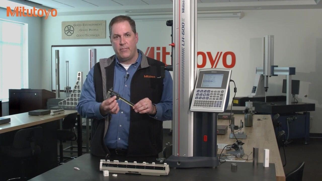
Begin the demonstration with a digital caliper for a brief review of the general calibration method. Precision is not the focus of this portion; the goal is to summarize the sequence of measurements.
For the outside jaws, take a series of measurements across the caliper's measuring range at 1 inch, 2 inches, 4 inches, and 6 inches, varying the position across the jaws for each measurement.
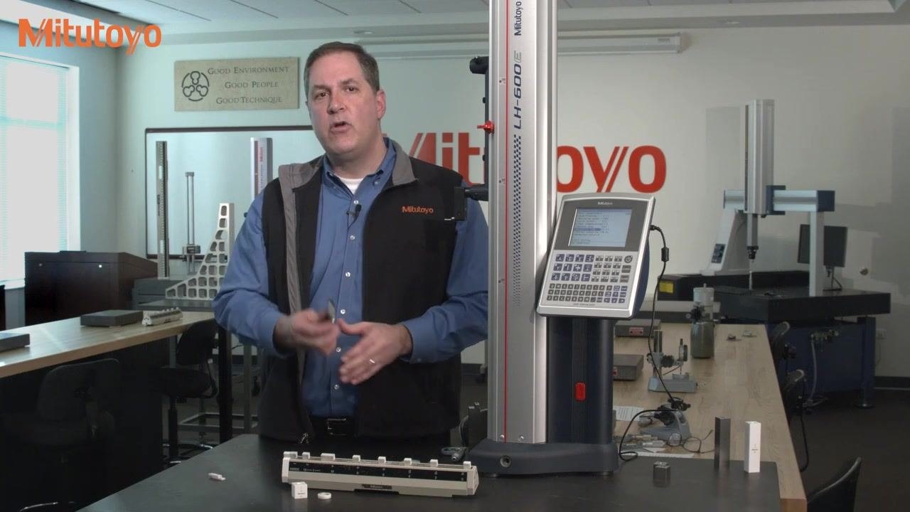
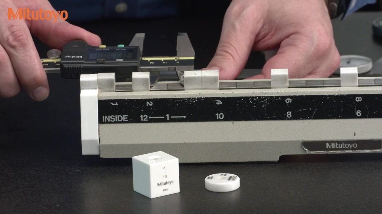
For the inside jaws, perform an inside measurement at 1 inch using the calibration fixture.
For the depth bar, use the depth bar of the caliper to take a measurement on the fixture.
If the caliper has a step function, perform a measurement using the step function as part of the calibration sequence.
Dial caliper calibration and pointer position checks
Before repeating the general sequence with a dial caliper, measure a 0.200-inch (200 thousandths) ring gauge using the inside jaws to confirm there are no issues with the small inside knife edges of the caliper.
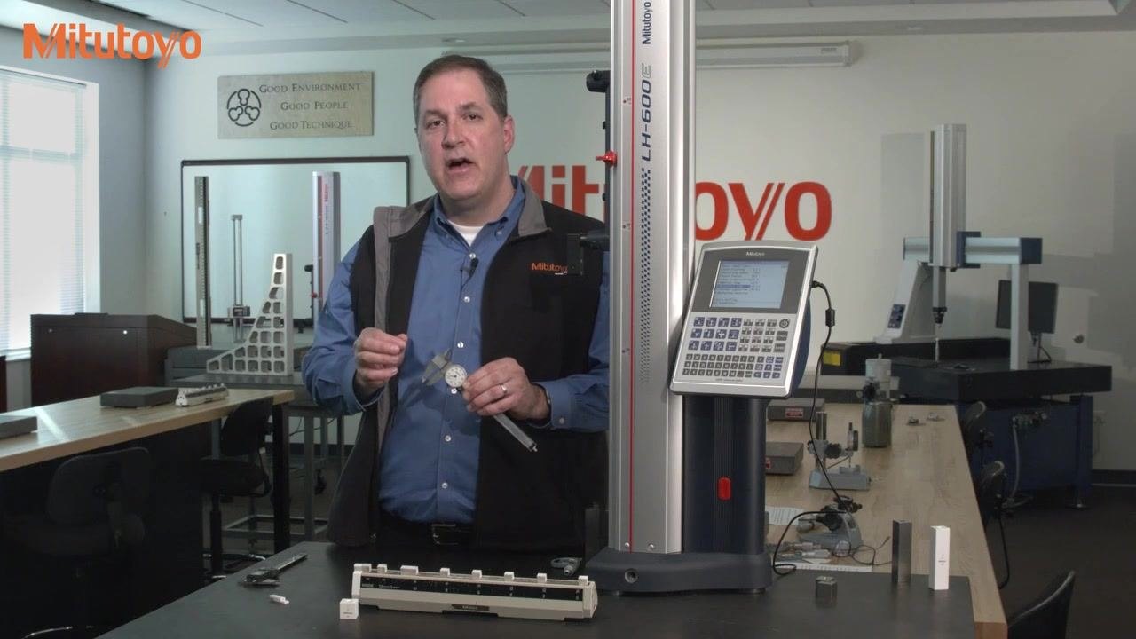
Prepare the dial caliper for the same sequence of measurements, paying close attention to the angular position of the pointer on the dial throughout.
Measure at 1 inch using the outside jaws and observe that the pointer sits at the 12 o'clock position.
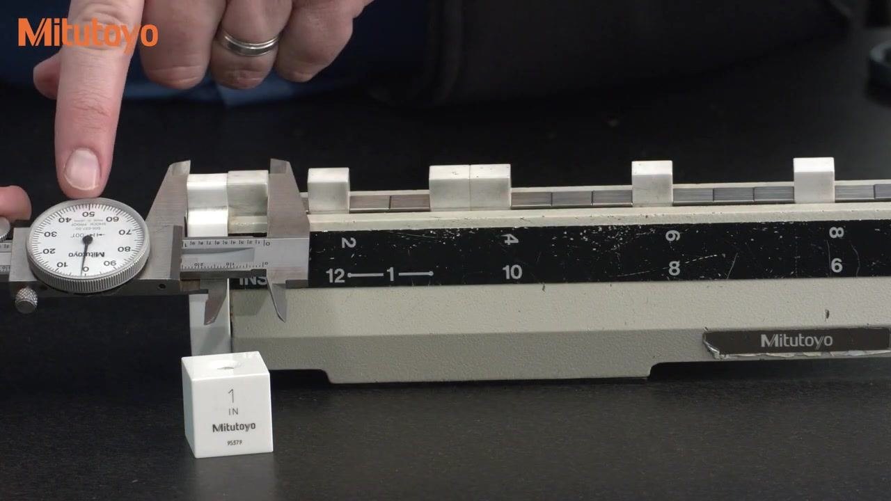
Continue the outside measurements at 2 inches, 4 inches, and 6 inches, confirming for each that the pointer remains at 12 o'clock.
Perform the inside, depth, and step measurements with the dial caliper and observe that the pointer is still at 12 o'clock for each, showing that these standard points alone do not move the pointer to other angular positions.
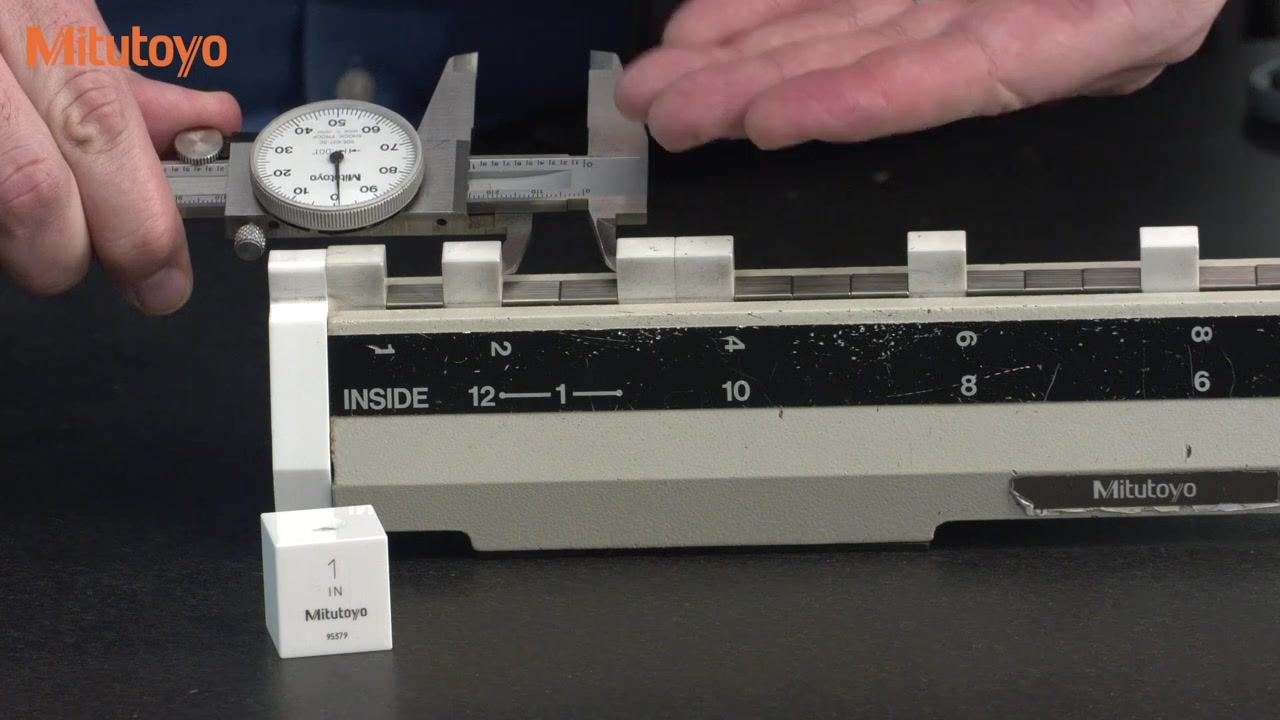
This is a known limitation: dial calipers use internal gears that can wear over time, and errors within a single rotation of the dial go undetected if every calibration point leaves the pointer at the same position. ASME B89.1.14 requires test points that move the pointer to additional angular positions, not just 12 o'clock.
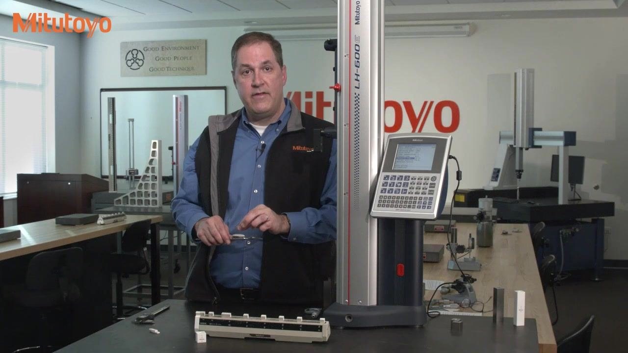
Additional angular test points
Select a 0.125-inch (125 thousandths) gauge block and a 0.150-inch (150 thousandths) gauge block from a standard gauge block set; these are commonly available and can be rung together to create a combined test point.
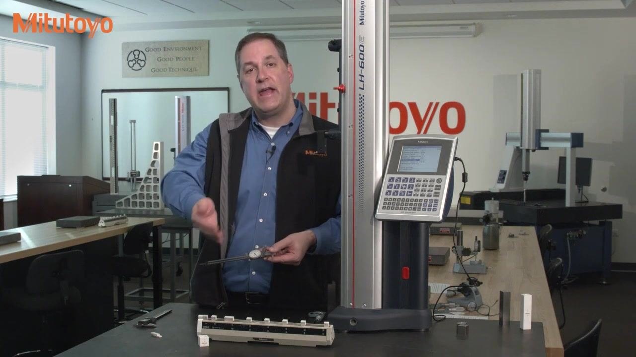
Measure the 0.125-inch gauge block with the outside jaws of the dial caliper; the pointer should read at the 3 o'clock position.
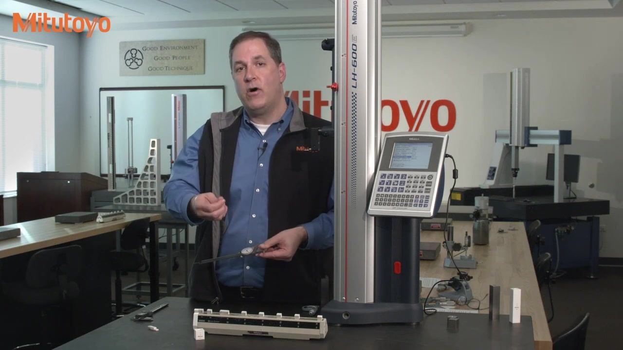
Measure the 0.150-inch gauge block with the outside jaws of the dial caliper; the pointer should read at the 6 o'clock position.
Ring the two blocks together and measure the combined 0.275-inch thickness with the outside jaws; the pointer should read at the 9 o'clock position.
These three measurements (0.125", 0.150", and 0.275" combined) provide three additional, easy-to-implement test points, each moving the pointer to a different angular position to help catch errors the 12 o'clock-only sequence would miss.
ASME B89.1.14 does not prescribe specific test points, so you have flexibility in choosing them—provided the pointer is checked at various angular positions for comprehensive calibration.
Results summary table
| Test Point | Instrument Type | Nominal Value | Pointer Position (Dial) | Measured / Observed Result | Acceptance Criteria | Pass/Fail | Analyst Initials |
|---|---|---|---|---|---|---|---|
| Outside, 1" | Digital | 1.000" | N/A | 1.271 shown (demo, not precision check) | To be recorded | To be recorded | To be recorded |
| Outside, 2", 4", 6" | Digital | 2", 4", 6" | N/A | To be recorded | To be recorded | To be recorded | To be recorded |
| Inside, 1" | Digital | 1.000" | N/A | To be recorded | To be recorded | To be recorded | To be recorded |
| Depth bar | Digital | As shown | N/A | To be recorded | To be recorded | To be recorded | To be recorded |
| Step function | Digital | As shown | N/A | To be recorded | To be recorded | To be recorded | To be recorded |
| Inside, ring gauge | Dial | 0.200" | N/A | Confirms no knife-edge issue | To be recorded | To be recorded | To be recorded |
| Outside, 1", 2", 4", 6" | Dial | 1"–6" | 12 o'clock | To be recorded | To be recorded | To be recorded | To be recorded |
| Inside / depth / step | Dial | As shown | 12 o'clock | To be recorded | To be recorded | To be recorded | To be recorded |
| Outside, gauge block | Dial | 0.125" | 3 o'clock | To be recorded | To be recorded | To be recorded | To be recorded |
| Outside, gauge block | Dial | 0.150" | 6 o'clock | To be recorded | To be recorded | To be recorded | To be recorded |
| Outside, blocks rung together | Dial | 0.275" | 9 o'clock | To be recorded | To be recorded | To be recorded | To be recorded |
Specific pass/fail limits, exact measured readings for each dial test point, and analyst initials were not stated in this session; record them at the time of calibration using your lab's acceptance criteria.
Maintenance
The session notes that dial calipers rely on internal gears that can wear over time, which is why pointer-position checks at multiple angular positions matter. Preventive maintenance actions, parts replaced, and any service provider used were not addressed and should be logged separately per your lab's maintenance procedure.
Out-of-Tolerance Actions
If a dial caliper only reaches the 12 o'clock pointer position across all standard test points, gear wear errors within that rotation may go undetected; testing at 3, 6, and 9 o'clock (using the 0.125", 0.150", and combined 0.275" gauge blocks) helps surface such errors. Formal impact assessment, review of affected data, quarantine procedures, and corrective action steps for an out-of-tolerance finding were not detailed in this session and should follow your lab's standard nonconformance process.
Approval
Reviewer identity, approval date, and the release-to-use decision were not part of this demonstration and should be completed by the responsible quality role after the calibration record is finalized.
What's Next
For further learning on caliper calibration and related metrology topics, refer to the additional training videos suggested at the end of this session.
Generation details: cost, quality tiers, downloads
Docsie billed 3,000 credits ($2.10) to analyze this 6-minute video at standard quality. The rewrite, template fill and Word/PDF exports were included. The same video at each quality tier:
| Quality | Frames sampled | Credits | Approx. cost |
|---|---|---|---|
| Draft | every 16-30 s | 1,500 | $1.05 |
| Standard (this guide) | every 8-15 s | 3,000 | $2.10 |
| Detailed | every 4-7 s | 6,000 | $4.20 |
| Ultra | every 1-3 s | 12,000 | $8.40 |
Credits priced at $0.70 per 1,000; plans include a monthly allowance. Enterprise customers on on-premise or bring-your-own-model deployments run this on their own inference and pay no per-video credits.
Generated by Docsie Video-to-Docs on 2026-09-28 from a 5-minute video. It was generated straight into Docsie's Instrument Calibration Log template, so every section of that template is filled from the video. Screenshots are frames from the source video and belong to their creator, Mitutoyo America Corporation, whose original is embedded above. If you own this video and want the guide removed or credited differently, contact us and we will act within one business day.