
How to Calculate Speeds and Feeds
This procedure explains how to calculate speeds and feeds for any tool and material combination in CNC machining. It walks through the formula used to determine the correct spindle speed (RPM) for your CNC program, along with the calculation used to establish the correct feed rate. All values and examples in this procedure use metric units; a separate reference is available if you require inch-based values.
Video: How To Calculate Speeds and Feeds (Metric Version) - Haas Automation Tip of the Day by Haas Automation, Inc. (2018). All credit for the demonstration goes to the creator; watch the original on YouTube. The written guide below was generated from this video by Docsie. Creator? Request a change or removal.
This procedure explains how to calculate speeds and feeds for any tool and material combination in CNC machining. It walks through the formula used to determine the correct spindle speed (RPM) for your CNC program, along with the calculation used to establish the correct feed rate. All values and examples in this procedure use metric units; a separate reference is available if you require inch-based values.
Purpose
This procedure provides a repeatable method for calculating reliable starting spindle speed (RPM) and feed rate (F-code) values before running a CNC program, so that tools are neither underused nor damaged by excessive cutting speeds.
Scope
This procedure applies to any CNC milling job where you need to determine the S-code (spindle speed) and F-code (feed rate) for a given tool and workpiece material. All calculations shown use metric units (mm, m/min, RPM).
Required reference materials
Before you begin, gather the following:
- The job setup sheet, since all calculations and planning begin here.
- The tool manufacturer's catalog or manual, ideally in digital (PDF) form.
- The exact tool being used, including its diameter and number of teeth/flutes, and whether it has a coating (coatings can double allowable cutting speeds).
- A calculator, or a digital speeds-and-feeds app, or access to your CNC control's built-in milling calculator.
Understanding surface speed
-
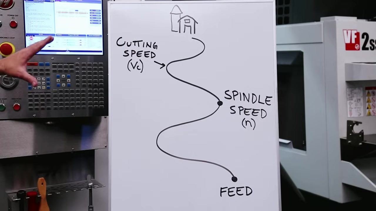
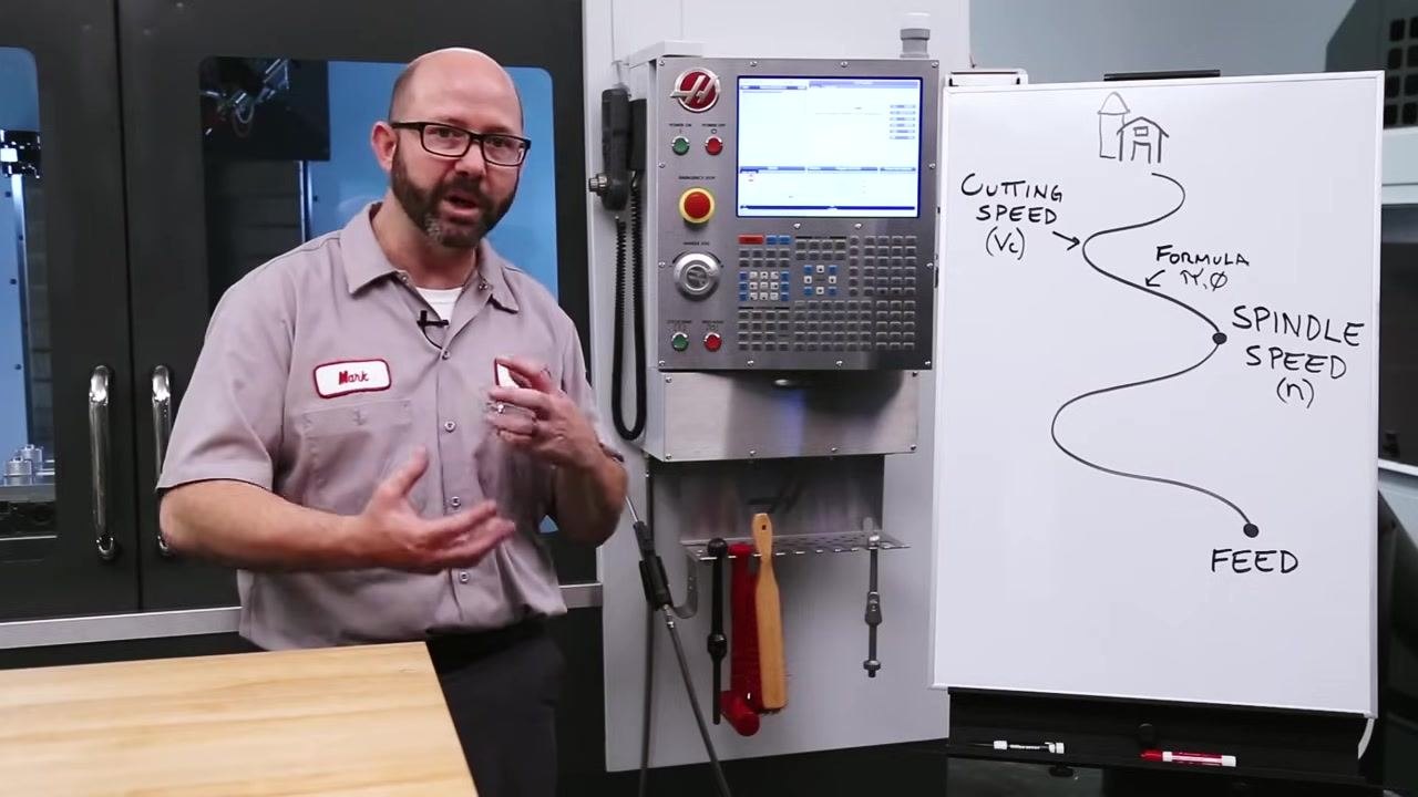
Review the overall path from setup to speed and feed values. All calculations begin with your setup sheet and lead first to determining spindle speed, then feed rate.
-
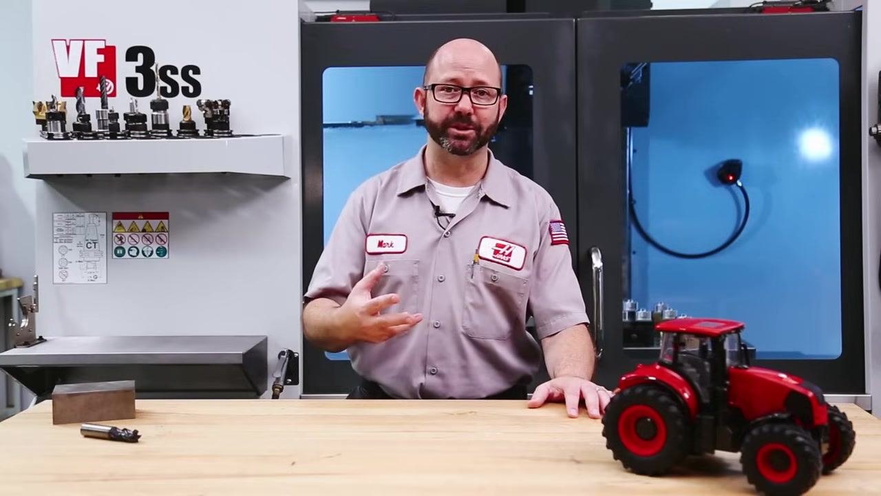
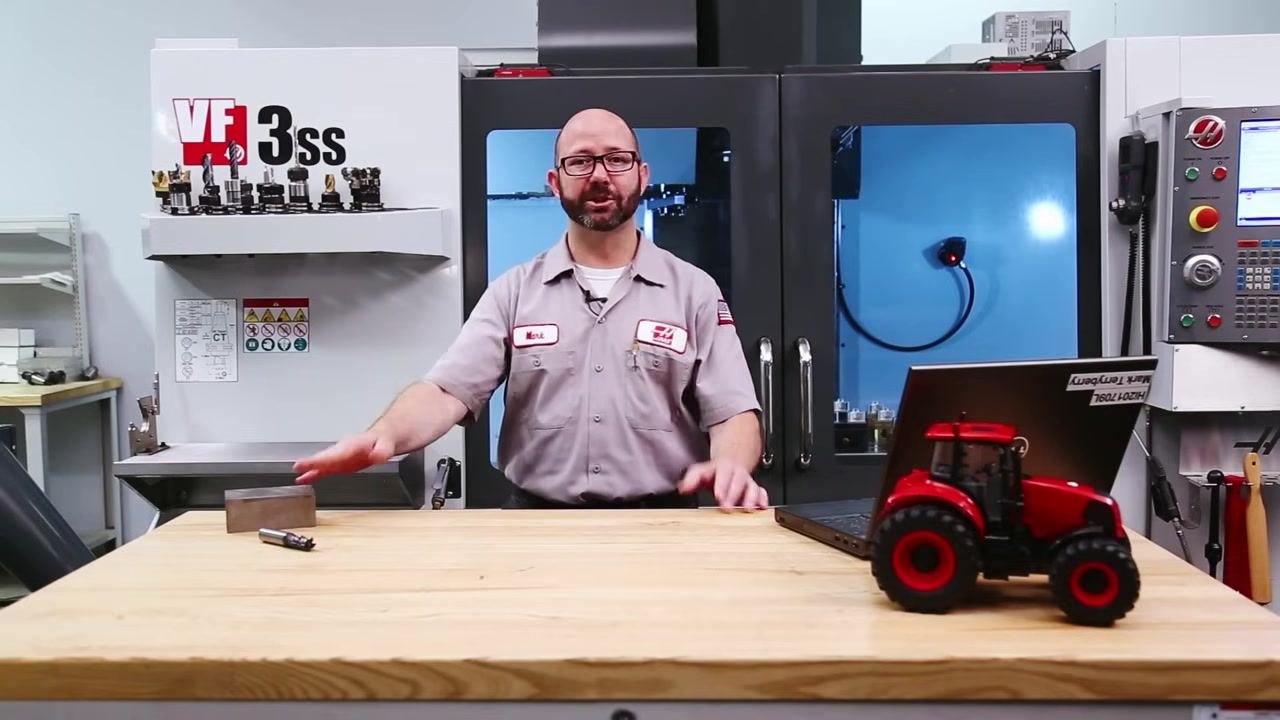
Consider the surface speed analogy. If a tractor moves at 1 kilometer per hour (about 17 meters per minute), both the small front tire and the large rear tire travel at the same surface speed where the rubber meets the road, even though the tires are different sizes.
-
Confirm the result of the analogy. Both tires travel at 17 surface meters per minute. This shows that surface speed is independent of the diameter of the rotating object, which applies directly to tool surface speed in machining.
-
Remember the key takeaway: surface speed (meters per minute) stays the same at the contact point, regardless of the diameter of the tire or tool.
Calculating circumference and identifying maximum cutting speed
- Recognize that RPM differs even though surface speed is the same. The smaller tire (or tool) must rotate more times per minute than the larger one to cover the same ground. In the tractor example, the small front tire turns at 54 RPM while the large rear tire turns at 42 RPM to cover the same distance.

-
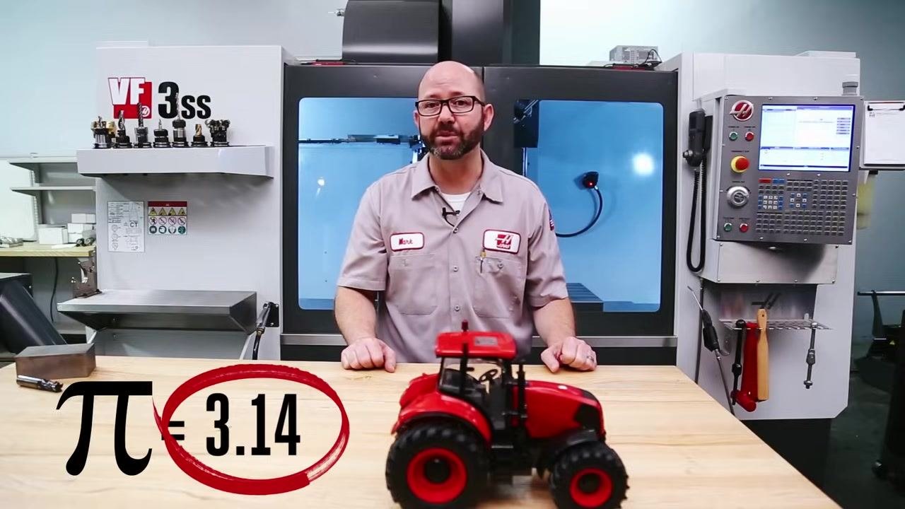
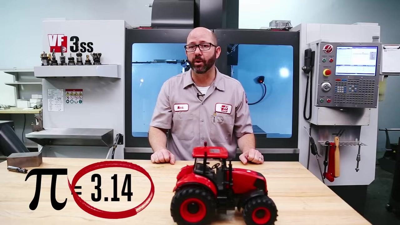
Calculate circumference using diameter × π. Pi (π) is the constant ratio between a circle's diameter and its circumference, approximately 3.14.
-
Work through the example calculations:
- For a 100 mm diameter tire: Circumference = 100 mm × 3.14 = 314 mm.
- For a 1 meter diameter tire: Circumference = 1 m × 3.14 = 3.14 m.
-
Note the safety and tooling limit implied by this concept. Just as a tire can overheat and fail if spun too fast, a cutting tool has a maximum surface speed for each material. Exceeding it causes overheating and rapid tool wear. Always check the recommended maximum cutting speed for your specific tool and material combination.
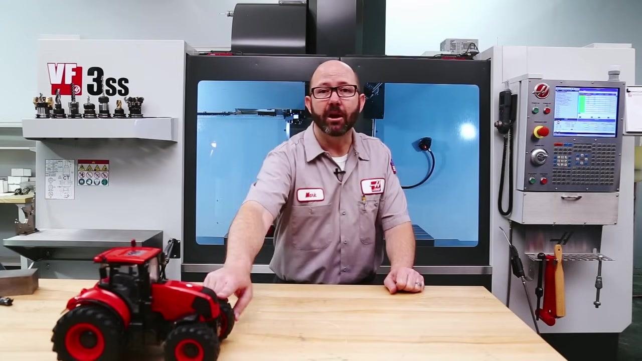
- Summarize the two rules to carry forward:
- Use Circumference = Diameter × π (3.14) to find how much material is covered per revolution.
- Never exceed the maximum recommended cutting speed for your tool and material, to avoid premature tool failure.
Converting cutting speed to spindle speed (RPM)
- Distinguish between the two key speeds in machining. Cutting speed (Vc) is the surface speed where the tool meets the part, measured in meters per minute (m/min). Spindle speed (n) is the number of revolutions per minute the spindle turns — the value your CNC control needs, entered as the S-code.
-
Confirm the units for each variable:
- Cutting speed (Vc): meters per minute (m/min)
- Spindle speed (n): revolutions per minute (RPM)
- Tool diameter (D): millimeters (mm)
- Pi (π): 3.14
-
Locate where RPM and feed values are entered in your G-code. Spindle speed is set with the S-code (for example, S1500 for 1500 RPM), and feed rate is set with the F-code (for example, F1000 for 1000 mm/min). Calculate both values before running the program.
-
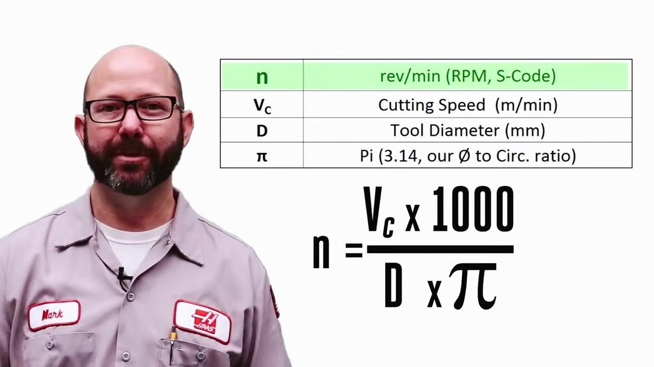
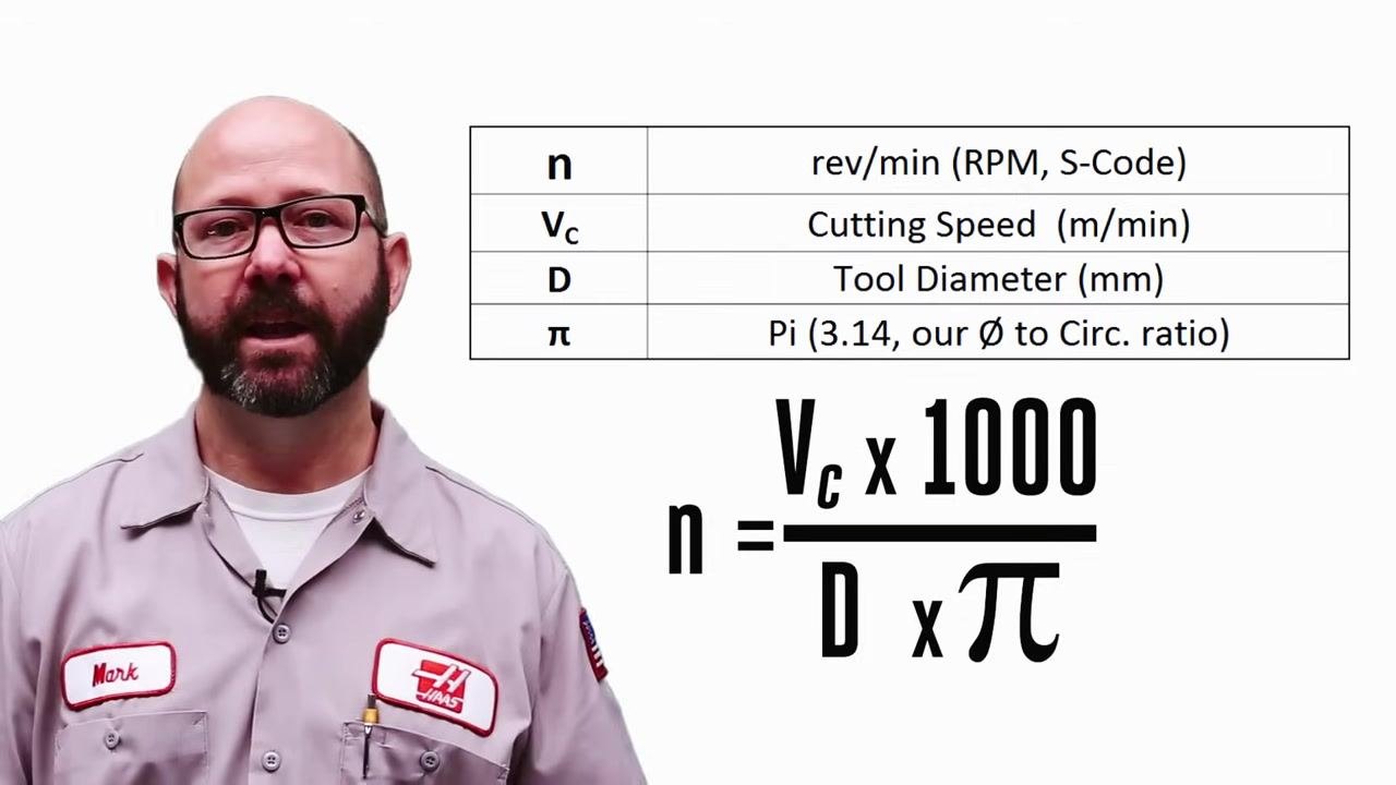
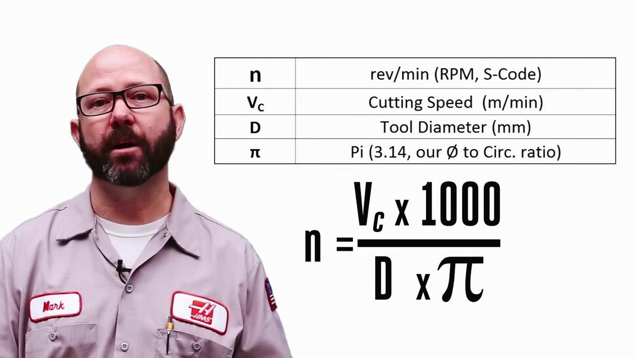
Apply the spindle speed formula:
n = (Vc × 1000) / (D × π)- n = spindle speed (RPM, S-code)
- Vc = cutting speed (m/min)
- D = tool diameter (mm)
- π = 3.14
This formula converts the surface speed from the tool catalog and the tool diameter into the RPM value your CNC machine needs.
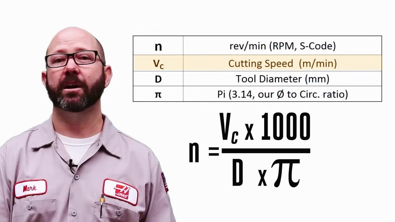
- Reference the standard symbols used by tool suppliers:
| Symbol | Meaning |
|---|---|
| n | rev/min (RPM, S-Code) |
| Vc | Cutting Speed (m/min) |
| D | Tool Diameter (mm) |
| π | Pi (3.14, diameter-to-circumference ratio) |
-
Pay particular attention to Vc and D, since these are the two values you will need to obtain from the catalog or measure directly before you can calculate spindle speed.
-
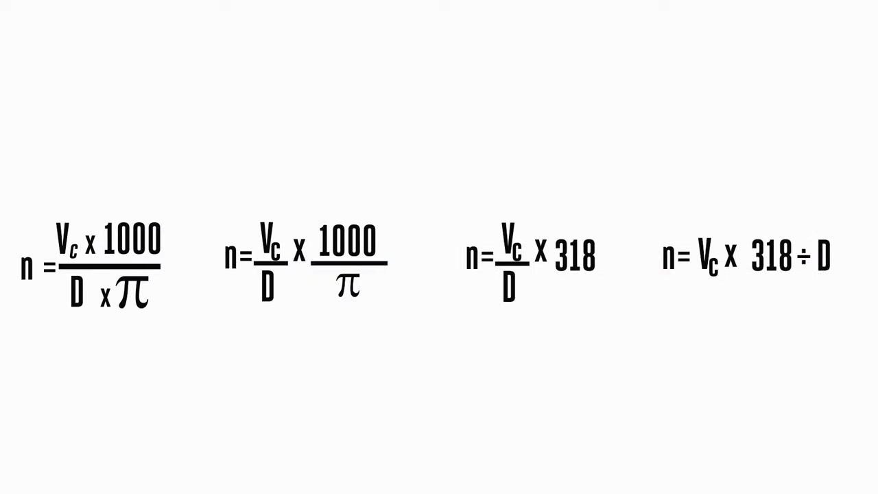
Simplify the formula for faster calculation. Dividing 1000 by π gives approximately 318, allowing the formula to be simplified as follows:
n = (Vc × 1000) / (D × π)
   n = (Vc / D) × (1000 / π)
   n = (Vc / D) × 318
   n = Vc × 318 ÷ D
Selecting the correct cutting speed from the tool catalog
- Confirm the workpiece material before opening the catalog. In this example, the workpiece is labeled STEEL 4140, and the cutting tool is marked SD99-200.
Caution: Modern cutting tools may have coatings that can double their allowable cutting speeds. Know the exact tool you are using so that you don't rely on outdated or overly conservative speed values.
-
Access the tool manufacturer's catalog, downloading the manual or catalog in PDF form when possible.
-
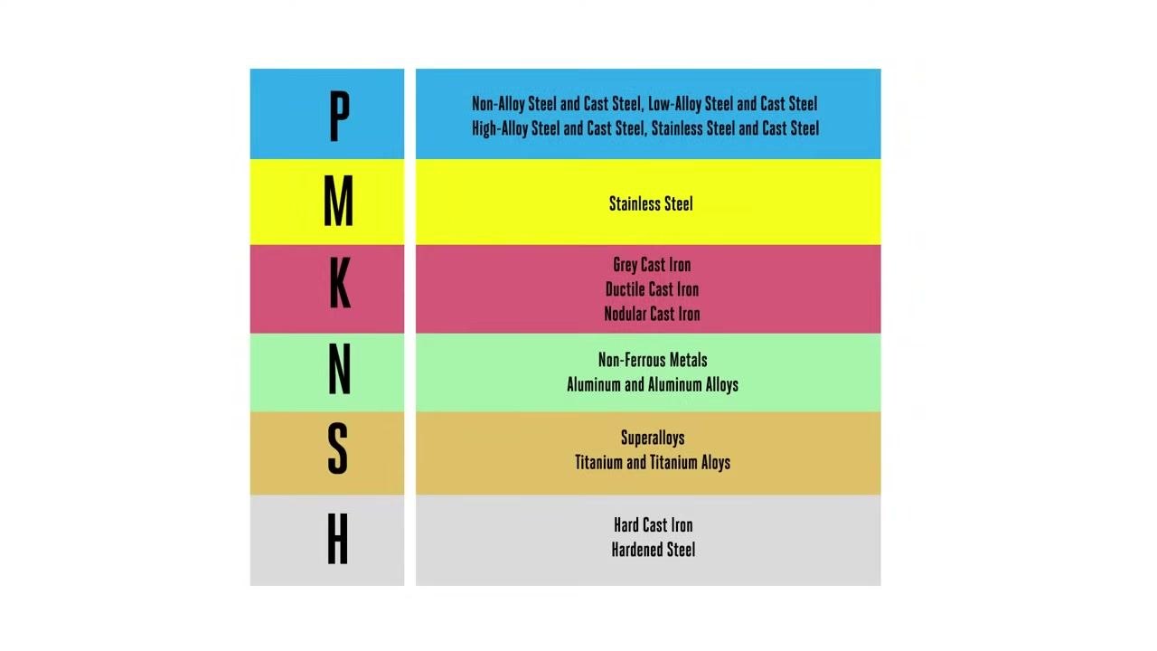
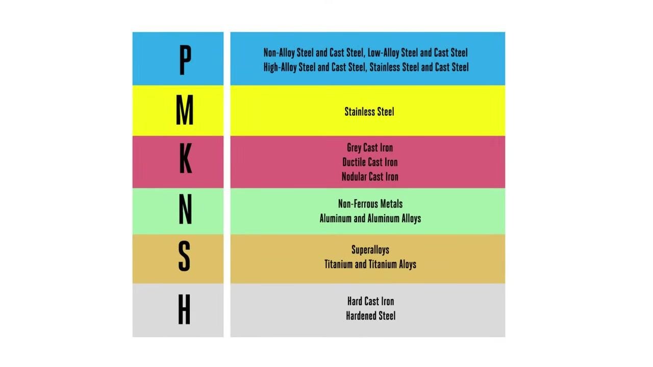
Use the color-coded material chart to quickly identify your material group:
- P (Blue): Non-Alloy Steel and Cast Steel, Low-Alloy Steel and Cast Steel, High-Alloy Steel and Cast Steel, Stainless Steel and Cast Steel
- M (Yellow): Stainless Steel
- K (Red): Grey Cast Iron, Ductile Cast Iron, Nodular Cast Iron
- N (Green): Non-Ferrous Metals, Aluminum and Aluminum Alloys
- S (Brown): Superalloys, Titanium and Titanium Alloys
- H (Gray): Hard Cast Iron, Hardened Steel
Matching your material to the ISO group and catalog code
- Identify your material group on the chart. The ISO groups are: N (Green) Non-Ferrous Metals/Aluminum Alloys, S (Brown) Superalloys/Titanium Alloys, K (Red) Cast Irons, M (Yellow) Stainless Steel, P (Blue) Steels, and H (Gray) Hardened Materials.
-
Confirm your specific workpiece material. In this example, the material is 4140 steel, a common alloy steel used in machining.
-
Be aware that material names vary by country. 4140 is a U.S. designation for this material; other regions may use a different name for the same alloy.
-
Match your material to the ISO group regardless of local naming. Worldwide, 4140 steel falls under the P (blue) ISO material group for steels. Reference the full chart for all groups and descriptions.
-
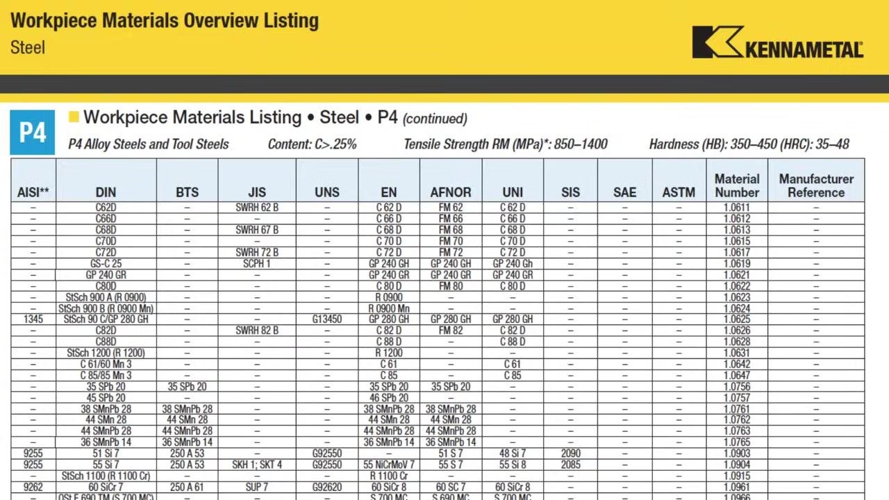
Look up your material in the manufacturer's catalog. For Kennametal, 4140 steel is listed as P4 (P4 Alloy Steels and Tool Steels). The catalog cross-references international standards (AISI, DIN, JIS, etc.), tensile strength, and hardness.
-
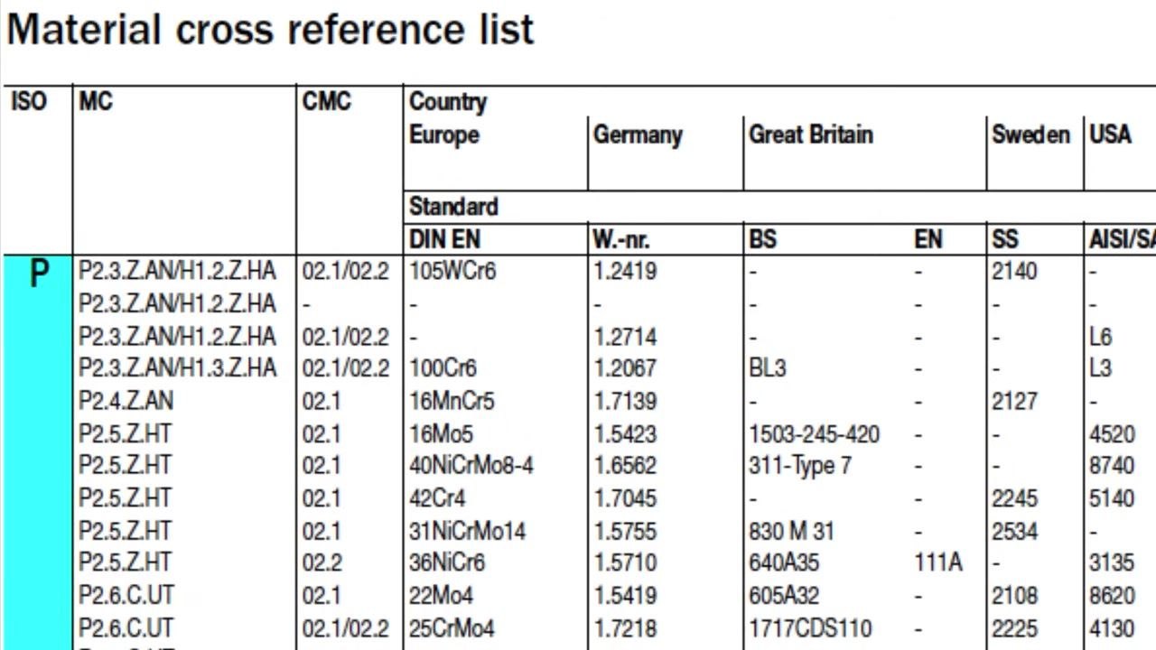
Note that the code following the ISO letter varies by manufacturer. For the same material, Sandvik uses P2.1, and Iscar/Widia use P6 or P7. Use the material cross-reference list to match your material to the correct code in each catalog.
Caution: Choosing the wrong material group or code can lead to improper speeds and feeds, causing rapid tool wear or failure.
-
Never apply cutting speeds for one material group to another. For example, running a drill or end mill in titanium at speeds meant for mild steel will damage the tool.
-
Contact your tooling representative if you are unsure which material group or catalog code applies to your job.
Calculating spindle speed (RPM) for your job
- Locate the recommended cutting speed for your material group and code in the cutting speed chart. Values are listed in meters per minute (Vc). Example values from an ISO 513 chart:
- P1: 150 m/min
- P2: 130 m/min
- P3: 115 m/min
- P4: 105 m/min
- P5: 100 m/min
- P6: 50 m/min
-
Select the appropriate cutting speed for your setup, taking into account tool length, setup rigidity, and how aggressively you plan to cut. A more rigid setup allows for higher cutting speeds; a less rigid setup calls for a lower cutting speed to avoid tool chatter or breakage.
-
Record your chosen cutting speed. For this example, 100 m/min is selected for the P5 group, 4140 steel job.
-
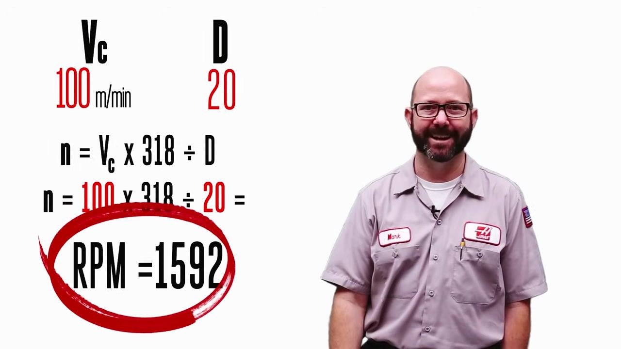
Apply the simplified spindle speed formula:
n = Vc × 318 ÷ D- n = spindle speed (RPM)
- Vc = cutting speed (m/min)
- D = tool diameter (mm)
-
Substitute your values into the formula. For this example, using a 20 mm end mill:
- Vc = 100 m/min
- D = 20 mm
- n = 100 × 318 ÷ 20
-
Calculate the result. n = 100 × 318 ÷ 20 = 1592 RPM.
-
Confirm the outcome: you now know how fast to spin your tool — your spindle speed is 1592 RPM.
Calculating feed rate for end mills
-
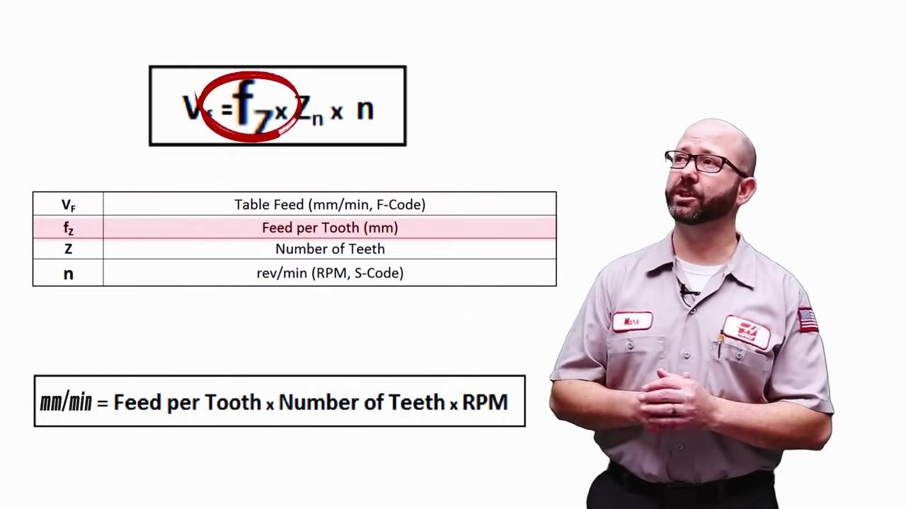
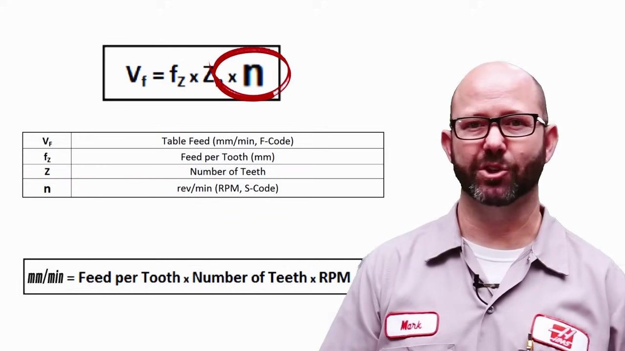
Apply the feed rate formula for end mills:
Vf = fz × Zn × n- Vf = Table Feed (mm/min, F-Code)
- fz = Feed per Tooth (mm)
- Zn = Number of Teeth
- n = Revolutions per minute (RPM, S-Code)
-
Read the formula in plain terms: table feed (mm/min) equals feed per tooth times the number of teeth times RPM.
-
Confirm what "n" represents in the formula — revolutions per minute (RPM, S-Code), the spindle speed you already calculated.
-
Count the number of teeth on your tool. Different end mills have different tooth counts — for example, one tool may have six teeth and another four. This number (Zn) is required for the formula.
-
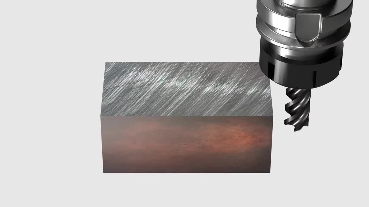
Understand why feed per tooth matters: the goal is for each tooth to take a specific, controlled "bite" of material with every pass.
-
Reference the manufacturer's cutting feed chart for recommended starting values of feed per tooth (fz) and number of teeth (Zn) by tool diameter. Example values:
- SD99-030: D = 3.0 mm, Zn = 4, Roughing fz = 0.020 mm, Finishing fz = 0.013 mm
- SD99-120: D = 12.0 mm, Zn = 4, Roughing fz = 0.085 mm, Finishing fz = 0.055 mm
-
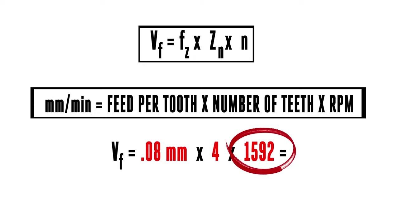
Substitute your values into the formula. Using fz = 0.08 mm, Zn = 4, and n = 1592 RPM:
Vf = 0.08 mm × 4 × 1592 -
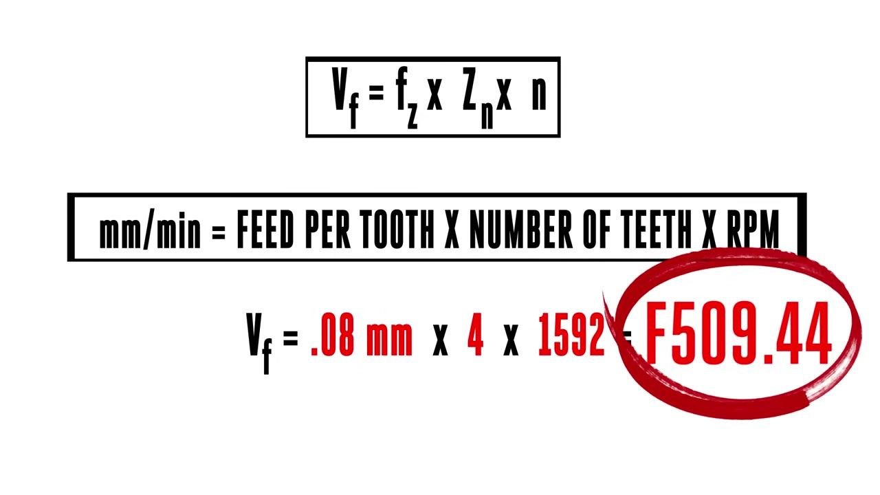
Calculate the final feed rate. Vf = 0.08 × 4 × 1592 = 509.44, giving a feed rate of F509.44. This represents how far the centerline of the tool moves along its programmed path, in mm per minute.
-
Note that manufacturer recommendations vary. Some manuals provide a single feed rate for all cutting conditions, but most provide separate values depending on the operation — always consult the specific manufacturer data for your tool.
Adjusting feed rate for slotting, side milling, and feed per revolution
-
Recognize that manufacturers typically provide at least two feed rate recommendations for end mills: one for slotting operations and one for side milling operations.
-
Reference the manufacturer's application data chart for specific values. A typical chart (for example, Kennametal's "General Purpose Solid Carbide End Mills – GOmill GP") provides:
- Tool type and specifications (e.g., 4 flute, short, regular)
- Material group codes
- Cutting speed ranges (SFM)
- Feed per tooth (IPT) by tool diameter
- Separate columns for side milling (A) and slotting (B)
- A note that, for slotting (B), IPT should be reduced by 20% compared to side milling (A)
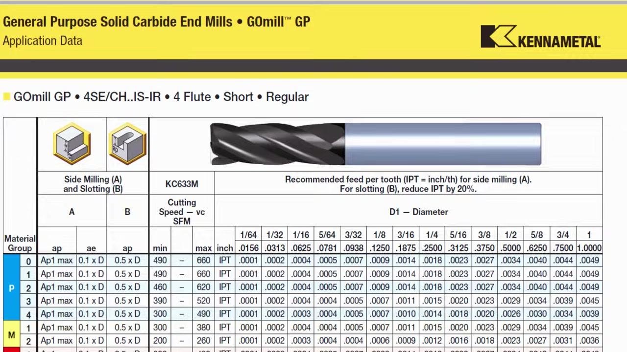
- Reduce feed per tooth when slotting. When slotting, the feed per tooth ("bite") should typically be about 25% less than when side milling.
Caution: Always follow the manufacturer's speed and feed recommendations rather than estimating, to achieve optimal results and tool life.
-
Recognize when a chart provides feed per revolution instead of feed per tooth. This is common for tools like drills.
-
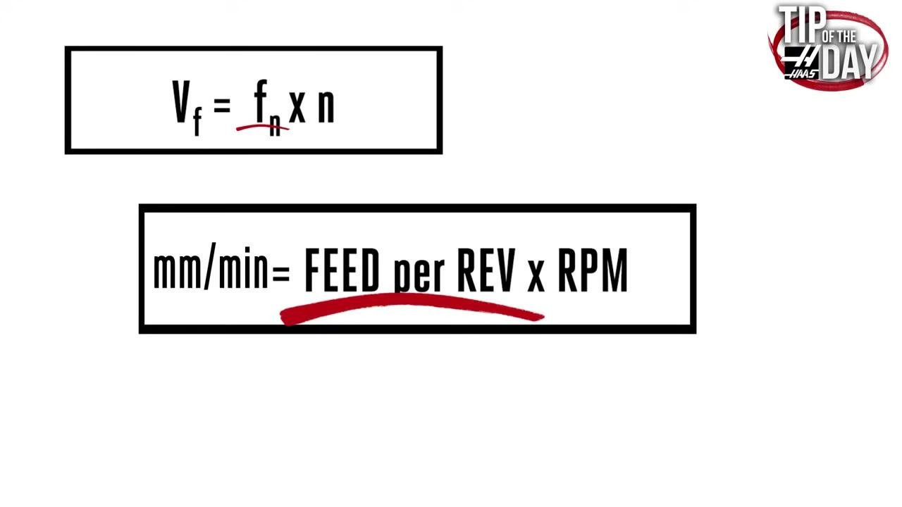
Apply the feed-per-revolution formula:
Vf = fn × n- Vf = Table Feed (mm/min)
- fn = Feed per Revolution (mm)
- n = RPM
-
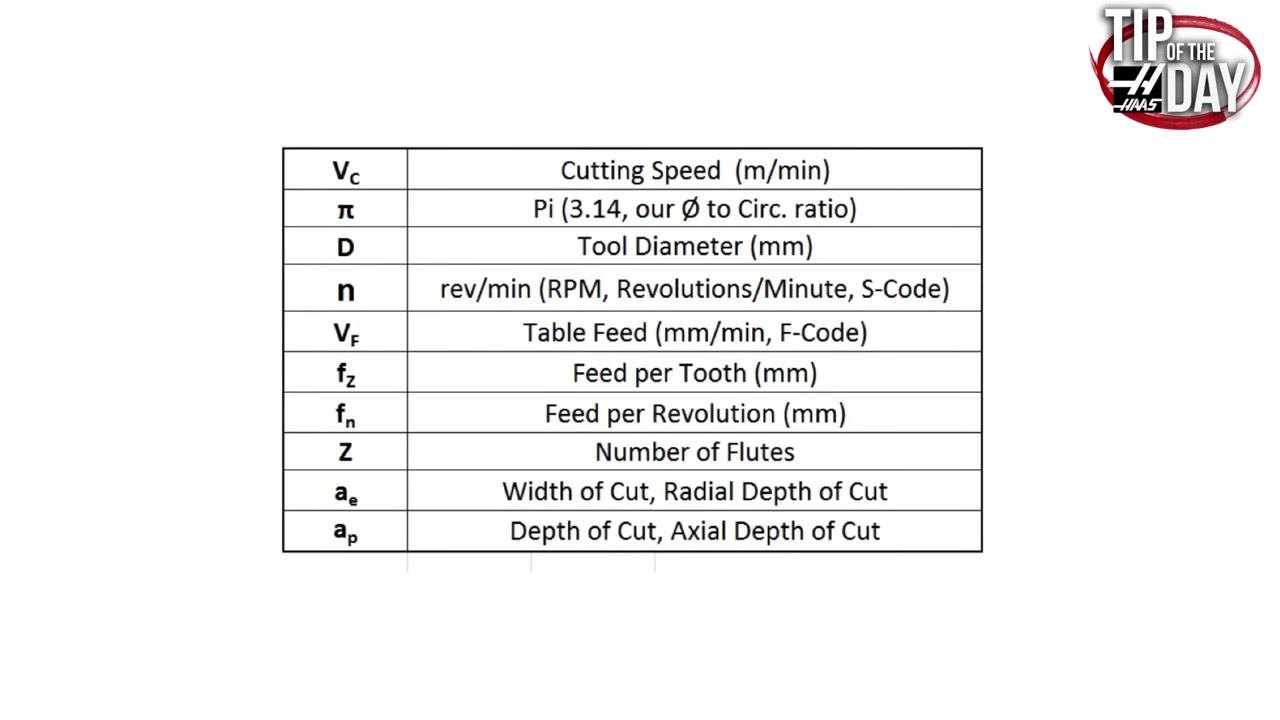
Review the complete legend of variables used across all speed and feed calculations:
| Symbol | Meaning |
|---|---|
| Vc | Cutting Speed (m/min) |
| π | Pi (3.14, diameter-to-circumference ratio) |
| D | Tool Diameter (mm) |
| n | rev/min (RPM, S-Code) |
| VF | Table Feed (mm/min, F-Code) |
| fz | Feed per Tooth (mm) |
| fn | Feed per Revolution (mm) |
| Z | Number of Flutes |
| ae | Width of Cut, Radial Depth of Cut |
| ap | Depth of Cut, Axial Depth of Cut |
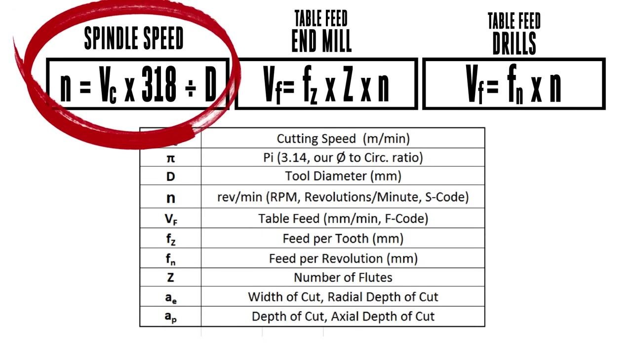
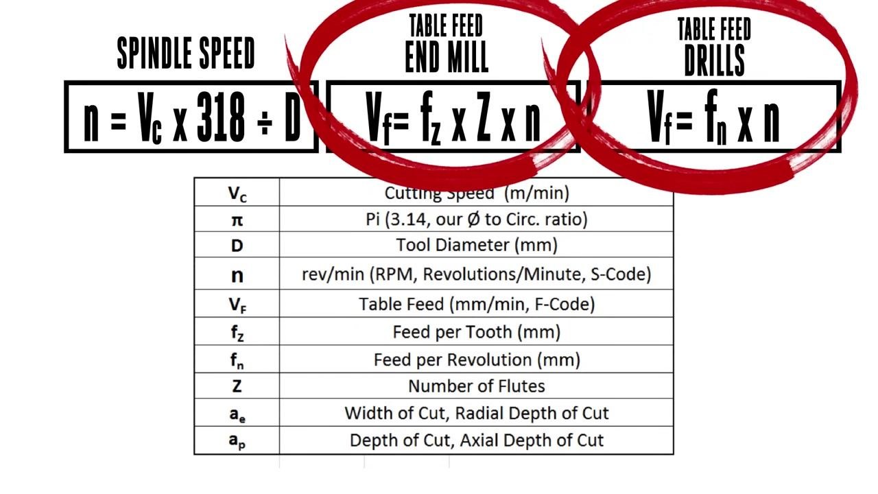
- Keep the three key formulas together for quick reference:
- Spindle Speed: n = Vc × 318 ÷ D
- Table Feed (End Mill): Vf = fz × Z × n
- Table Feed (Drills): Vf = fn × n
Using catalogs and digital tools instead of manual calculation
- Review the same three core formulas for spindle speed and table feed before moving to catalog- or software-based methods.
-
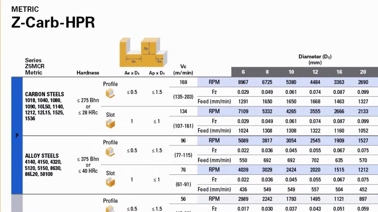
Check whether your tooling catalog already provides RPM and feed rate directly. Many catalogs eliminate manual calculation entirely. For example, a "Z-Carb-HPR" series chart for carbon and alloy steels lists material type, hardness, operation type (profile or slot), cutting speed (Vc), tool diameter (6–20 mm), RPM, feed per tooth (Fz), and feed rate (mm/min) for each diameter.
-
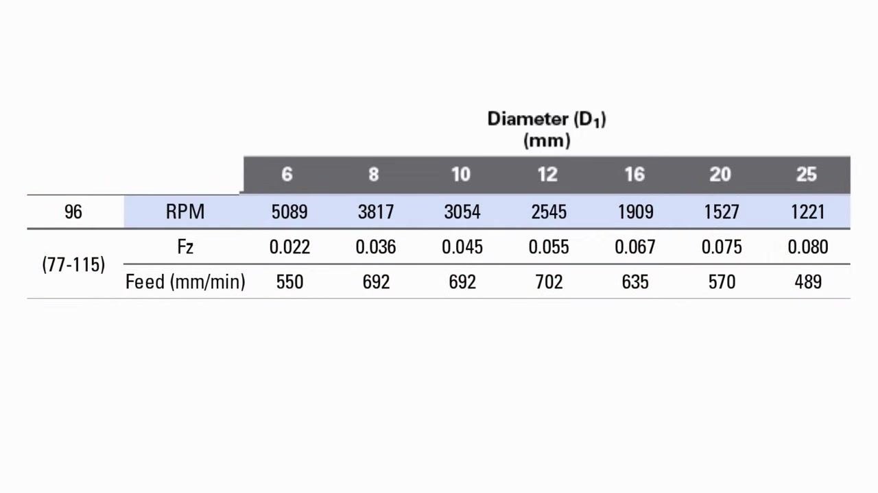
Use the table values directly when provided, without applying the formulas. For example, for a 12 mm tool in alloy steel at a 96 m/min cutting speed:
- RPM = 2545
- Feed per tooth (Fz) = 0.055 mm
- Feed rate = 702 mm/min
-
Consider using a digital speeds-and-feeds tool. Smartphone apps or PC software can calculate feed rates and speeds quickly and accurately as an alternative to manual formulas.
- On machines with next-generation controls, use the built-in milling calculator by pressing the Current Commands button.
- Consult additional resources for tapping feed rate calculations, since tapping uses its own set of considerations not covered by the end mill and drill formulas above.
Verification and summary
Before running your CNC program, confirm the following:
- You have identified the correct ISO material group and manufacturer catalog code for your workpiece material.
- You have selected a cutting speed (Vc) appropriate to your material, tool coating, and setup rigidity.
- You have calculated spindle speed using n = Vc × 318 ÷ D and entered it as the S-code.
- You have calculated feed rate using Vf = fz × Zn × n (end mills) or Vf = fn × n (feed per revolution) and entered it as the F-code, adjusting fz downward for slotting versus side milling as recommended.
- Where available, you have cross-checked your calculated values against direct RPM and feed rate tables in the tooling catalog.
What's next
With spindle speed (S-code) and feed rate (F-code) calculated and entered into your program, you are ready to proceed with running the CNC job. For tapping operations specifically, consult additional resources on tapping feed rate calculations, as tapping requires separate considerations beyond the end mill and drill formulas covered in this procedure.
Generation details: cost, quality tiers
Docsie billed 7,500 credits ($5.25) to analyze this 15-minute video at standard quality. The rewrite, template fill and Word/PDF exports were included. The same video at each quality tier:
| Quality | Frames sampled | Credits | Approx. cost |
|---|---|---|---|
| Draft | every 16-30 s | 3,750 | $2.62 |
| Standard (this guide) | every 8-15 s | 7,500 | $5.25 |
| Detailed | every 4-7 s | 15,000 | $10.50 |
| Ultra | every 1-3 s | 30,000 | $21.00 |
Credits priced at $0.70 per 1,000; plans include a monthly allowance. Enterprise customers on on-premise or bring-your-own-model deployments run this on their own inference and pay no per-video credits.
Generated by Docsie Video-to-Docs on 2026-09-20 from a 14-minute video. Screenshots are frames from the source video and belong to their creator, Haas Automation, Inc., whose original is embedded above. If you own this video and want the guide removed or credited differently, contact us and we will act within one business day.