
How to Read Hvac Gauges
This procedure explains how to read HVAC gauges to check and interpret superheat and subcooling values on an air conditioning system. Using a Fieldpiece digital manifold gauge set, you will connect the equipment, capture readings, and compare them against manufacturer specifications to confirm system performance. The procedure also covers manual calculation methods for situations where a digital gauge is unavailable.
Video: HVAC 065 example Superheat and Subcooling with digital gauges by Love2HVAC with Ty Branaman (2021). All credit for the demonstration goes to the creator; watch the original on YouTube. The written guide below was generated from this video by Docsie. Creator? Request a change or removal.
This procedure explains how to read HVAC gauges to check and interpret superheat and subcooling values on an air conditioning system. Using a Fieldpiece digital manifold gauge set, you will connect the equipment, capture readings, and compare them against manufacturer specifications to confirm system performance. The procedure also covers manual calculation methods for situations where a digital gauge is unavailable.
Purpose
This SOP standardizes the process for checking superheat and subcooling on refrigerant systems. Following these steps helps you confirm correct refrigerant charge, identify airflow restrictions, and determine whether corrective action is required.
Scope
This procedure applies to technicians servicing air conditioning systems that use 410A refrigerant and a Thermostatic Expansion Valve (TXV). It covers gauge connection, reading interpretation, comparison to manufacturer targets, and manual calculation as a backup method.
Required equipment
- Fieldpiece digital manifold gauge set (yellow gauge body)
- Blue hose (for low/suction side connection)
- Red hose (for high/liquid side connection)
- Temperature clamps (two, for suction and liquid lines)
- Manufacturer’s specification tag or documentation for the unit under service
Procedure
Step 1: Connect the digital manifold gauge set
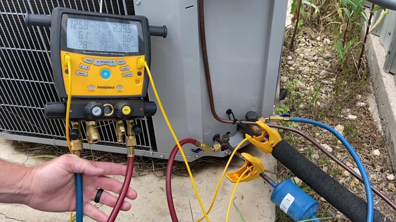
Attach the yellow Fieldpiece digital manifold gauge to the system before taking any readings.
- Connect the blue hose to the low (suction) side service port.
- Connect the red hose to the high (liquid) side service port.
- Attach one temperature clamp to the suction line to capture the low side temperature.
- Attach the second temperature clamp to the liquid line to capture the high side temperature.
- Confirm all hoses and clamps are securely connected before proceeding.
Step 2: Verify gauge readings and setup
Before interpreting any values, confirm the gauge is configured correctly.
- Confirm the gauge is set to the correct refrigerant type: 410A.
- Observe the display for suction pressure (left side, typically in psi) and liquid pressure (right side, typically in psi).
- Note the superheat (SH) and subcooling (SC) values shown on the display.
- Note the suction saturated temperature (SAT) and the liquid saturated temperature (SAT).
- Note the actual suction line and liquid line temperatures.
Step 3: Interpret the low side (suction) readings
Check the suction line temperature against the suction saturated temperature to understand superheat.
- Example: suction saturated temperature is 42°F, representing the point where refrigerant is boiling inside the evaporator.
- Example: suction line temperature is 48.9°F.
- Example: superheat is 6.8°F, automatically calculated by the gauge.
- Superheat is the difference between the suction line temperature and the suction saturated temperature.
Step 4: Interpret the high side (liquid) readings
Check the liquid line temperature against the liquid saturated temperature to understand subcooling.
- Example: liquid saturated temperature is 80.7°F, representing the point where refrigerant is condensing in the condenser.
- Example: liquid line temperature is 71°F.
- Example: subcooling is 9.6°F, automatically calculated by the gauge.
- Subcooling is the difference between the liquid saturated temperature and the actual liquid line temperature.
Step 5: Focus on key values
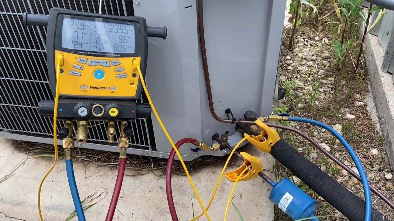
Superheat and subcooling are the two most important values to monitor throughout this procedure.
- Example superheat (SH): 6.8°F
- Example subcooling (SC): 9.6°F
Step 6: Compare to manufacturer specifications
Reference the unit’s data tag to determine the target subcooling value for the system.
- Example: the tag specifies "Indoor TXV subcooling at 8°F."
- Compare the measured subcooling (e.g., 9.7°F) against the target (8°F).
- If subcooling is higher than the target, the system may be slightly overcharged.
Step 7: Diagnose system performance
Use the relationship between superheat and subcooling to identify the underlying issue.
- Low superheat combined with high subcooling can indicate overcharging or airflow issues.
- In the example used in this procedure, low superheat was caused by a dirty air filter restricting airflow inside the system.
Step 8: Take corrective action if needed
Address the root cause identified in the diagnosis before making further adjustments.
- If subcooling is above the target, consider removing refrigerant to reach the specified value.
- If superheat is low due to airflow issues, check and replace or clean the air filter before making refrigerant adjustments.
Step 9: Identify and address airflow issues
A dirty air filter can restrict airflow and prevent the TXV from operating correctly.
- Safety/performance note: The TXV requires sufficient heat (airflow) across the evaporator coil to function as designed. If airflow is insufficient, the TXV will still attempt to maintain superheat, but overall system performance will be compromised.
- Example: the system in this procedure was maintaining superheat above 5°F, but airflow was inadequate due to a dirty filter.
- Locate and replace the dirty air filter to restore proper airflow.
- Ensure the new filter is correctly installed and matches the system’s specifications.
- Only proceed with further diagnostics or adjustments after confirming proper airflow.
Step 10: Observe superheat and subcooling after restoring airflow
With the digital manifold gauge still connected, observe the live readings as airflow is restored.
- Example values after the filter change: superheat (SH) 8.5°F, subcooling (SC) 9.7°F.
- Note: These values may fluctuate as airflow is restored and the system stabilizes.

Step 11: Manually calculate superheat (if no digital gauge is available)
If a digital gauge is not available, calculate superheat using the following formula:
- Superheat = Actual Suction Line Temperature − Suction Saturated Temperature
- Example: 48.9°F (suction line) − 42°F (suction saturated) = 6.9°F superheat.
Step 12: Manually calculate subcooling (if no digital gauge is available)
Calculate subcooling using the following formula when a digital gauge is unavailable:
- Subcooling = Liquid Saturated Temperature − Actual Liquid Line Temperature
- Example: 80.7°F (liquid saturated) − 71°F (liquid line) = 9.7°F subcooling.
Step 13: Compare actual values to target specifications
Reference the unit’s tag or manufacturer’s data for target subcooling and superheat values.
- Example: target subcooling is 8°F, as specified on the unit tag.
- Compare your measured subcooling (e.g., 9.7°F) to the target.
- If the measured value is above the target, the system may be overcharged or airflow may still be insufficient.
Step 14: Check superheat for TXV systems
For systems using a TXV, compare the measured superheat to manufacturer’s data before making adjustments.
- Safety note: Some TXVs are manually adjustable; consult the unit’s documentation for the correct adjustment procedure. Always ensure airflow is correct before making TXV adjustments.
Verification and summary
Confirm the following example values were captured and interpreted correctly during this procedure:
- Refrigerant: 410A
- Superheat: 6.8°F (target varies by system, typically 8–12°F for TXV systems)
- Subcooling: 9.7°F (target: 8°F per unit tag)
- Suction saturated temperature: 42°F
- Suction line temperature: 48.9°F
- Liquid saturated temperature: 80.7°F
- Liquid line temperature: 71°F
Superheat is calculated as actual suction line temperature minus suction saturated temperature. Subcooling is calculated as liquid saturated temperature minus actual liquid line temperature. Always verify airflow before interpreting or adjusting these values, and always restore and confirm proper airflow before making refrigerant or TXV adjustments.
Note: Always refer to the manufacturer’s specifications for target values and safe operating procedures. Manual calculations are essential whenever digital gauges are unavailable.
Generation details: cost, quality tiers
Docsie billed 1,500 credits ($1.05) to analyze this 3-minute video at standard quality. The rewrite, template fill and Word/PDF exports were included. The same video at each quality tier:
| Quality | Frames sampled | Credits | Approx. cost |
|---|---|---|---|
| Draft | every 16-30 s | 750 | $0.52 |
| Standard (this guide) | every 8-15 s | 1,500 | $1.05 |
| Detailed | every 4-7 s | 3,000 | $2.10 |
| Ultra | every 1-3 s | 6,000 | $4.20 |
Credits priced at $0.70 per 1,000; plans include a monthly allowance. Enterprise customers on on-premise or bring-your-own-model deployments run this on their own inference and pay no per-video credits.
Generated by Docsie Video-to-Docs on 2026-09-28 from a 2-minute video. Screenshots are frames from the source video and belong to their creator, Love2HVAC with Ty Branaman, whose original is embedded above. If you own this video and want the guide removed or credited differently, contact us and we will act within one business day.