
How to Adjust an Air Compressor Pressure Switch
This guide explains how to adjust an air compressor pressure switch to lower its cut-off pressure, reduce strain on an aging unit, and extend the compressor's service life. It covers two common pressure switch designs: one with a separate top adjustment screw and balance screw, and another with a single screw marked with "+" and "–" symbols. Follow the steps below in order, and always confirm the adjustment by testing the compressor afterward.
Video: How to Adjust Your Compressor Air Pressure Switch by pete's tools (2022). All credit for the demonstration goes to the creator; watch the original on YouTube. The written guide below was generated from this video by Docsie. Creator? Request a change or removal.
This guide explains how to adjust an air compressor pressure switch to lower its cut-off pressure, reduce strain on an aging unit, and extend the compressor's service life. It covers two common pressure switch designs: one with a separate top adjustment screw and balance screw, and another with a single screw marked with "+" and "–" symbols. Follow the steps below in order, and always confirm the adjustment by testing the compressor afterward.
Purpose
Running an air compressor at high pressures (60–70 psi or more) can overwork an aging motor and increase the risk of failure. Lowering the maximum cut-off pressure — for example, to around 50 psi — reduces strain on the motor and helps extend the compressor's lifespan. This document walks through the process of locating, understanding, and adjusting the pressure switch safely.
Scope
This procedure applies to most air compressors, regardless of size, since pressure switch assemblies are generally similar across models. It covers two example units:
- A three-horsepower compressor, which is the largest size typically run on a standard garage power supply, and which uses a top cut-off screw with an optional side or bottom balance screw.
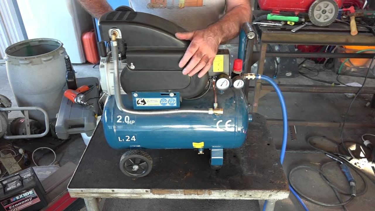
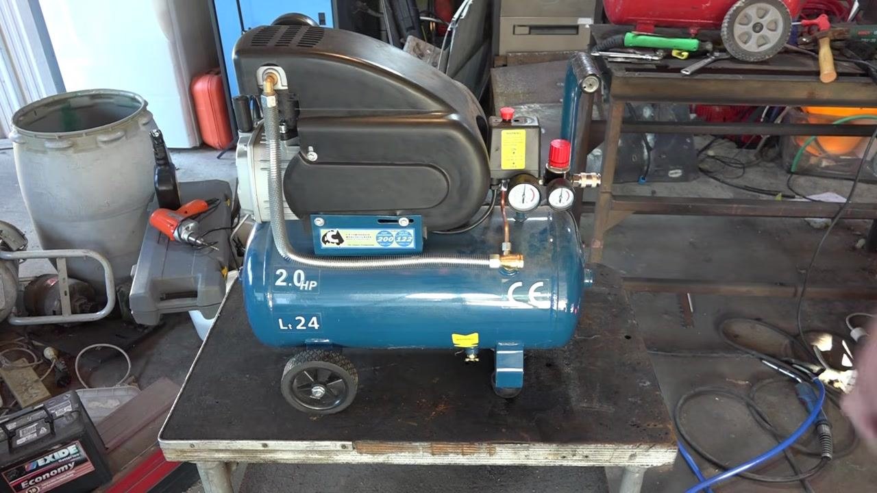
- A smaller 2.0 HP, 24-liter compressor with dual pressure gauges and a single adjustment screw marked with "+" and "–" symbols.
Required tools and PPE
- Phillips screwdriver
- Wrench (for spring-type adjustment screws)
- Personal protective equipment
- Your compressor's manual, for model-specific adjustment instructions and safety warnings

Safety precautions
- Pressure switches are factory set for safe operation. Adjusting them can be dangerous and is not generally recommended unless you are experienced.
- Always unplug the compressor or switch off the circuit breaker before making any adjustment. Confirm there is no electrical current going to the pressure switch to avoid the risk of electric shock.
- Release air from the tank before adjusting to reduce internal pressure and strain on the compressor during restart.
- Make only small, incremental adjustments and monitor the pressure gauges closely after each change.
- Never exceed the pressure limits recommended by the manufacturer.
- Check your compressor for a factory warning label, which typically reads something like: "Pressure controls set at factory for maximum safe operation. Do not adjust factory settings."
Procedure 1: Adjusting a pressure switch with a top screw and balance screw
- Assess the compressor's current condition Check the compressor for signs of aging, such as difficulty reaching previous pressure levels, hard starting, or unusual knocking noises. If the unit struggles to reach 60–70 psi or higher, this is a sign that the maximum pressure setting may need to be reduced.
-
Decide on a new pressure setting Plan to reduce the maximum pressure to approximately 50 psi. This helps prevent overworking the motor and lowers the risk of compressor failure.
-
Start the compressor and observe its operation Turn on the compressor and let it build pressure. Listen for abnormal noises and watch the gauge to see the maximum pressure it currently reaches — in this example, around 60–65 psi. Confirm that the compressor struggles to exceed this level, which indicates that an adjustment is needed.
-
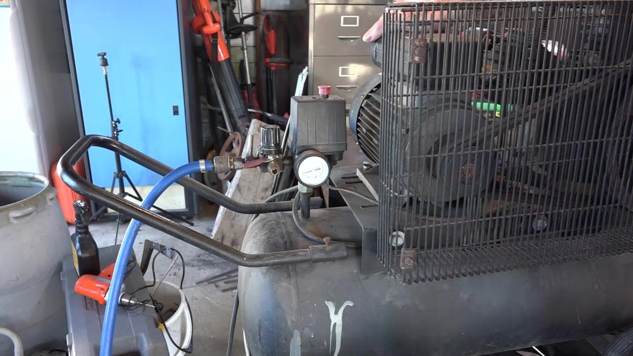
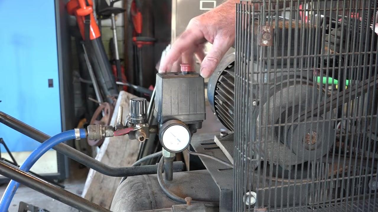
Locate the pressure switch assembly Identify the pressure switch and its adjustment knob or screw, usually located on top of the black housing attached to the compressor tank. Before touching any component, switch off the compressor and unplug it from the power source.
-
Prepare to access the adjustment mechanism Plan to remove the cover from the pressure switch assembly, and gather any tools you may need, such as a screwdriver.
-
Check the current pressure reading Examine the pressure gauge closely to confirm the current maximum pressure, with the needle pointing to approximately 60–65 psi. Note the gauge markings in psi (Lb/in²) and bar (KPa), with the red zone marking higher pressures.
-
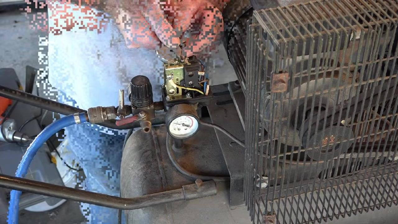
Remove the pressure switch cover Carefully unscrew or unclip the cover from the pressure switch assembly and set it aside in a safe place.
Safety note: The pressure switch is factory set for safety reasons. Adjusting it can be dangerous and should only be attempted if you are experienced.
-
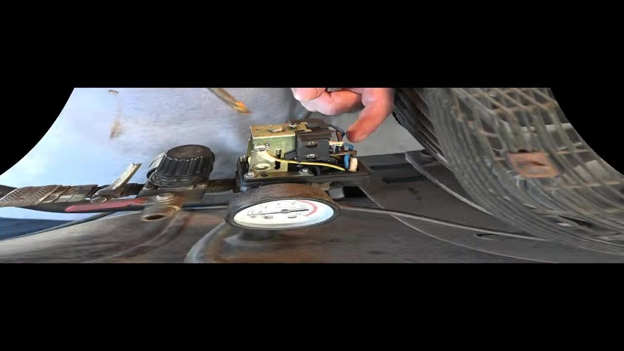
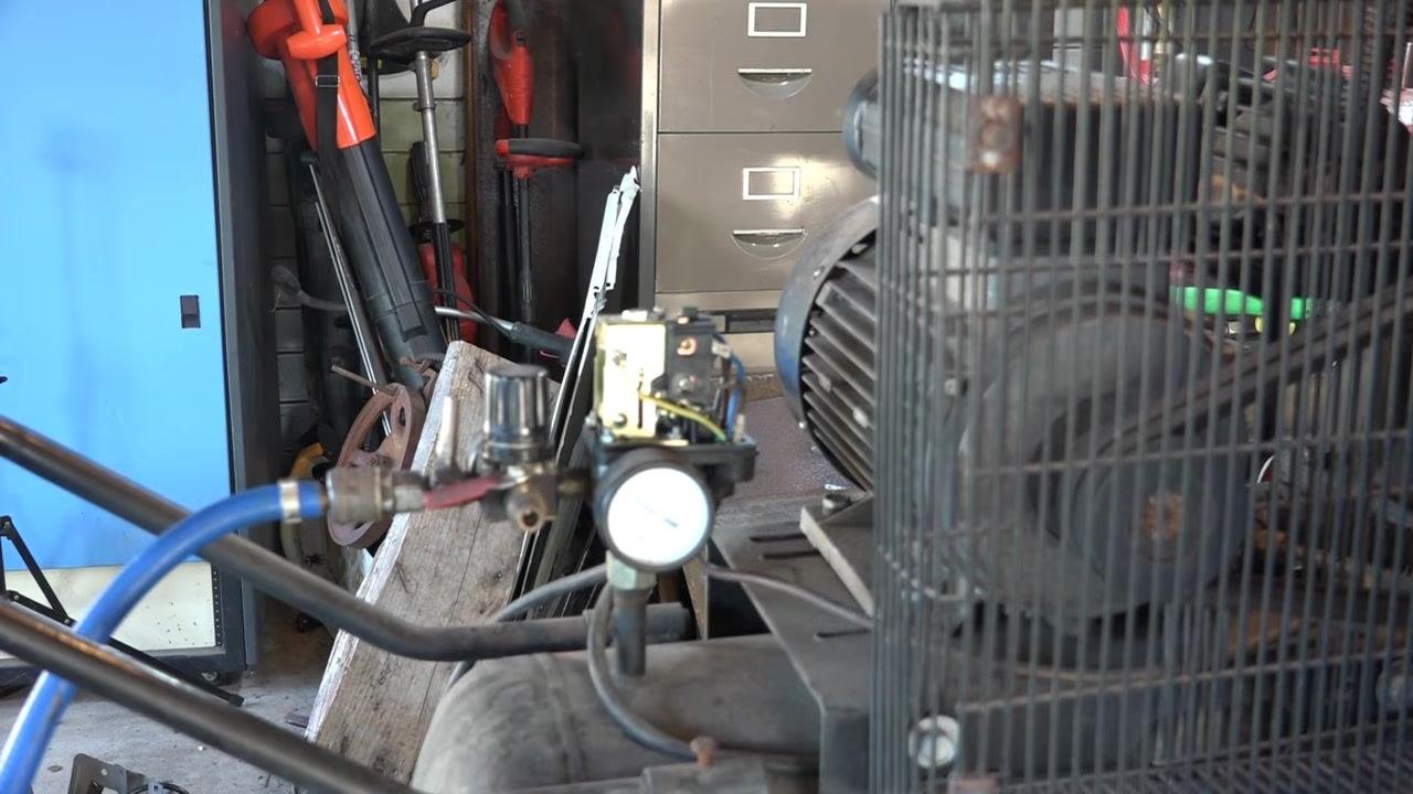
Examine the pressure switch mechanism With the cover removed, observe the internal components: a metal plate, wiring, and one or more adjustment screws or bolts. Some models have a single adjustment bolt on top, while others include an additional screw or nut on the side or bottom.
-
Identify the function of each adjustment screw The screw or bolt on top of the pressure switch controls the maximum pressure, or cut-off point, at which the compressor shuts off. Some models include a second screw — often called the "balance screw" — usually on the side or bottom, which sets the pressure at which the compressor restarts (the cut-in point). If your model has only one adjustment, it typically manages both cut-in and cut-off together, with a fixed differential of about 30 psi.
-
Adjust the maximum pressure (cut-off) Turn the top adjustment screw or bolt counterclockwise to lower the maximum pressure. For example, setting the cut-off to 100 psi will typically cause the compressor to restart at 70 or 60 psi, depending on the fixed differential of your model.
-
Adjust the balance (cut-in) screw, if present If your compressor has a balance screw, use it to set the pressure at which the compressor restarts. For example, setting the cut-in to 50 psi with a 100 psi cut-off produces a 50 psi differential.
-
Understand the spring mechanism Inside the exposed pressure switch, a metal spring is compressed or released by the top adjustment screw. Tightening the screw increases spring tension and raises the cut-off pressure, while loosening it (turning counterclockwise) decreases spring tension and lowers the cut-off pressure. In this example, the gauge currently reads about 60 psi.
-
Turn the adjustment screw to set the new cut-off pressure Use a wrench or screwdriver to turn the adjustment screw clockwise to increase the cut-off pressure, or counterclockwise to decrease it. In this example, the screw is turned to lower the cut-off pressure, targeting a shut-off point around 50 psi.
-
Confirm the compressor is unplugged before adjusting Before turning the screw, verify the compressor is unplugged from the mains or that the circuit breaker is off, to ensure no electrical current is reaching the pressure switch.
-
Release air pressure from the tank Before finalizing the adjustment, release air from the tank to reduce internal pressure. This makes it easier to set the desired cut-off point and reduces strain on the compressor during restart. Continue releasing air to bring the pressure closer to the target of 50 psi.
-
Set the desired cut-off pressure Continue adjusting the screw until the compressor stops at the desired pressure — in this example, just over 50 psi. The gauge should reflect the new cut-off point once the adjustment is complete.
-
Test the adjustment Plug the compressor back in or switch the circuit breaker on. Let the compressor run and watch the gauge to confirm it shuts off at the new setting, around 50 psi. If further adjustment is needed, repeat the process: unplug, release pressure, adjust, and test again.
Safety note: Lowering the cut-off pressure reduces strain on the compressor during startup and may extend its lifespan. Always disconnect power before making any adjustment.
Procedure 2: Adjusting a pressure switch with a single "+/–" screw
-
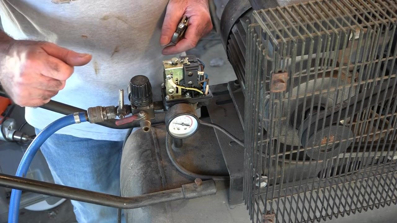
Inspect the main compressor and pressure switch assembly Confirm the compressor is powered off and depressurized. Observe the exposed pressure switch, pressure gauge, regulator, and attached air hose before starting any adjustment.
-
Read the current pressure gauge value Locate the pressure gauge on the compressor. It typically displays measurements in Kg/cm², KPa (bar), and Lb/in² (psi). In this example, the needle points just above 2 Kg/cm² (approximately 30 psi).
-
Continue monitoring the pressure gauge Keep watching the gauge as the compressor operates, confirming that the pressure stays within a safe operating range.
-
Move to the smaller compressor for the second adjustment example This unit is a 2.0 HP compressor with a 24-liter tank and dual pressure gauges, placed on a workbench with tools nearby.
-
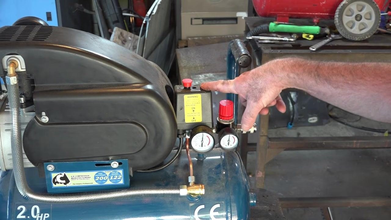
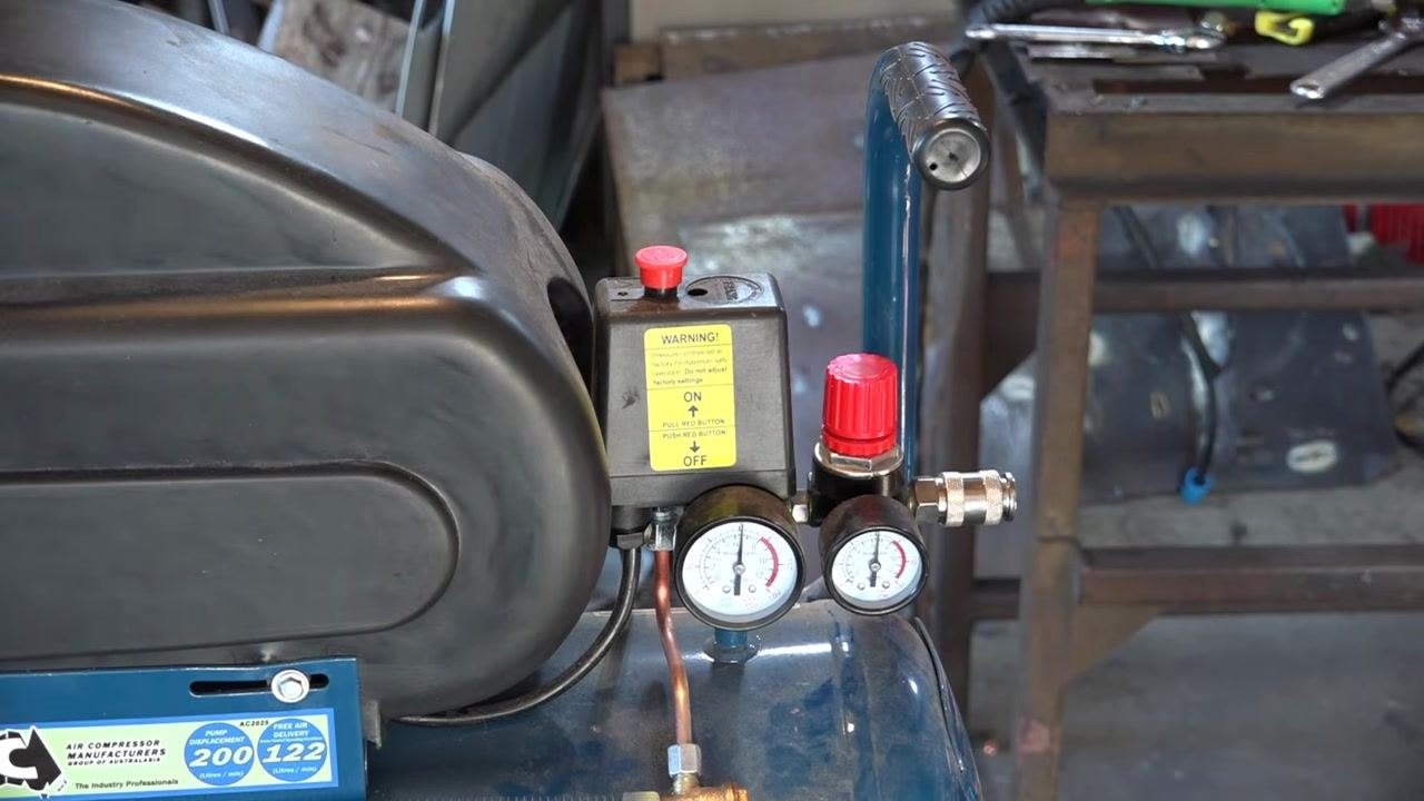
Review the factory warning label Locate the yellow warning label on the pressure switch housing. It typically reads: "Pressure controls set at factory for maximum safe operation. Do not adjust factory settings," along with operating instructions such as "ON: Pull red button. OFF: Push red button." Adjusting factory settings may compromise safety and void your warranty.
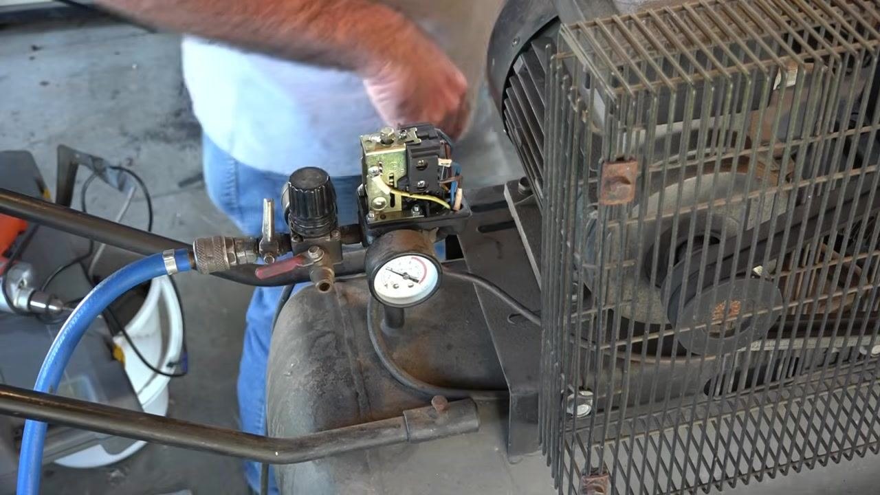
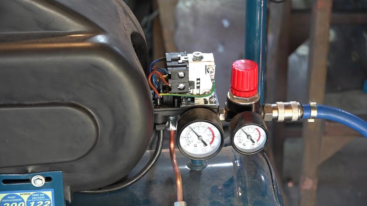
- Identify the pressure switch and regulator controls Locate the pressure switch housing with its red ON/OFF button and the red pressure regulator knob, along with the dual gauges used to monitor tank and regulated output pressure.
Safety note: Increasing pressure beyond factory settings can damage the compressor or create safety hazards, including over-pressurization or premature motor burnout.
-
Review the controls before adjusting Confirm you understand the warning label and the correct operation of the ON/OFF button and regulator before making any changes.
-
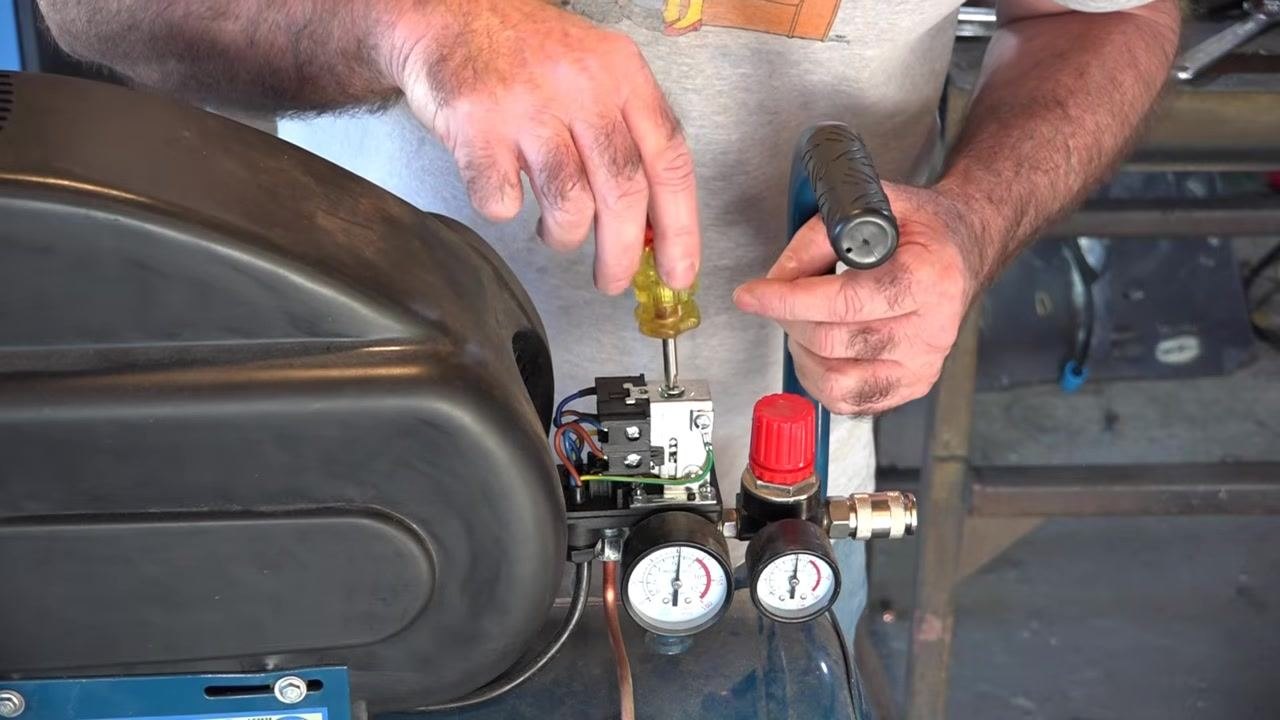
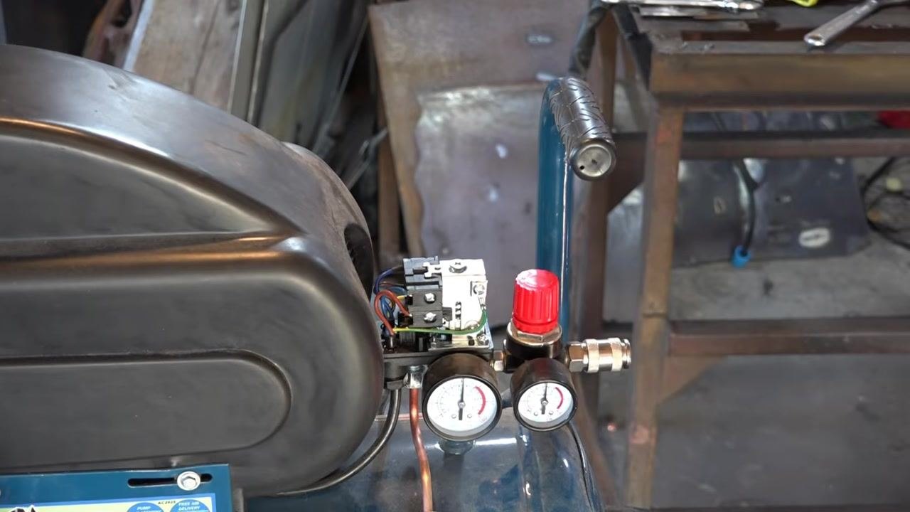
Locate the pressure switch adjustment screw Identify the pressure switch assembly near the dual gauges and red regulator knob, and locate the screw head on top of the switch.
-
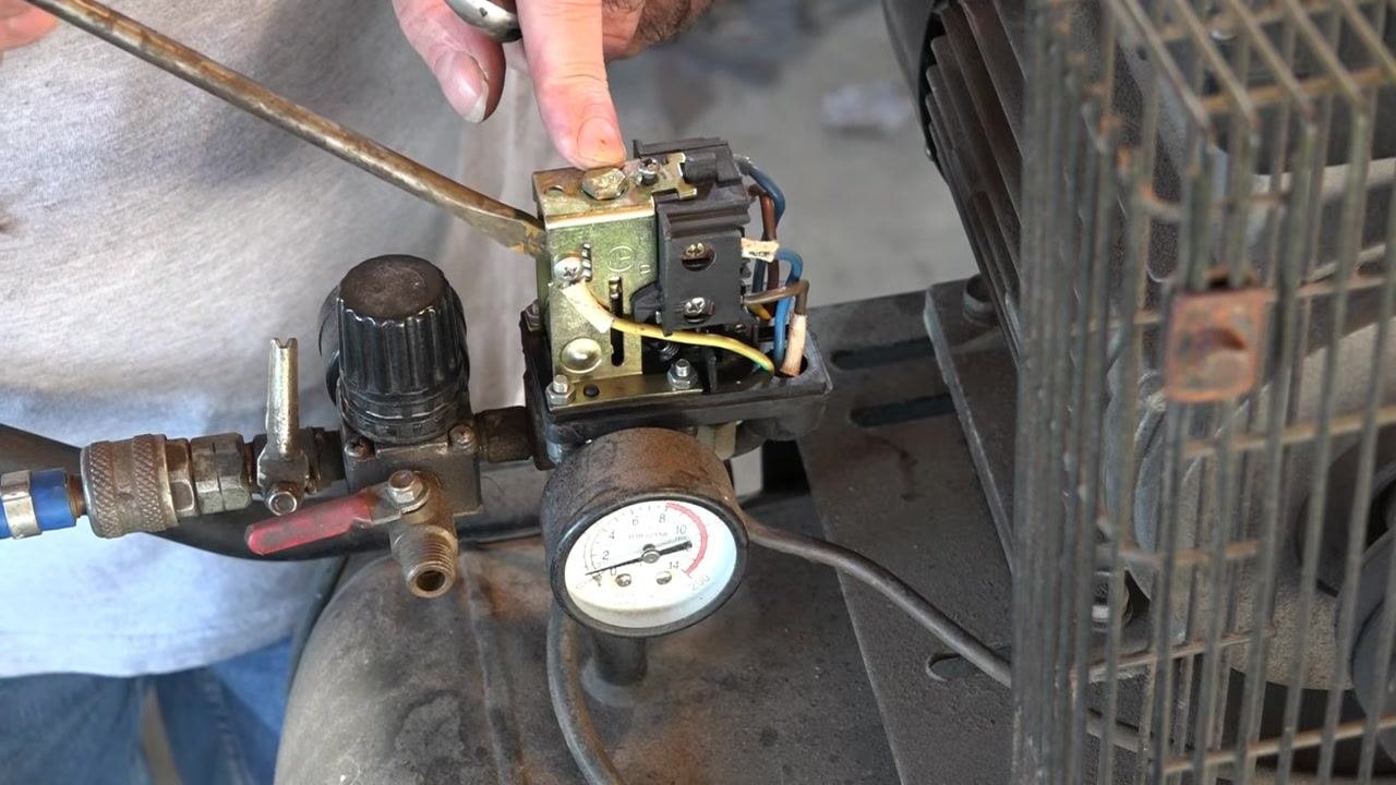
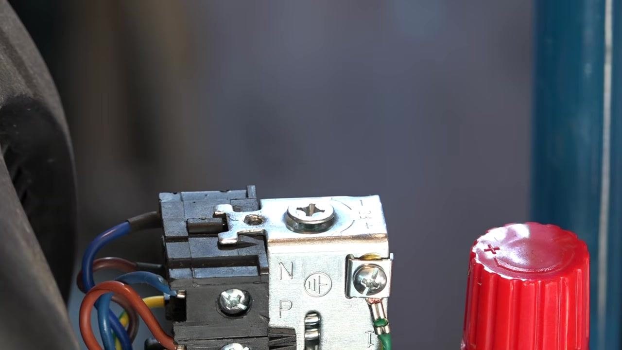
Examine the adjustment screw closely The screw is a Phillips head, and the surrounding metal plate is marked with symbols for reference.
-
Understand the "+" and "–" markings Note the "+" and "–" symbols stamped on the metal plate around the adjustment screw. Turning the screw clockwise, toward "+", increases the pressure setting. Turning it counterclockwise, toward "–", decreases the pressure setting.
-
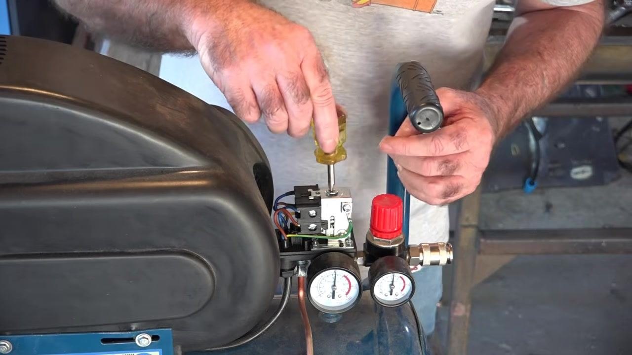
Turn the screw to lower the pressure setting Use the screwdriver to turn the adjustment screw counterclockwise, which decreases the pressure setting. Turning the screw loosens the internal spring, reducing its tension.
-
Observe the reduced spring tension As the screw is turned, the spring inside the pressure switch comes under less tension, corresponding to a lower pressure cut-off setting.
-
Prepare to test the new setting After adjusting the screw, step back and prepare to reconnect power to the compressor to test the new setting.
-
Prepare to drain air from the tank Before testing, prepare to release air from the compressor tank to observe the effect of the new setting. Keep the gauges and regulator in view to monitor pressure changes.
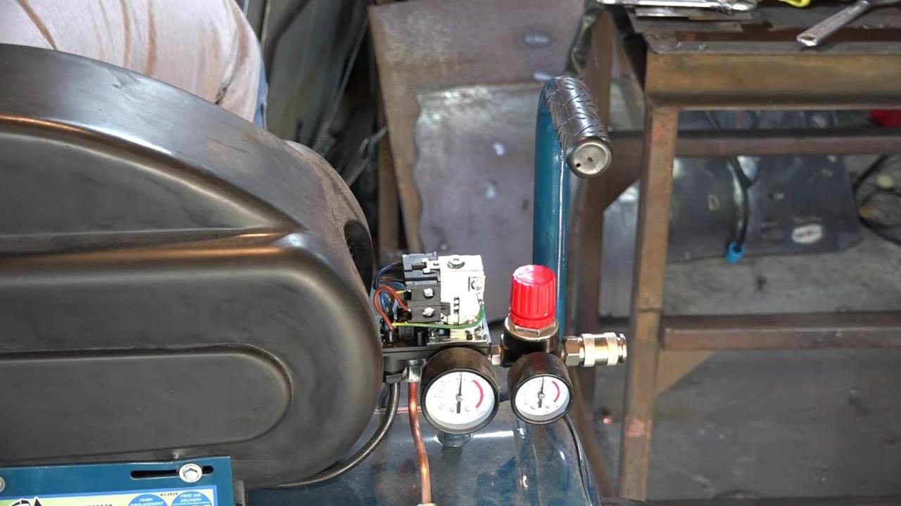
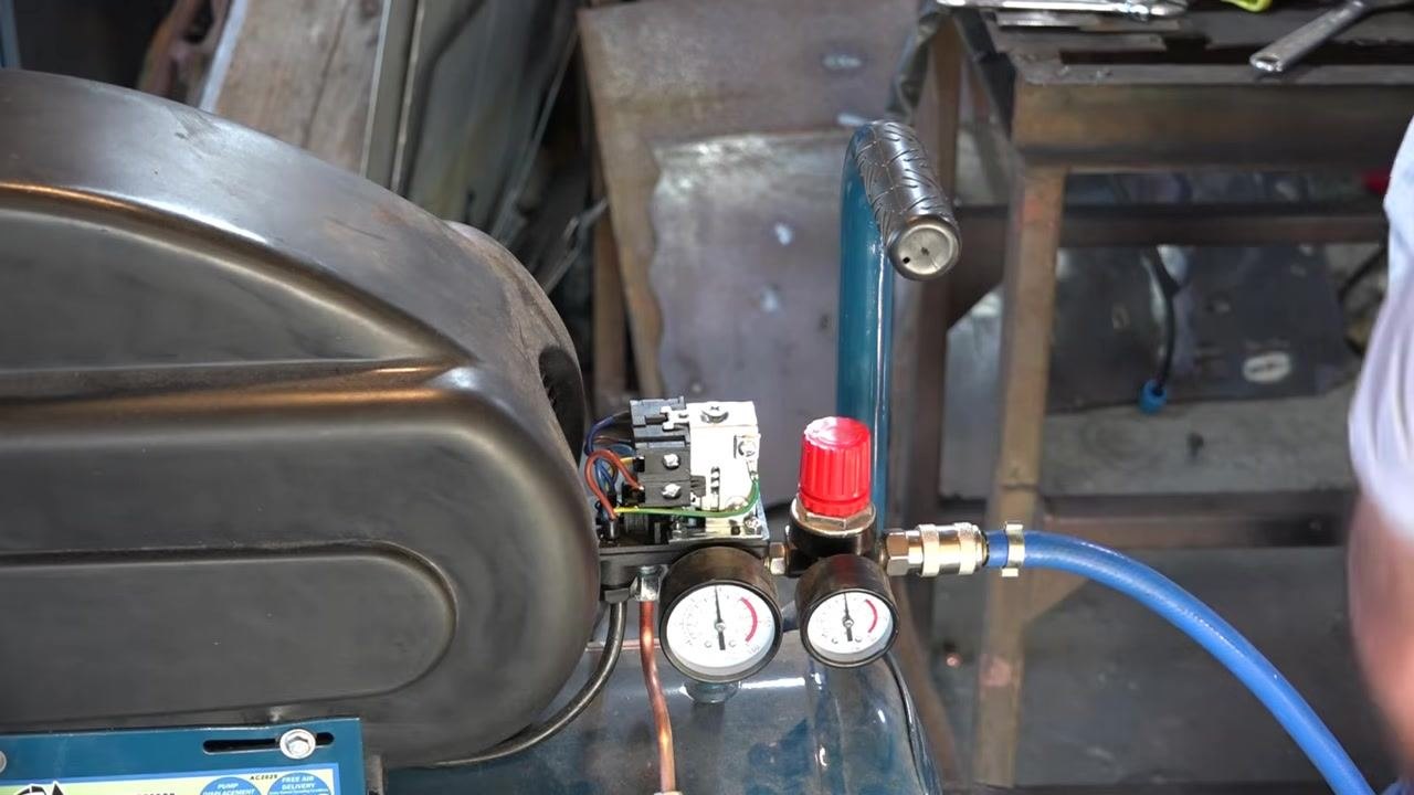
Testing and verifying the new pressure setting
- Release air from the compressor tank Hold the air hose with an attached blow gun, direct the nozzle away from yourself and others, and squeeze the trigger to release air from the tank while watching the pressure gauges.
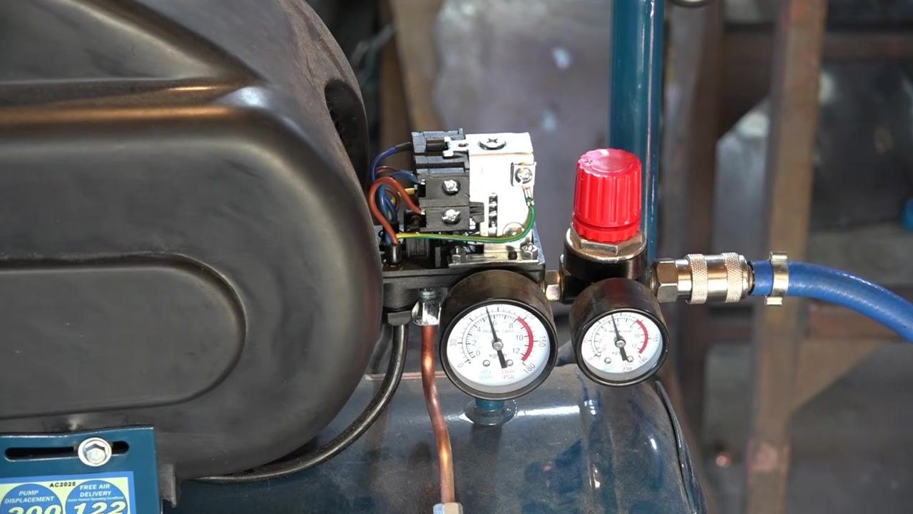
-
Monitor the pressure gauges Watch the left gauge (tank pressure) and the right gauge (regulated output pressure) as air is released. Confirm that the tank pressure drops below 90 psi, verifying the effect of the adjustment.
-
Continue draining air if further reduction is needed If you want to lower the pressure further, continue releasing air with the blow gun while maintaining a safe distance and monitoring the gauges.
-
Check for the lowest achievable setting Continue watching the gauges as pressure drops. Ensure the pressure does not fall below the safe operational range specified by the manufacturer.
-
Bleed off additional air if necessary If needed, repeat the air release process and continue monitoring the gauges until the pressure settles at the new cut-off point.
-
Confirm final pressure stabilization Watch the gauge needle drop and settle to confirm the new cut-off pressure. In this example, the pressure stabilizes at around 70 psi, demonstrating that the adjustment took effect.
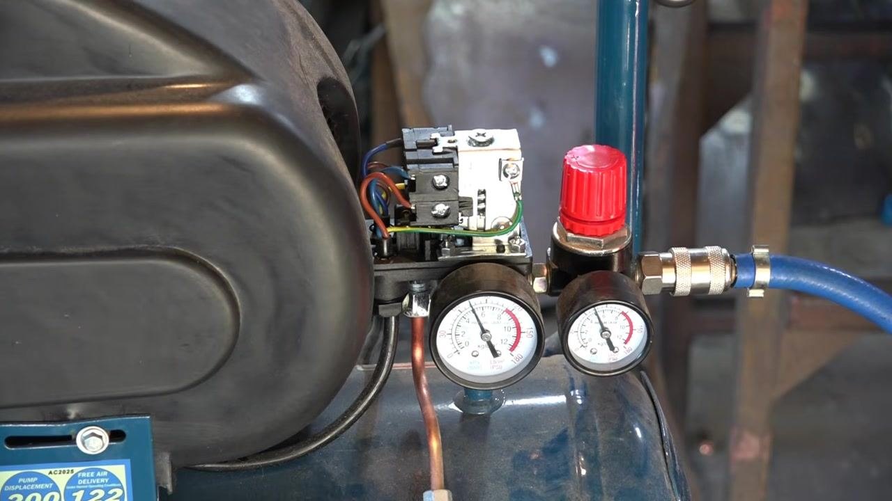

Final safety guidance
- If your pressure switch responds inconsistently or with a delay, this may indicate a faulty switch. Consider replacing it rather than attempting risky adjustments.
- Pressure switches vary in appearance across compressor sizes and brands, but their function and adjustment principles are generally similar.
- Always check for factory warning labels on your compressor's pressure switch. Manufacturers set these controls for safety and equipment longevity, and factory settings should only be adjusted if absolutely necessary and you fully understand the risks.
- Adjusting a pressure switch carries real risk, including the potential for serious injury from over-pressurization, or accelerated wear and failure of the compressor. Only proceed if you are qualified and have taken all necessary safety precautions.
- If you decide to adjust a pressure switch, always unplug the compressor first, use the correct tool (typically a Phillips screwdriver), make only small incremental changes, and monitor results closely after each change.
Verification and summary
- Confirm the compressor shuts off at the new cut-off pressure you set (for example, 50 psi in the older-unit example, or the stabilized reading in the +/– screw example).
- Confirm the compressor restarts at the expected cut-in pressure, based on either the balance screw setting or the fixed differential of your model.
- Recheck the pressure switch cover is securely replaced after adjustment and before returning the compressor to normal use.
- Repeat the unplug–release–adjust–test cycle as many times as needed until the desired settings are achieved.
- Always keep the compressor's manual and manufacturer's safety labels on hand for reference, and never exceed recommended pressure limits.
- For further reference, official manufacturer documentation or trusted tool resources such as PETE'S-TOOLS.COM can provide additional guidance on safe pressure switch adjustment.
Generation details: cost, quality tiers
Docsie billed 5,500 credits ($3.85) to analyze this 11-minute video at standard quality. The rewrite, template fill and Word/PDF exports were included. The same video at each quality tier:
| Quality | Frames sampled | Credits | Approx. cost |
|---|---|---|---|
| Draft | every 16-30 s | 2,750 | $1.92 |
| Standard (this guide) | every 8-15 s | 5,500 | $3.85 |
| Detailed | every 4-7 s | 11,000 | $7.70 |
| Ultra | every 1-3 s | 22,000 | $15.40 |
Credits priced at $0.70 per 1,000; plans include a monthly allowance. Enterprise customers on on-premise or bring-your-own-model deployments run this on their own inference and pay no per-video credits.
Generated by Docsie Video-to-Docs on 2026-09-20 from a 10-minute video. Screenshots are frames from the source video and belong to their creator, pete's tools, whose original is embedded above. If you own this video and want the guide removed or credited differently, contact us and we will act within one business day.