
How to Clean the Carburetor on a Pressure Washer
If a pressure washer has been sitting unused for an extended period, the engine may crank and even spark but fail to keep running — a common symptom of a clogged or gummed-up carburetor. This SOP explains how to clean the carburetor on a pressure washer, using a PowerFlow Plus unit with a Briggs & Stratton 190 cc engine as the reference model. It covers the initial inspection, diagnosing the starting problem, removing and disassembling the carburetor, cleaning its internal passages, reassembling it, and verifying that the engine runs properly afterward.
Video: Power Pressure Washer Carburetor Cleaning/Repair - PowerFlow + Technology - June 9, 2019 by mountainbikekayak (2019). All credit for the demonstration goes to the creator; watch the original on YouTube. The written guide below was generated from this video by Docsie. Creator? Request a change or removal.
If a pressure washer has been sitting unused for an extended period, the engine may crank and even spark but fail to keep running — a common symptom of a clogged or gummed-up carburetor. This SOP explains how to clean the carburetor on a pressure washer, using a PowerFlow Plus unit with a Briggs & Stratton 190 cc engine as the reference model. It covers the initial inspection, diagnosing the starting problem, removing and disassembling the carburetor, cleaning its internal passages, reassembling it, and verifying that the engine runs properly afterward.
Purpose
This procedure provides a step-by-step method for identifying a fuel-delivery problem in a pressure washer engine and resolving it by removing, cleaning, and reinstalling the carburetor. It also documents the inspection points needed to confirm the machine is safe and ready to operate once the repair is complete.
Scope
This SOP applies to a PowerFlow Plus pressure washer equipped with a Briggs & Stratton engine (190 CC, 8.75 gross torque, 3000 max PSI, 5.0 max GPM). The procedure is intended for a nearly new unit that has not been started in over a year and is exhibiting a "won't stay running" condition despite having spark.
Required equipment and PPE
- Screwdriver(s) sized for the engine cover and air filter door screws
- Socket for carburetor mounting hardware
- Aerosol carburetor cleaner
- Clean white towel or absorbent pad to protect the work surface
- Plastic catch container for draining fuel from the float bowl
- Flat, stable outdoor work surface
- Ensure the engine is off and cool before disassembly begins
Initial inspection and equipment overview
Step 1: Identify the equipment and inspect general condition
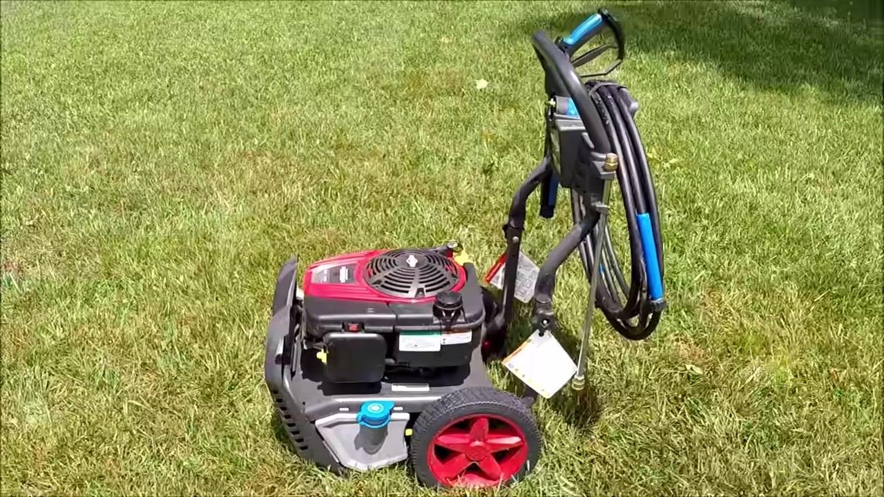
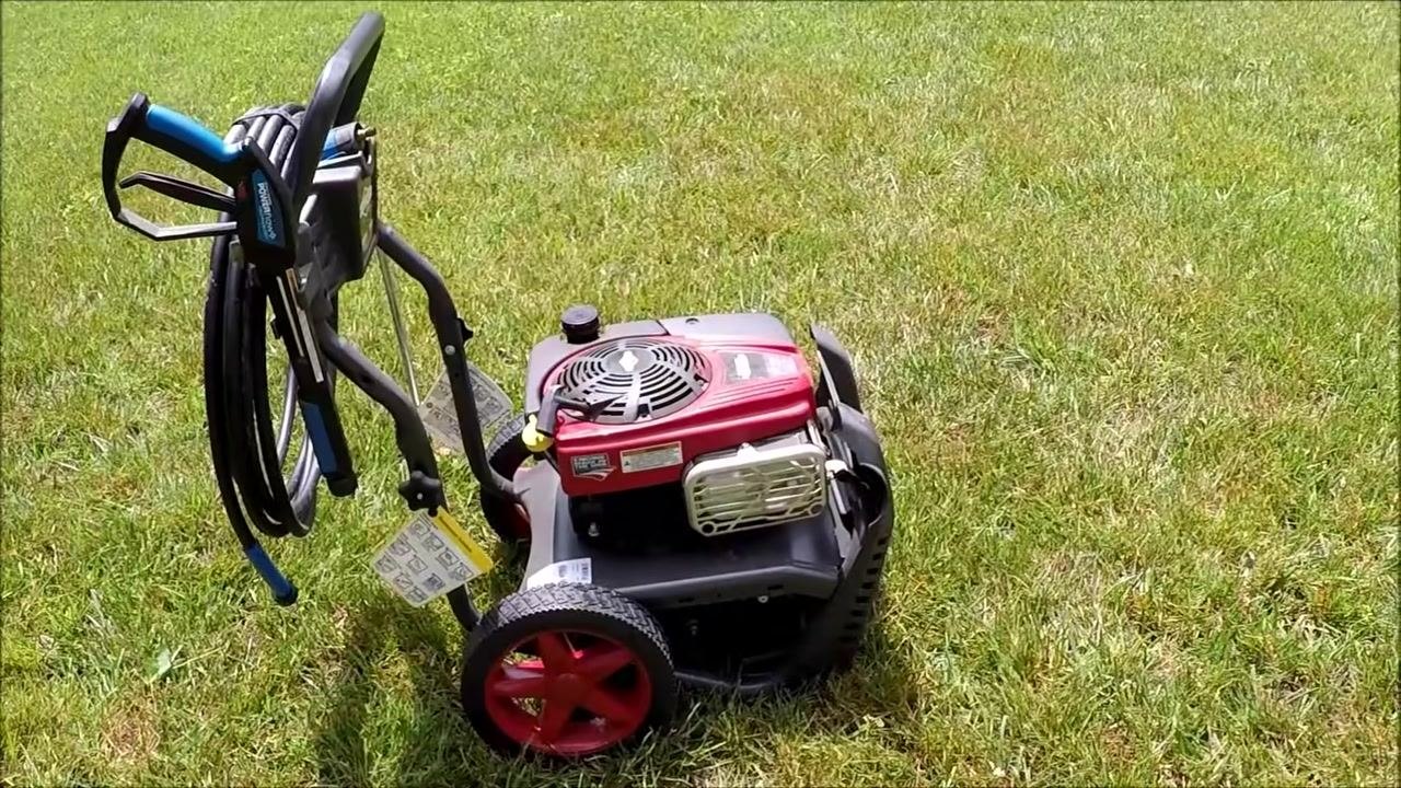
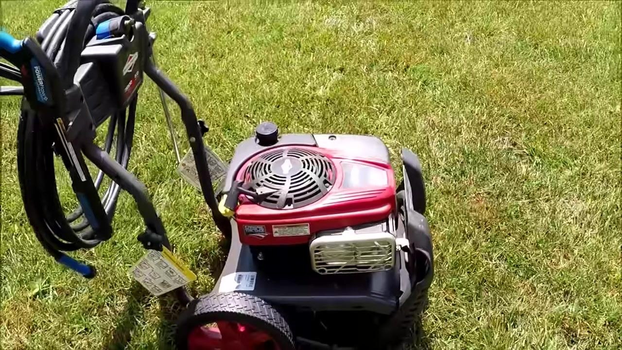
Inspect the PowerFlow Plus pressure washer and confirm it features a Briggs & Stratton engine with the following specifications: 190 CC engine, 8.75 gross torque, 3000 max PSI, and 5.0 max GPM. Confirm the machine is a nearly new model, though it has not been started in over a year, and that it is positioned outdoors on a grassy area.
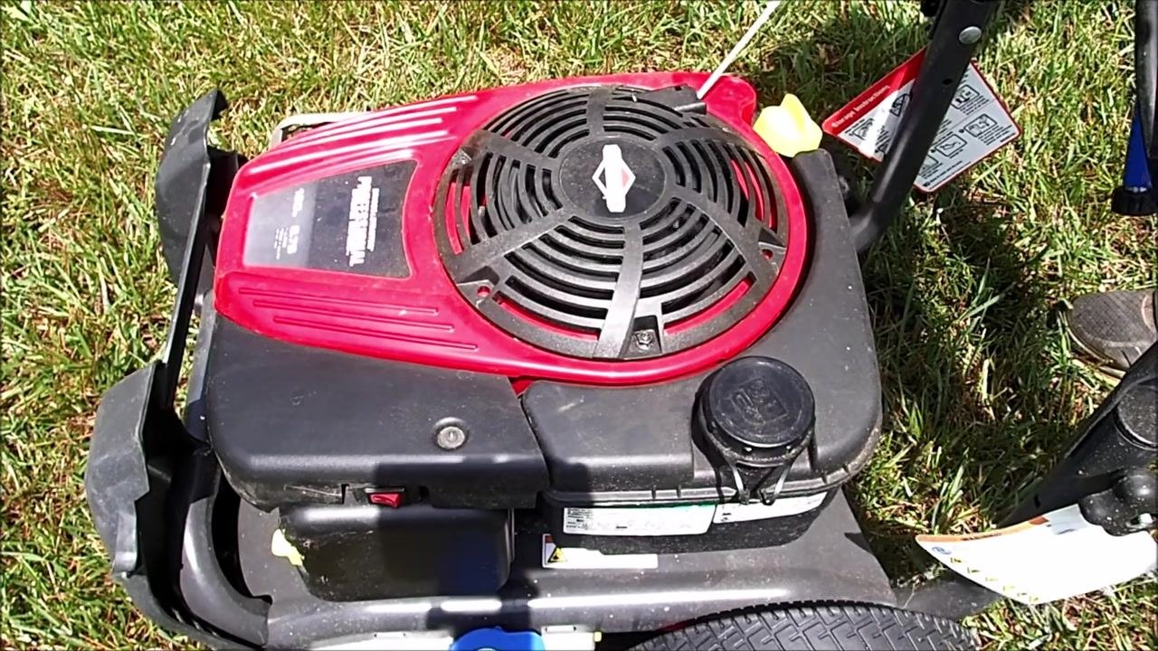
Locate the Briggs & Stratton engine cover and observe the air intake grill and fuel cap.
Walk around the machine to check for visible damage or excessive wear. Confirm the unit appears almost new, with no major signs of use or neglect.
Step 2: Locate the detergent tank
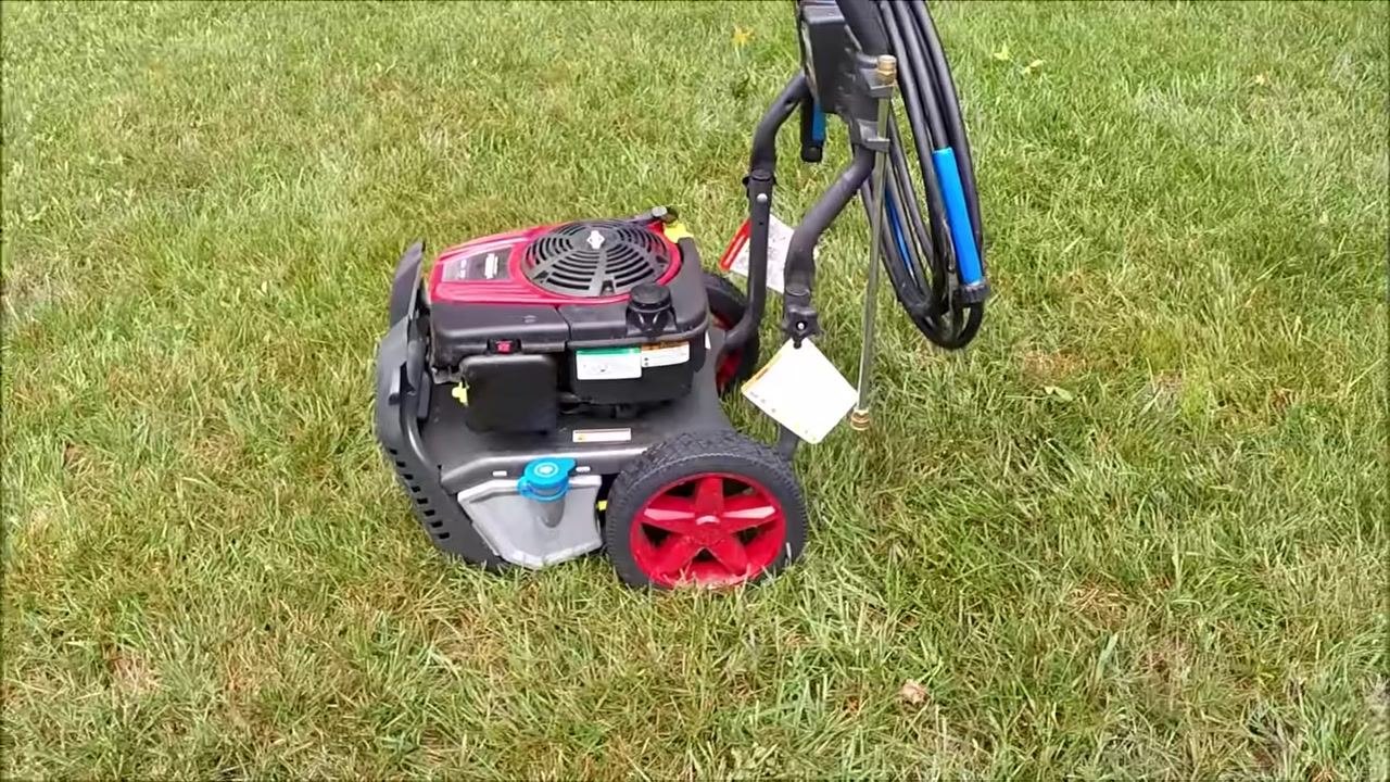
Identify the blue cap on the lower side of the unit as the location for adding cleaning detergent. Ensure the tank is empty and clean before use.
Find the ON/OFF switch on the engine cover, and review the emission control and warning labels for safety and compliance information. Note the engine displacement (190 cc), model year (2016), and EPA Emission Compliance Period (250 hrs).
Step 3: Check the air filter
Open the air filter cover and remove the foam air filter to inspect its condition. Observe whether the foam filter is greasy, which may indicate it requires cleaning or replacement.
Examine the emission control information label for engine family, displacement, and compliance details, and read all warning labels regarding safe operation, gasoline flammability, and carbon monoxide hazards.
Step 4: Evaluate portability
Confirm that the pressure washer is a lightweight model, making it easy to move and transport.
Diagnosing the starting issue
Step 5: Review mobility features and locate the model/serial number
Observe the large rear wheels designed for easy movement across grass and uneven terrain, and confirm the unit is positioned outdoors, ready for troubleshooting.
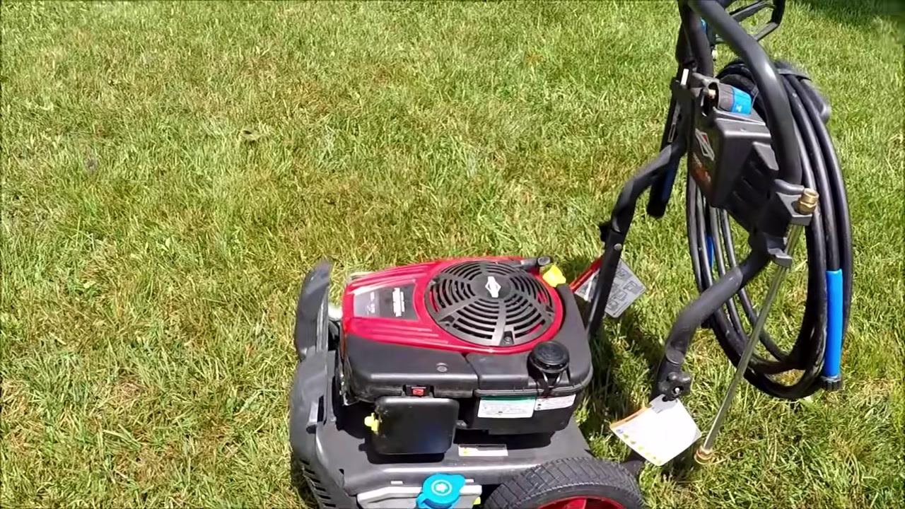
Inspect the engine housing and frame for identification labels, and locate the model and serial number sticker on the lower frame near the rear wheel.
Step 6: Attempt to start the engine and verify spark
Pull the starter cord to attempt to start the engine. Observe that the engine does not start, indicating a potential fuel or ignition issue.
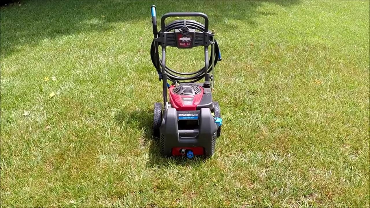
Confirm that the engine has spark. The pressure washer is shown from the front with all major components visible and the hose coiled on the reel.
Step 7: Document the engine details and check the oil level
Identify the engine model and serial number label on the side of the engine housing, noting the model year (2016) and other compliance information for future reference.
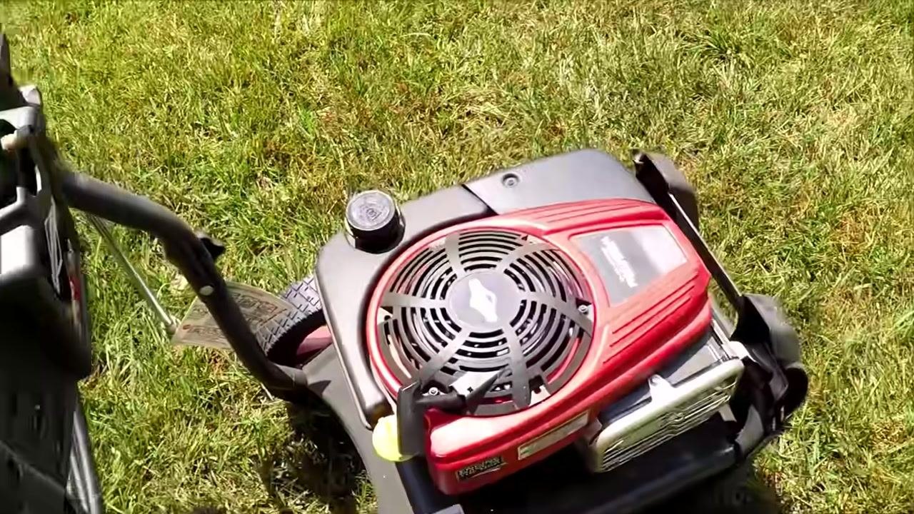
Remove the oil fill cap and dipstick, and inspect the oil level to confirm it reaches the top of the notch on the dipstick as required. Confirm the engine is equipped with an automatic choke.
Step 8: Retest the engine and apply carburetor cleaner
Reinstall the oil cap and attempt to start the engine as-is. Observe that the engine still does not start, confirming the issue persists.
Decide to use carburetor cleaner to test whether the engine will attempt to start, which would indicate a fuel delivery issue. Ensure the engine is off and cool before proceeding. Spray a small amount of carburetor cleaner into the air intake or carburetor opening, and confirm the choke is not stuck by manually moving it.
Step 9: Reattempt starting after applying carburetor cleaner
Pull the starter cord again to try starting the engine after spraying carburetor cleaner. Observe that the engine may briefly attempt to run but will not stay running. Repeat the attempt to confirm the issue persists; the engine only sputters or briefly fires, indicating a likely fuel delivery problem.
Listen for the engine attempting to start but failing to continue running. Confirm that repeated attempts yield the same result, which suggests a blockage or issue within the carburetor.
Preparing to remove the carburetor
Step 10: Remove the top engine cover
Decide to remove and clean the carburetor to address the suspected internal blockage. Identify that the top engine cover and the air filter door must be removed for access, and locate the screws securing both. Ensure the engine is off and cool before proceeding.
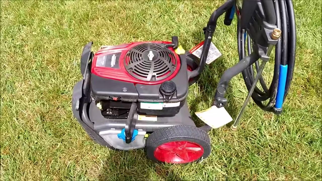
Use a suitable screwdriver to remove the visible screws on the top engine cover, then carefully lift off the cover to expose the carburetor area. Take note of the choke mechanism, as it may be sticking and contributing to the issue.
Step 11: Remove the air filter door
Locate the air filter door on the side of the engine housing, and identify and remove the screws securing it. Gently pull off the air filter door to reveal the air filter and carburetor. Observe the green foam air filter and check for cleanliness or debris.
Step 12: Inspect the air filter and carburetor area
Confirm that the air filter and surrounding area appear clean. Identify the location of the ON/OFF switch on the air filter door assembly, and note the wiring and linkage connections for reference during reassembly.
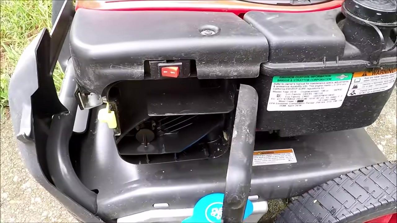
Identify the screws and clamps securing the carburetor to the engine, prepare to clamp the fuel line to prevent spills, and note the throttle and choke linkage positions for correct reinstallation.
Step 13: Set aside the air filter door assembly
Carefully move the air filter door assembly out of the immediate work area. Leave the electrical wires attached to the assembly rather than disconnecting them, and position it so it does not interfere with further disassembly steps.
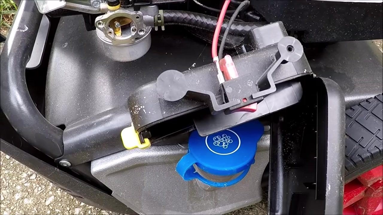
Removing the carburetor
Step 14: Disconnect the carburetor linkage
Disconnect the carburetor linkage from the engine. Observe the carburetor still attached to the engine, with linkage and springs visible, and ensure all connections to the carburetor are removed before proceeding.
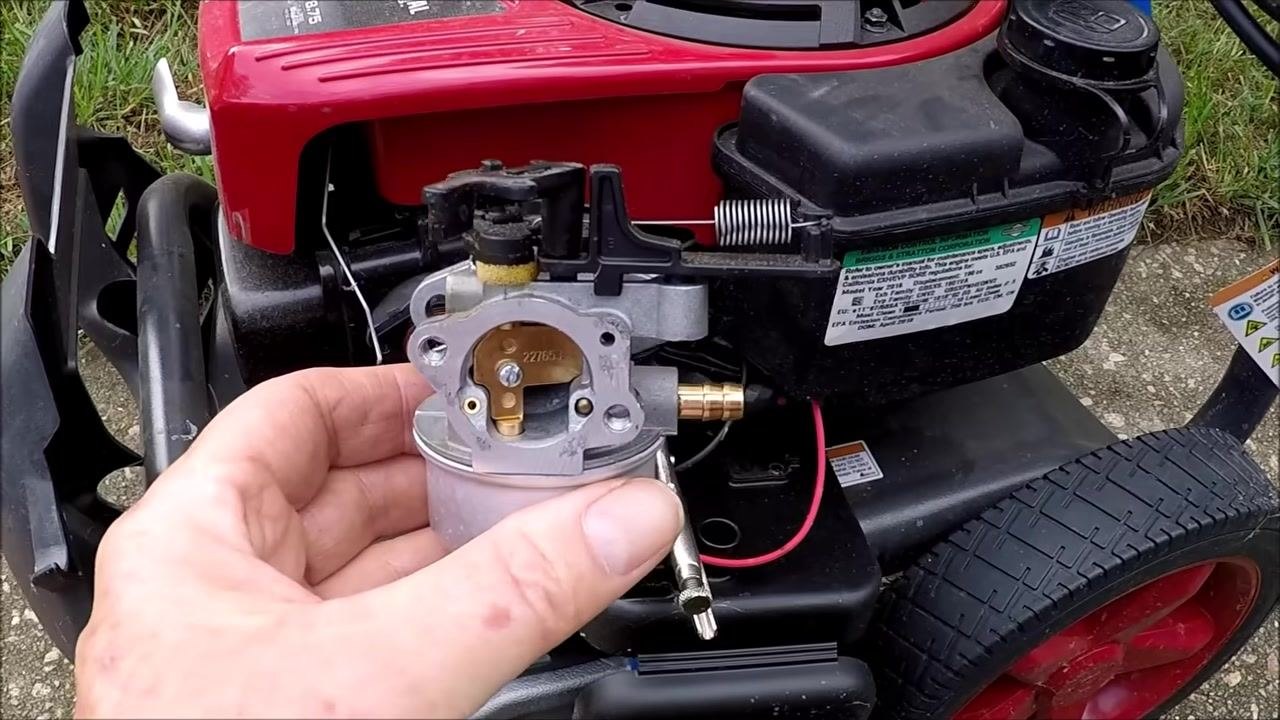
Step 15: Remove the carburetor from the engine
Hold the carburetor firmly and pull it away from the engine. Inspect the removed carburetor for any visible blockages or debris.
Cleaning the carburetor
Step 16: Prepare a clean workspace and remove the float bowl
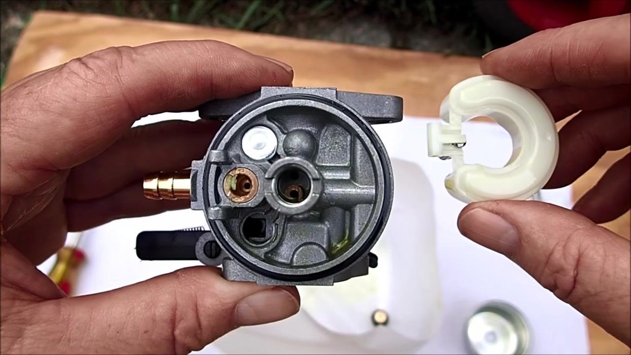
Place a white towel or absorbent pad on a flat surface, and gather the necessary tools, such as a screwdriver. Hold the carburetor in one hand and use the other hand to unscrew the bolt at the bottom of the float bowl.
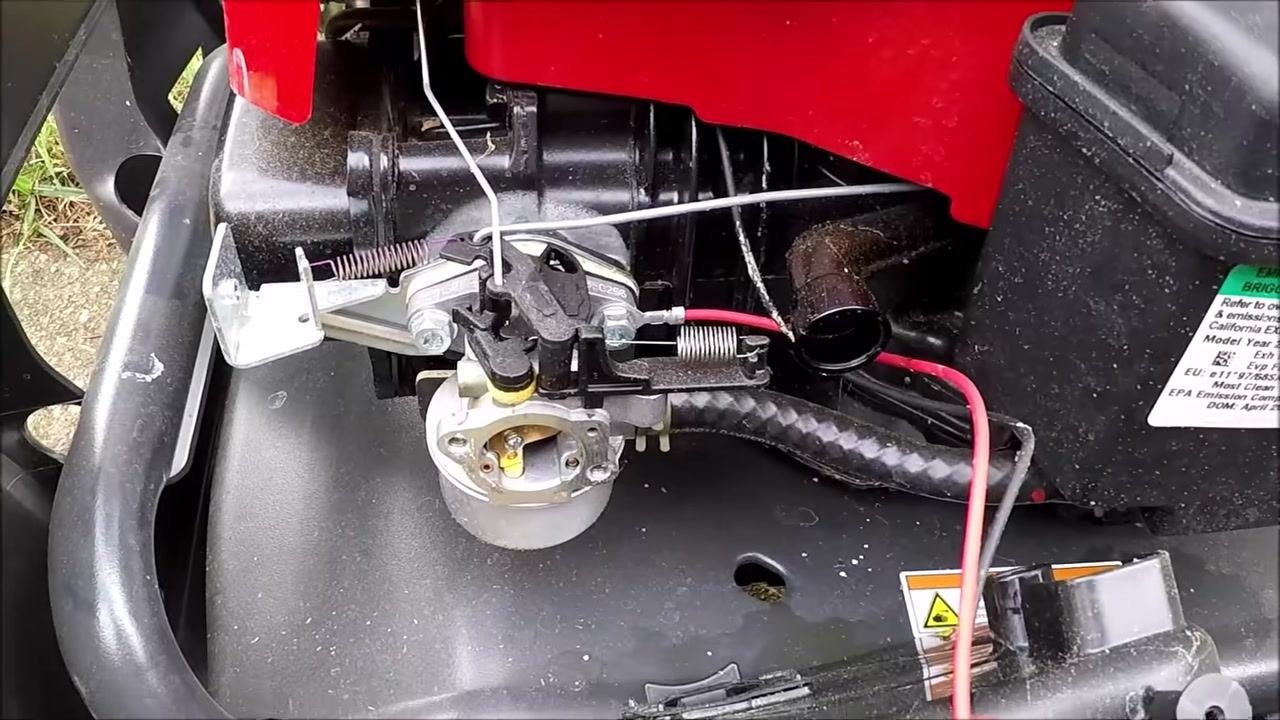
Step 17: Drain the float bowl contents
Tilt the carburetor so any fuel or residue in the bowl empties into a plastic catch container. Observe the fluid for unusual color or oiliness, which may indicate contamination.
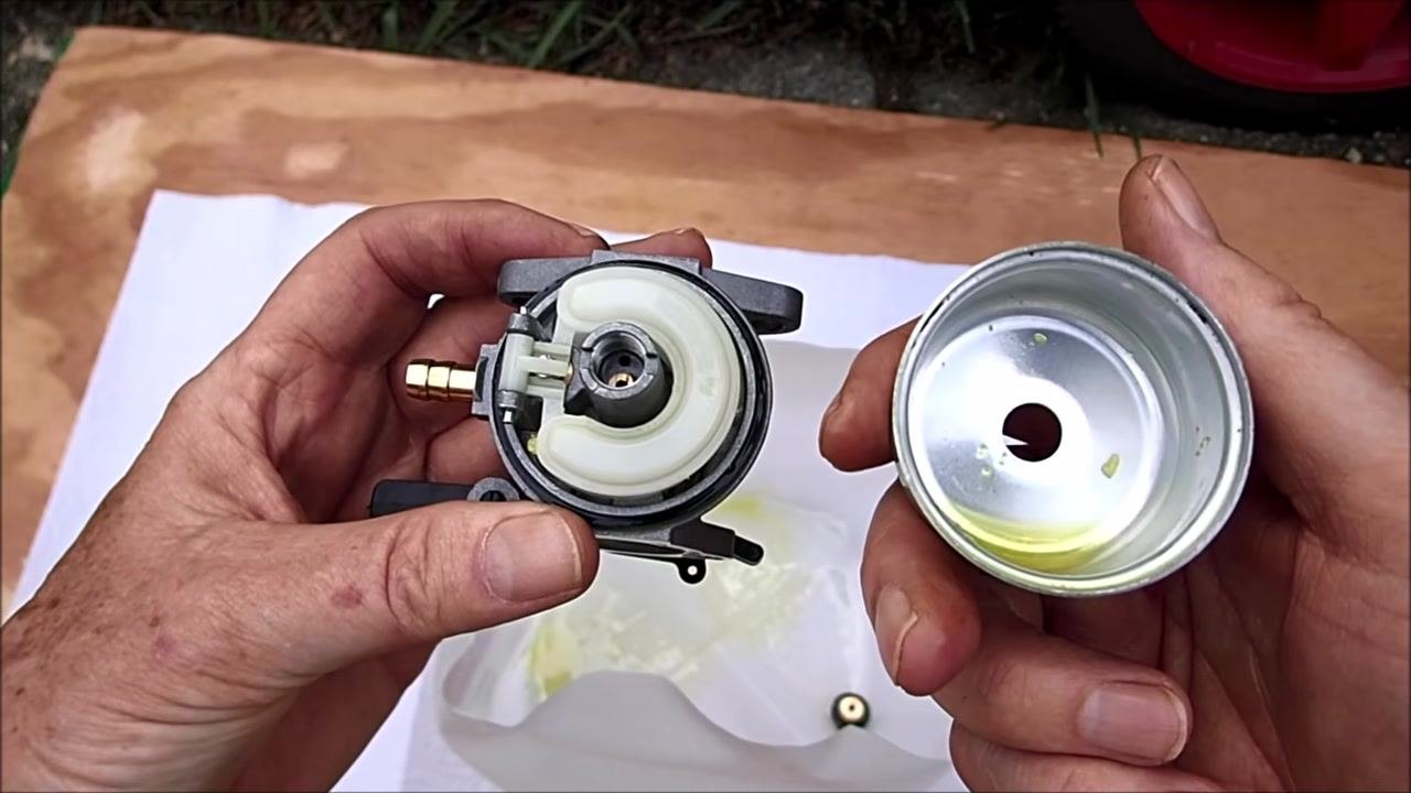
Step 18: Inspect the float bowl and float
Examine the float bowl for debris, varnish, or discoloration, and check the float for smooth movement and cleanliness.
Visually inspect the carburetor body and float bowl for signs of dirt or buildup. A clean carburetor is essential for proper engine function.
Step 19: Inspect the main jet for blockages
Look closely at the brass jet inside the carburetor and check for signs of clogging or residue. If the jet appears plugged, plan to clean it thoroughly.
Step 20: Remove the float and prepare to clean all passages
Carefully lift the float out of its position to expose the needle and seat area, and set it aside on a clean surface.
Ensure all parts are disassembled and laid out for inspection, and plan to use compressed air or carburetor cleaner to clear all fuel and air passages. This is the point where blockages are most likely to be found and cleared.
Reassembling the carburetor
Step 21: Lay out the clean components
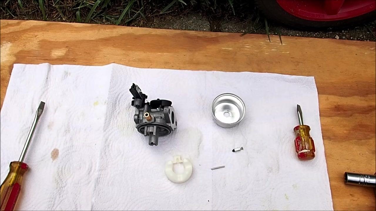
Lay out all components on a clean white towel: the carburetor body, float bowl, float, float pin, needle, and the necessary tools (two screwdrivers, a socket). Ensure the work area is organized and free of debris.
Hold the carburetor and visually check that you can see through the jet hole, confirming the blockage has been cleared and the passage is open.
Step 22: Reinstall the float and needle
Insert the needle into its seat in the carburetor body, position the float in place, and secure it with the float pin. Verify that the float moves freely and seats properly.
Step 23: Attach the float bowl and test float operation
Place the float bowl over the float, align it with the carburetor body, and secure it with the retaining bolt or screw, ensuring a tight seal to prevent leaks.
Hold the carburetor in the correct orientation and observe the float position, then turn the carburetor upside down to confirm the float closes the needle valve, preventing fuel flow. This confirms the float mechanism functions correctly and will cut off fuel when the bowl is full.
Confirm all screws and bolts are tightened, and double-check that all parts are correctly installed and the float mechanism operates smoothly.
Reinstalling and testing the carburetor
Step 24: Reinstall the carburetor onto the engine
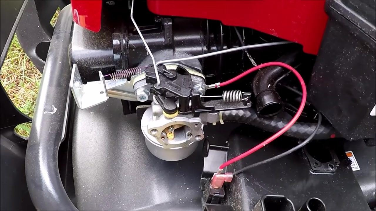
Attach the carburetor to the engine mounting point, reconnect the fuel line, and ensure it is secure and free of leaks. Reattach all linkage and springs as originally configured, and confirm any electrical connections are properly reconnected.
Step 25: Verify springs and linkages
Inspect the carburetor assembly for the presence of all springs, especially any small ones that may have been removed. Ensure the throttle and choke linkages move freely and return to their resting positions.
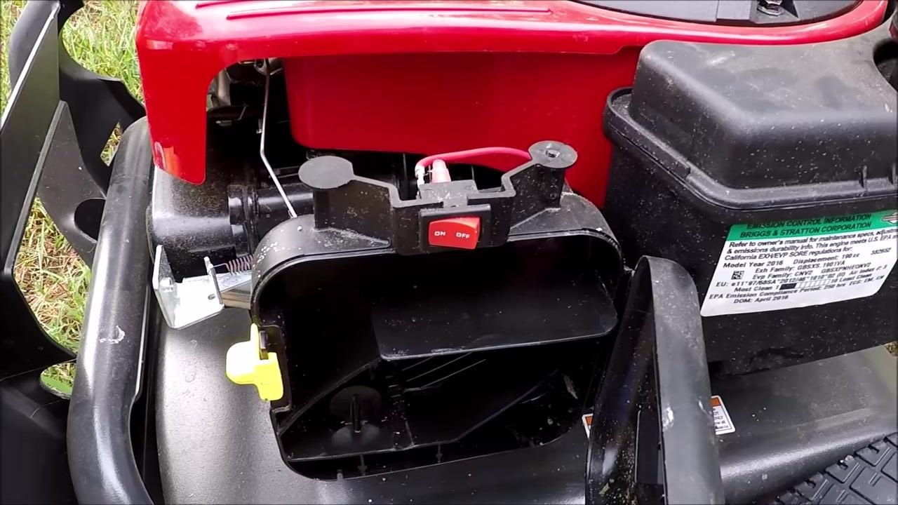
Step 26: Inspect the air filter housing
Open the air filter housing and check the air filter for oiliness or contamination. If the air filter is oily, clean or replace it as needed to ensure proper airflow.
Step 27: Prepare the power washer for testing
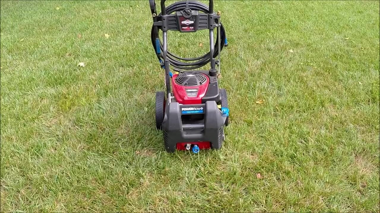
Move the power washer to an open, grassy area, and ensure all connections are secure and the unit is stable on the ground.
Start the engine to test the cleaned carburetor. Observe the engine for smooth operation, absence of leaks, and proper throttle response.
Final testing and confirmation
Step 28: Inspect the engine cover and controls before starting
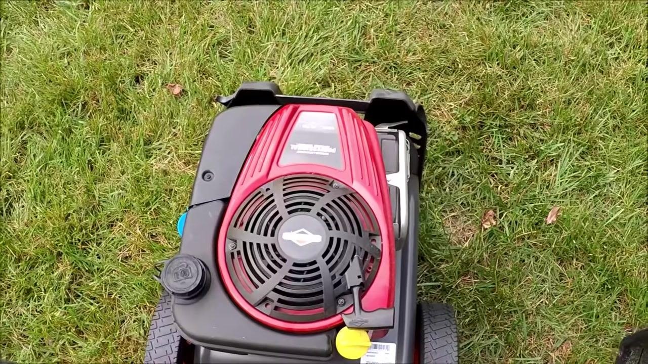
Observe the power washer placed on a grassy area. The engine cover is red with a black vented section and a Briggs & Stratton logo; the fuel cap is on the left, and the pull start handle is at the lower right. Ensure all covers are secured and the area around the engine is clear.
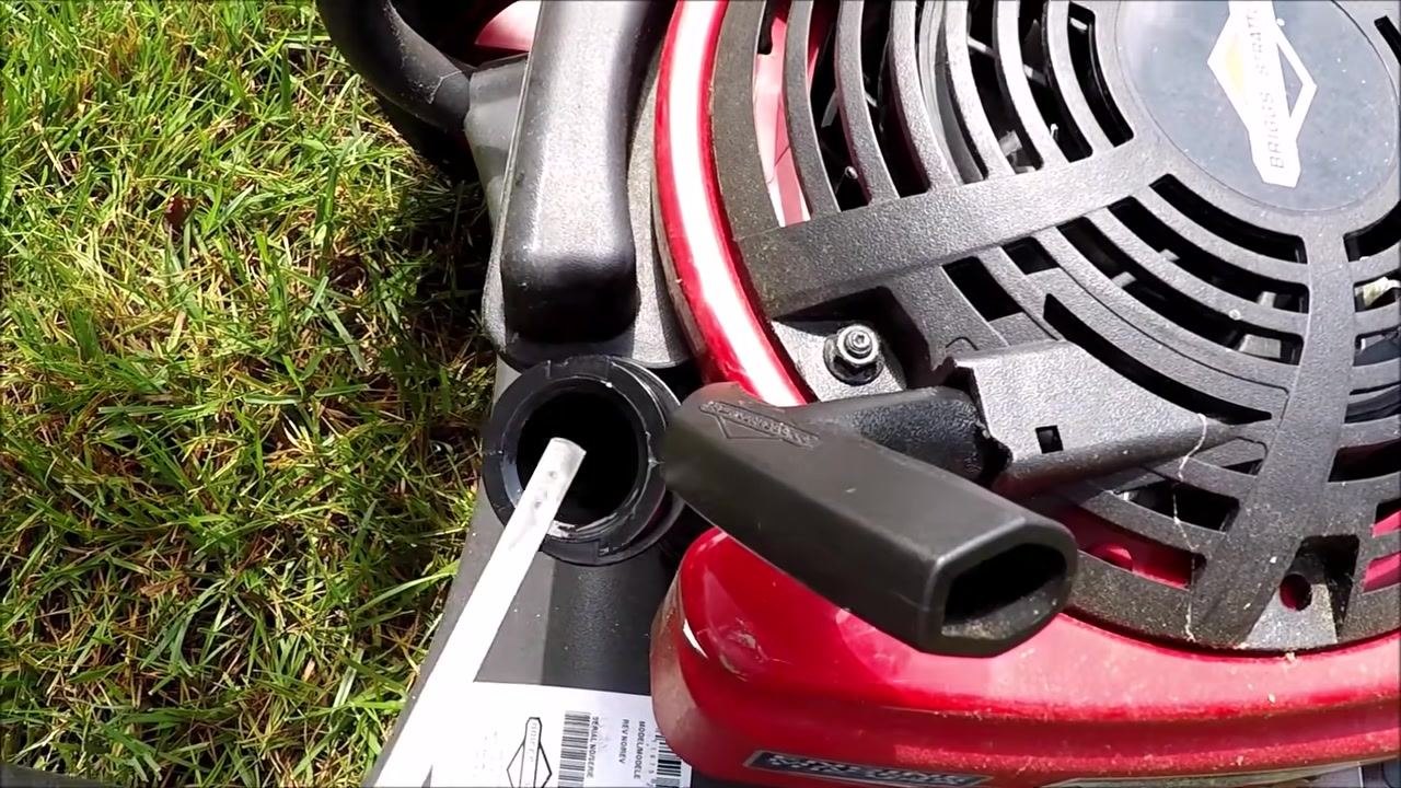
Step 29: Confirm all caps and controls are in place
Check that the oil fill cap (yellow) and fuel cap (black) are tightly secured, and verify that the pull start handle is accessible and the engine is ready for starting.
Examine the side of the engine for emission control information and warning labels. Note the blue cap for the detergent tank and the red wheel for mobility, and read all safety and operational warnings before proceeding.
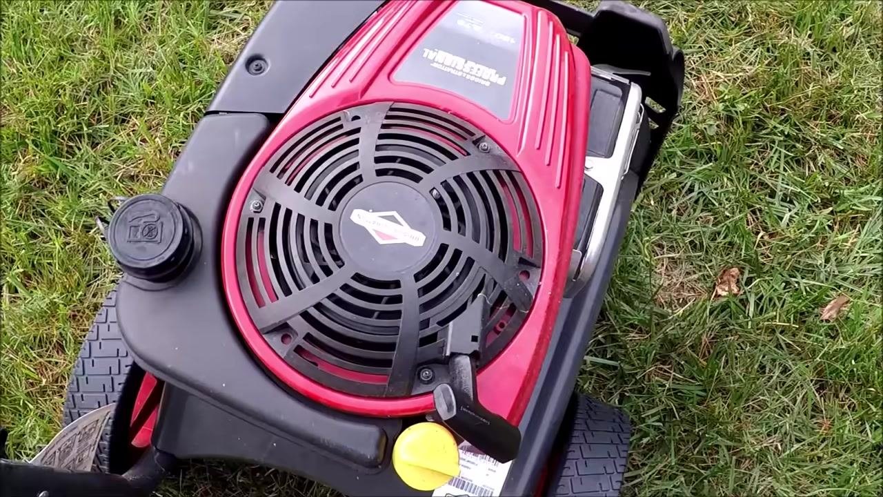
Step 30: Start the engine and observe its operation
Pull the starter cord to start the engine. Listen for smooth running and check for any unusual noises or vibrations.
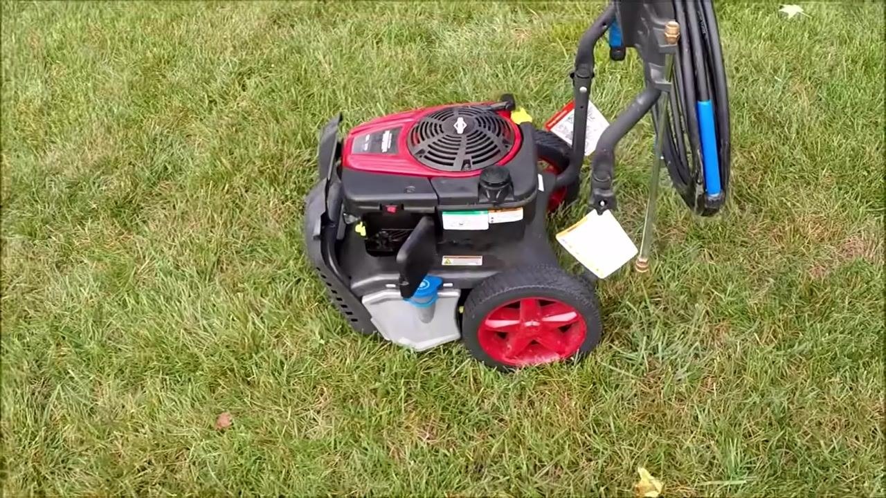
Step 31: Inspect the air filter housing and ON/OFF switch during operation
Open the air filter housing to ensure the filter is properly seated, and confirm the ON/OFF switch is in the correct position for operation while the engine is running.
Step 32: Confirm engine performance
Observe the power washer from a distance to ensure it continues to run smoothly.
Step 33: Inspect the exhaust and engine components
Examine the exhaust cover labeled "Briggs & Stratton" for any signs of leaks or excessive heat, and check for warning labels such as "ENGINE MADE IN THE USA" and fire hazard warnings. Ensure all engine components are secure and functioning.
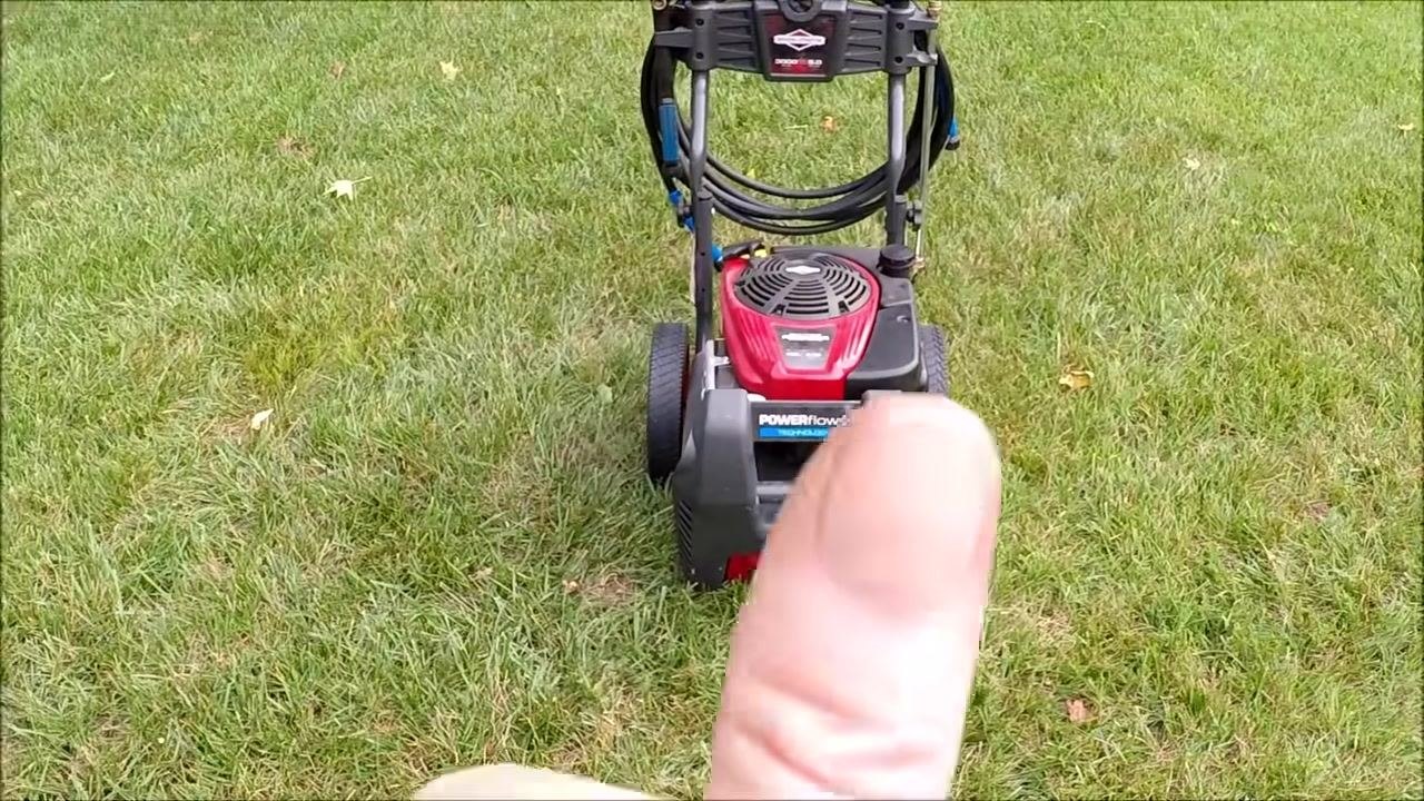
Step 34: Perform a final operational check
Walk around the power washer to ensure there are no leaks, loose parts, or abnormal sounds while the engine is running, and confirm the unit is ready for use or storage.
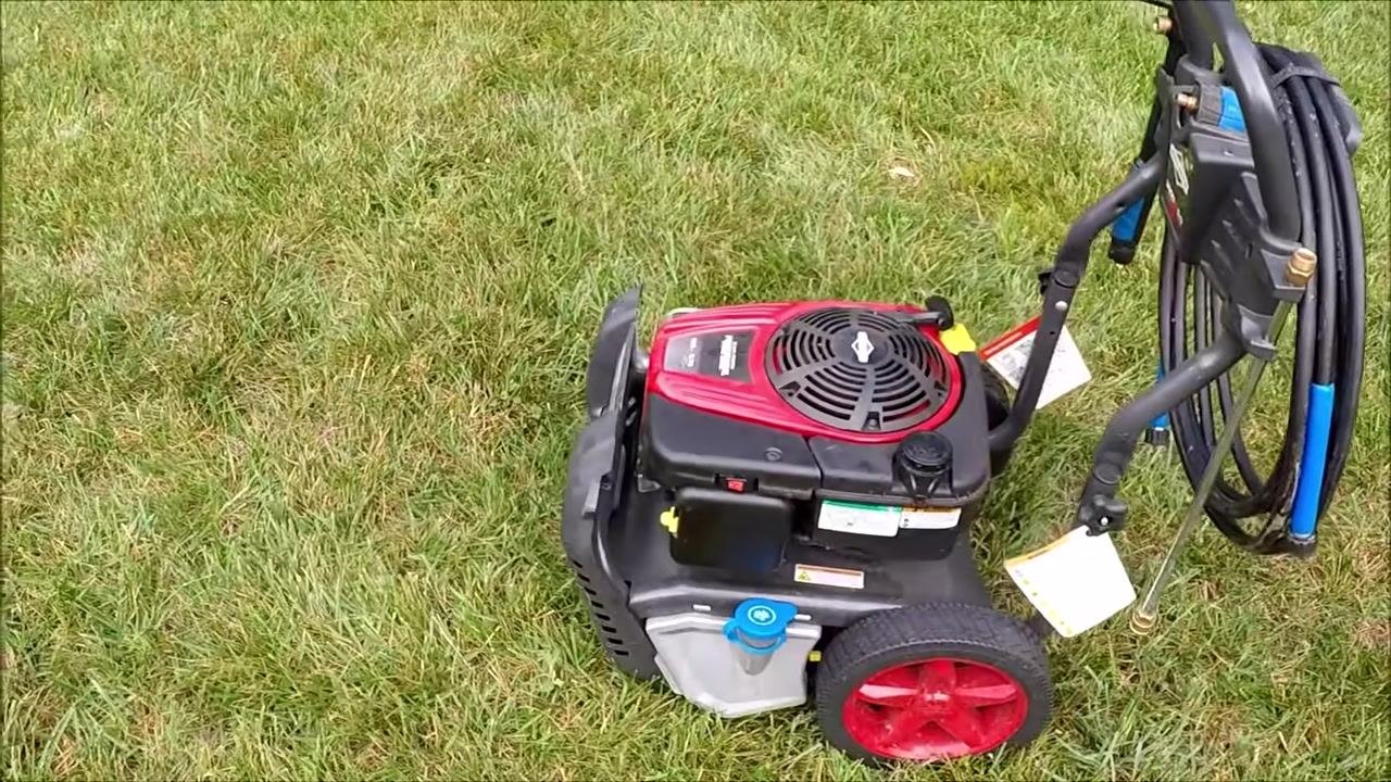
Final inspection and overview
Step 35: Inspect the engine and controls
Observe the Briggs & Stratton engine with its red and black cover, and note the visible labels, including emission control information, warning labels, and a maintenance schedule tag. Identify the ON/OFF switch (red button), oil cap, and fuel cap, and ensure all components are securely attached with no visible leaks or damage.
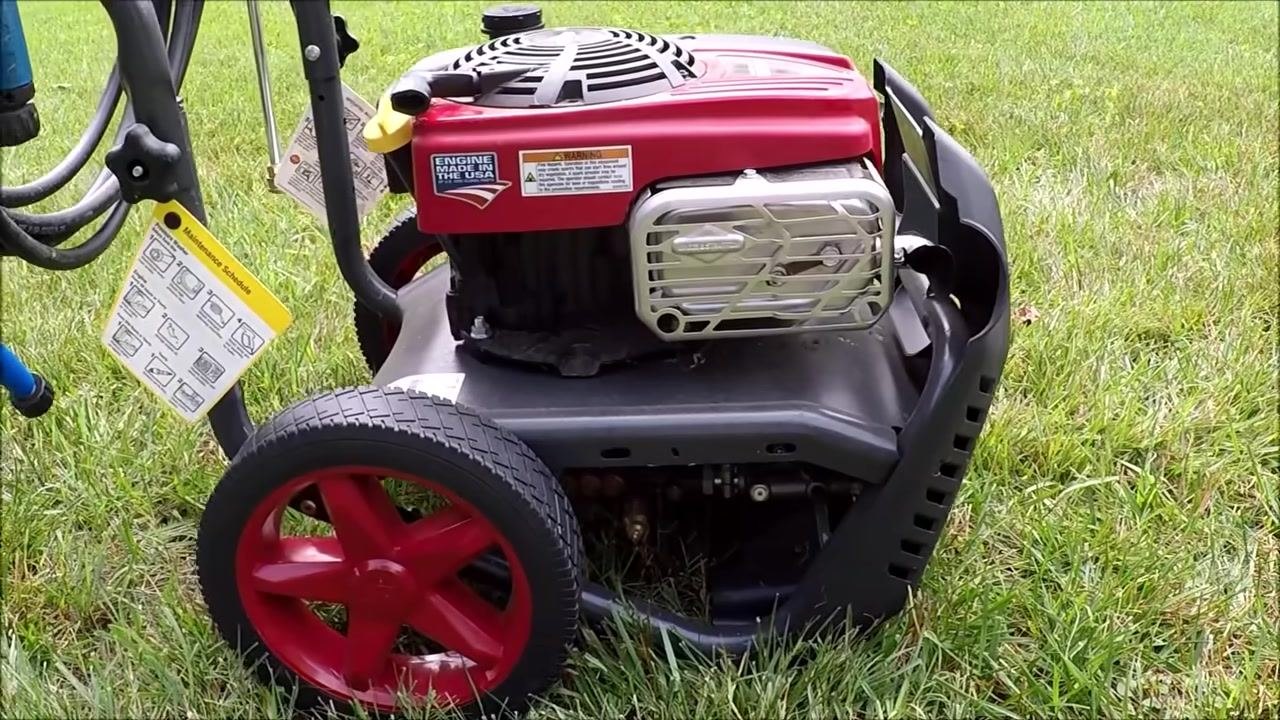
Step 36: View the unit from above to confirm assembly
Check that the engine cover is properly fastened and the oil and fuel caps are tightly closed. Ensure the air intake and exhaust areas are unobstructed and free of debris.
Step 37: Examine the entire unit for completeness
Verify that the hose, spray gun, and all accessories are attached to the frame, inspect the wheels for stability and proper attachment, and confirm that all tags and labels are present and readable.
Step 38: Check rear connections and hose storage
Inspect the rear of the power washer for hose connections and storage hooks, and ensure the hose is neatly coiled and secured. Confirm the "POWERflow+" branding and all connection ports are visible and accessible.
Step 39: Review the engine and exhaust area for safety
Examine the engine's exhaust shield and surrounding area for signs of wear or damage. Confirm the "Engine Made in the USA" label and warning stickers are intact, and check that the maintenance schedule tag is attached to the handle.
Step 40: Perform a final visual check
Ensure all components, including the hose, handle, and wheels, are properly assembled, and confirm the maintenance schedule tag is visible and accessible for future reference.
Step 41: Complete the inspection with a top-down overview
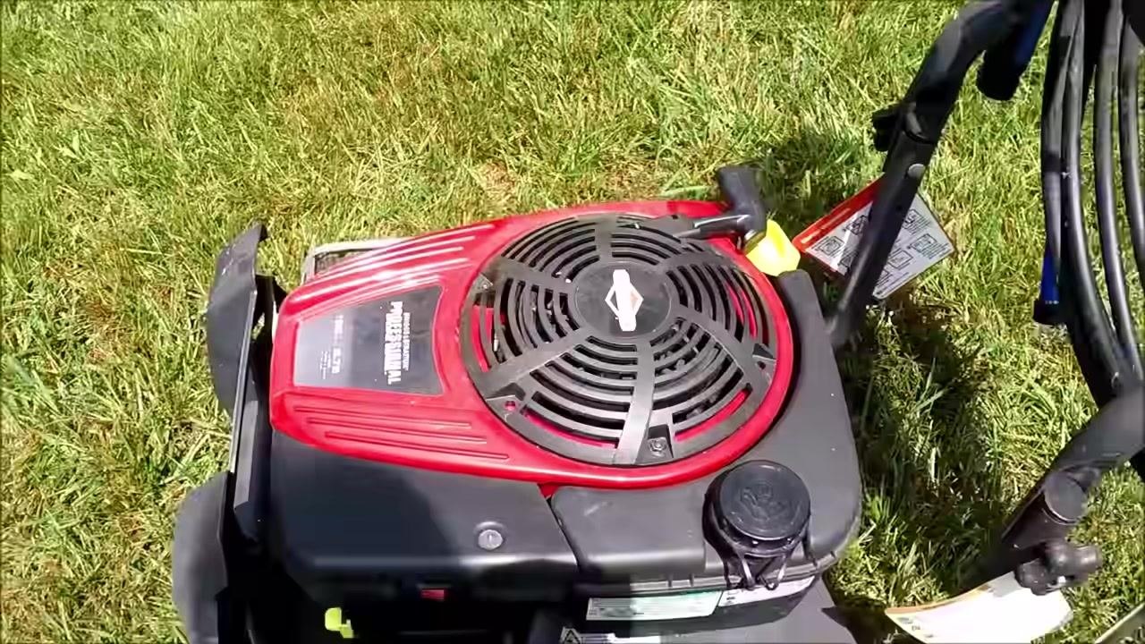
Take a final look at the engine cover, confirming the "Briggs & Stratton Professional" branding and model information (190cc, 875 Series). Ensure the pull handle and all controls are in their default positions.
Verification and summary
By completing this procedure, you have inspected the PowerFlow Plus pressure washer, confirmed the starting issue was caused by a carburetor blockage, removed and disassembled the carburetor, cleaned its float bowl, jet, and internal passages, reassembled it with the float and needle correctly seated, and reinstalled it on the engine with all linkages and fuel connections intact. You have also confirmed that the engine starts, runs smoothly, and shows no leaks, loose parts, or abnormal sounds, and that all safety labels, caps, and accessories are properly in place. The power washer is now fully inspected and ready for use or storage.
What's next
With the carburetor cleaned and the engine confirmed to run smoothly, the pressure washer is ready for normal operation. Refer to the maintenance schedule tag attached to the handle for future service intervals, and continue to monitor the air filter condition, since a greasy or oily filter can contribute to the same type of fuel delivery issues addressed in this procedure.
Generation details: cost, quality tiers
Docsie billed 6,000 credits ($4.20) to analyze this 12-minute video at standard quality. The rewrite, template fill and Word/PDF exports were included. The same video at each quality tier:
| Quality | Frames sampled | Credits | Approx. cost |
|---|---|---|---|
| Draft | every 16-30 s | 3,000 | $2.10 |
| Standard (this guide) | every 8-15 s | 6,000 | $4.20 |
| Detailed | every 4-7 s | 12,000 | $8.40 |
| Ultra | every 1-3 s | 24,000 | $16.80 |
Credits priced at $0.70 per 1,000; plans include a monthly allowance. Enterprise customers on on-premise or bring-your-own-model deployments run this on their own inference and pay no per-video credits.
Generated by Docsie Video-to-Docs on 2026-09-28 from a 11-minute video. Screenshots are frames from the source video and belong to their creator, mountainbikekayak, whose original is embedded above. If you own this video and want the guide removed or credited differently, contact us and we will act within one business day.