
How to Use a Torque Angle Gauge
This documentation explains how to use a torque angle gauge, specifically the OTC 4554 Torque Angle Gauge, for measuring torque angle during bolt tightening procedures. It walks through unboxing the tool, reviewing its construction, and applying it correctly—both in open work areas and confined engine bays—to achieve accurate torque angle specifications.
Video: OTC 4554 Torque Angle Gauge Unboxing, Overview, Usage and Demo by DrShock (2022). All credit for the demonstration goes to the creator; watch the original on YouTube. The written guide below was generated from this video by Docsie. Creator? Request a change or removal.
This documentation explains how to use a torque angle gauge, specifically the OTC 4554 Torque Angle Gauge, for measuring torque angle during bolt tightening procedures. It walks through unboxing the tool, reviewing its construction, and applying it correctly—both in open work areas and confined engine bays—to achieve accurate torque angle specifications.
Purpose
This procedure describes how to unbox, set up, and use the OTC 4554 Torque Angle Gauge to measure the rotational angle applied to a fastener after it has been torqued to an initial value. Following these steps ensures accurate and safe fastener installation during automotive or mechanical repairs.
Scope
This procedure applies to any bolt-tightening task that specifies a torque value followed by an additional angle of rotation, including work performed in tight engine compartments where clearance is limited.
Required equipment and PPE
- OTC 4554 Torque Angle Gauge (gauge and retaining bar)
- Torque wrench
- Eye protection meeting ANSI Z87.1 and OSHA standards
- Gloves
Step-by-step procedure
Unbox the OTC 4554 torque angle gauge
Identify the product before use: the OTC 4554 Torque Angle Gauge is designed for measuring torque angle during bolt tightening. The tool is made in Taiwan.
Inspect the packaging for safety information
Check the back of the package for warnings and instructions, which are printed in multiple languages. Wear eye protection that meets ANSI Z87.1 and OSHA standards before proceeding.

Remove the gauge and retaining bar
Take the gauge and the retaining bar out of the packaging. These two components are the primary items included with the tool.
Examine the gauge face and drive
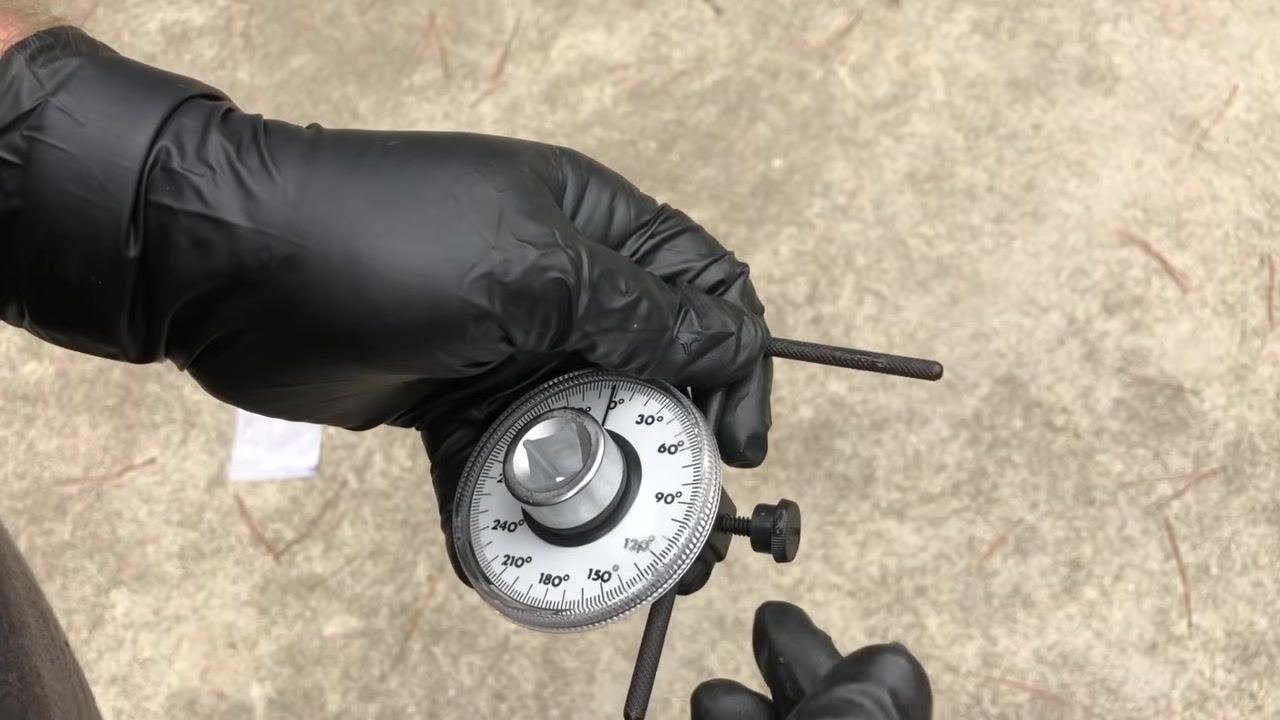
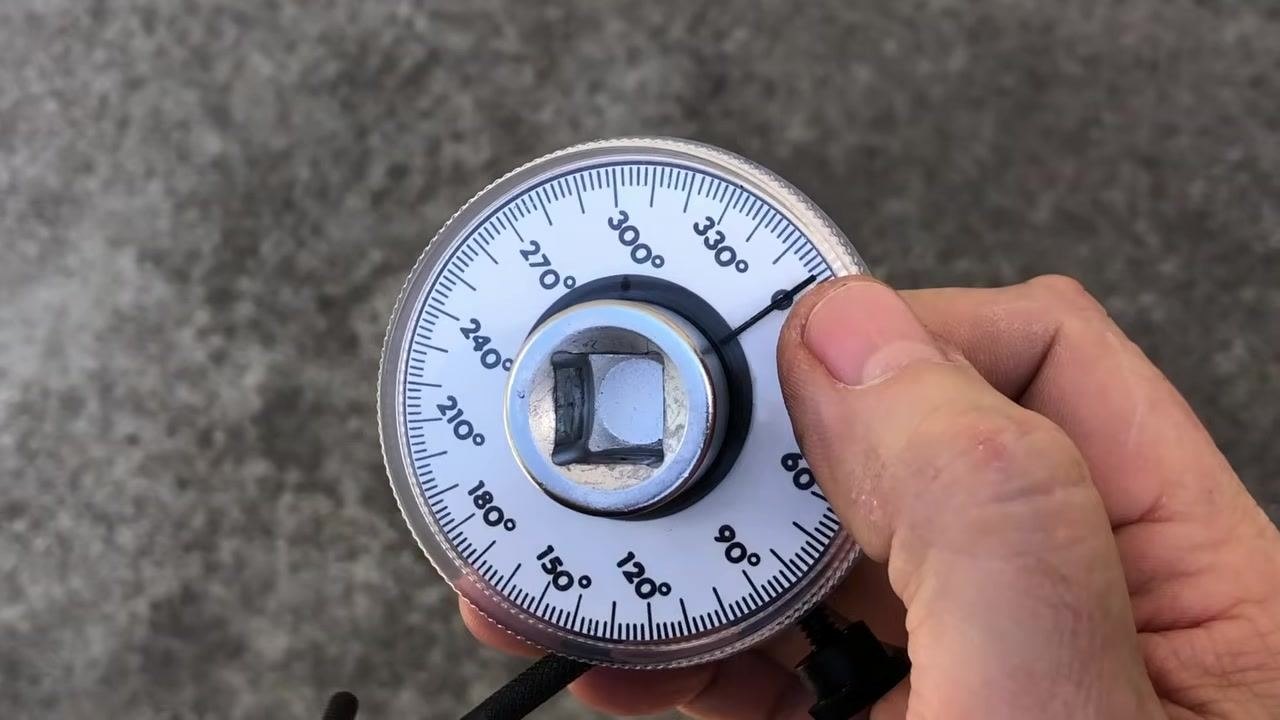
Look closely at the gauge: it features a 360-degree scale marked in 2-degree increments, with larger marks at every 10 degrees. The center has a half-inch square drive for attachment, and the retaining bar stabilizes the gauge during use.
Attach the retaining bar
Insert the retaining bar into the gauge. The bar braces the gauge against a fixed point—such as another bolt or an engine part—to prevent rotation during measurement.
Review the gauge's construction
Note that the gauge is built from plastic and metal, with a snap ring holding the assembly together. A thumb screw secures the retaining bar in place, and the model number "4554" is visible on the gauge face.
Zero the gauge before use
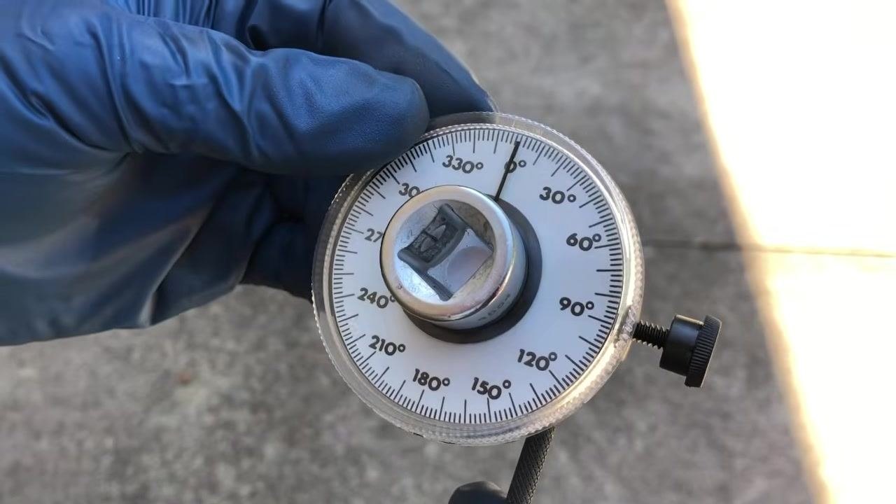
Hold the gauge and rotate the face to align the pointer with zero degrees. Ensure the retaining bar is braced against a fixed object so the gauge cannot move during tightening.
Use the torque angle gauge to measure rotation
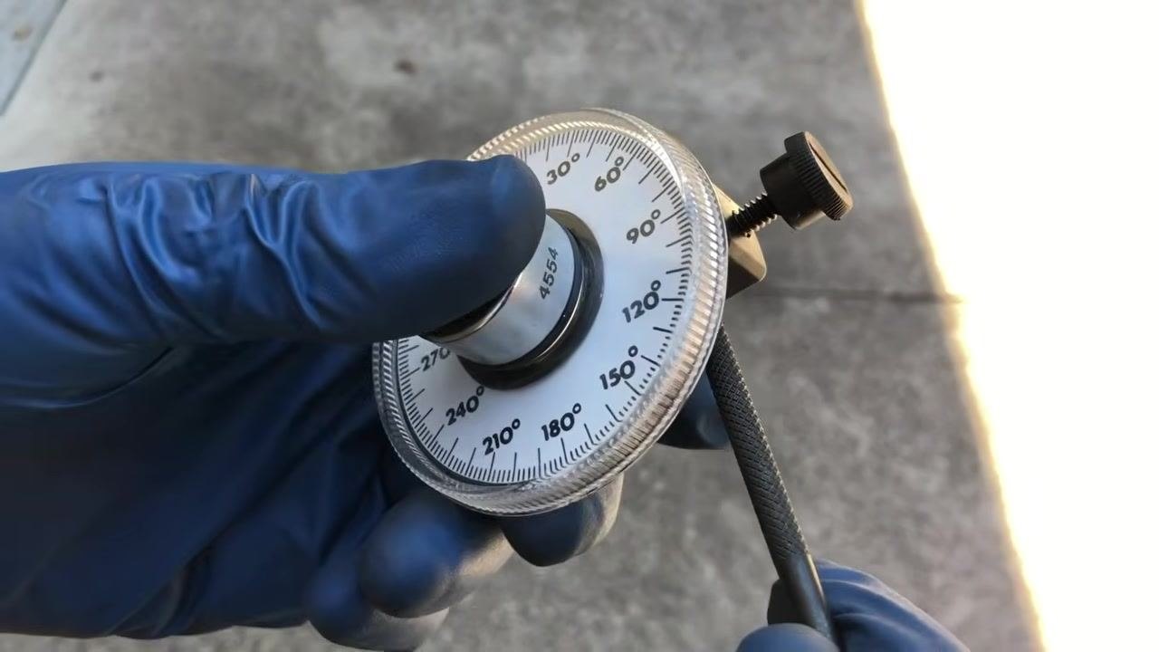
After tightening the bolt to the specified torque (for example, 40 ft-lbs), attach the gauge to the torque wrench. Turn the wrench until the pointer reaches the desired angle (for example, 60 degrees); the gauge indicates the angle turned from the zero position.
Remove the gauge after use
Loosen the thumb screw and detach the retaining bar if needed. The tool is designed for easy attachment and removal.
Applying the gauge in confined spaces
Prepare a confined work area
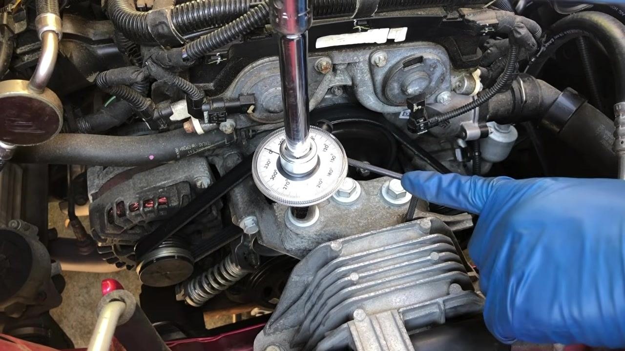
Confirm you have enough clearance to use the torque angle gauge, even in tight engine compartments. Verify that the bolts to be tightened have already been torqued to the initial value (for example, 37 foot-pounds), and wear gloves and eye protection.
Attach the gauge to the fastener
Insert the gauge between the torque wrench and the socket on the bolt. Secure the retaining bar against a fixed engine bracket or component to prevent the gauge from rotating during use.
Set the gauge to zero on the fastener
Rotate the gauge face so the pointer aligns with the zero-degree mark. Double-check that the retaining bar remains firmly braced against a stationary part.
Tighten the fastener to the specified angle
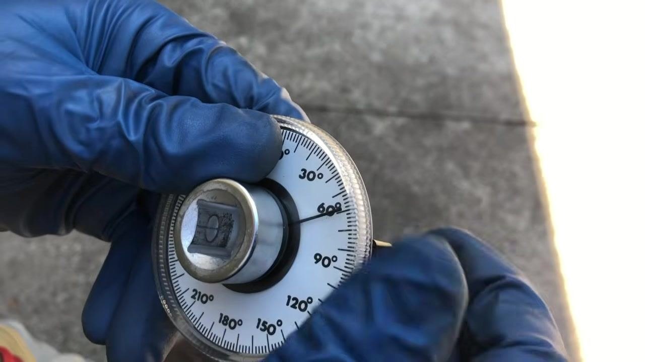
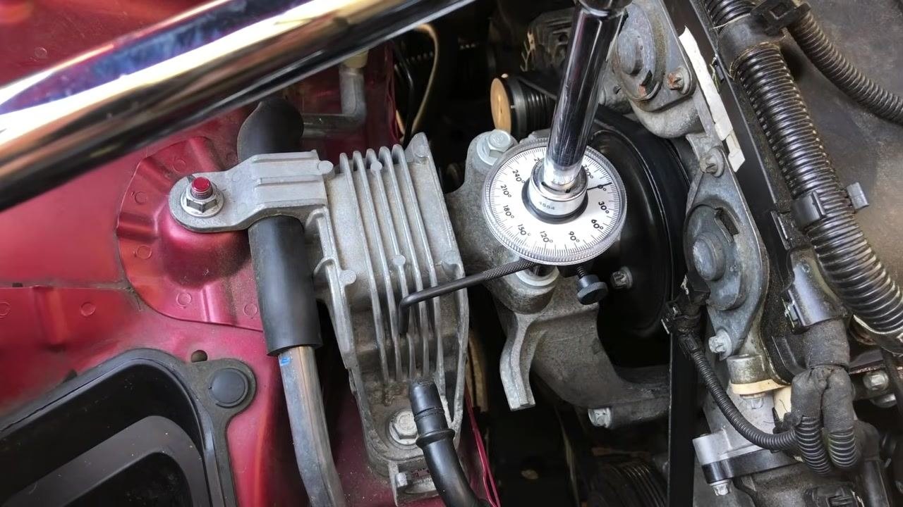
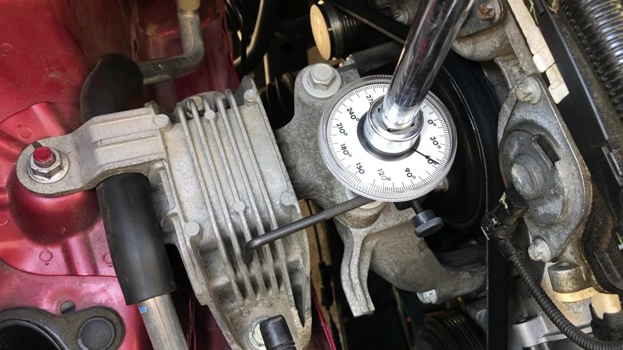
Slowly turn the torque wrench while observing the gauge, continuing until the pointer reaches the required angle (for example, 60 degrees). In this example, the retaining bar remains braced against a bracket as the gauge is turned exactly 60 degrees.
Verify the achieved torque angle
Stop turning once the pointer reaches the desired angle (for example, 60 degrees). Visually confirm the gauge reading to ensure accuracy.
Remove the gauge and inspect the fastener
Detach the torque angle gauge from the fastener and inspect the bolt and surrounding area to confirm proper installation.
Interpret torque specifications with angle ranges
Be aware that manuals may list torque specifications in Newton meters (Nm) or foot-pounds (ft-lbs), followed by an additional angle range (for example, 60–70 degrees). Any value within the specified range is acceptable to complete the torque procedure.
Repeat the procedure for additional fasteners
For each bolt, set the gauge to zero, brace the retaining bar, and turn to the specified angle. In this demonstration, the gauge is set precisely to 60 degrees, the minimum required angle.
Tool review and support
Compare construction and alternative tools
The OTC 4554 torque angle gauge has a simple construction with few parts that could fail. It was selected for this review for its perceived higher quality, though similar tools are available from other brands.
Consider purchasing options
Use the information provided in this guide to make an informed decision about which torque angle gauge best suits your needs, whether the OTC model or a comparable alternative.
Seek assistance if needed
If you have questions about using the OTC 4554 Torque Angle Gauge or about torque angle procedures in general, direct your questions to the appropriate support channel for clarification.
Review the gauge's key features
Take a final look at the OTC 4554 Torque Angle Gauge: note the clear degree markings (0° to 360°), the central square drive, and the pointer used for precise angle measurement. The tool is compact and easy to handle.
Verification and summary
Confirm the following before considering the torque angle procedure complete:
- The bolt was torqued to its initial specified value before the angle measurement began.
- The gauge was zeroed and the retaining bar was braced against a fixed point before tightening.
- The pointer reached the specified angle (or fell within the specified angle range) before tightening stopped.
- The gauge was removed and the fastener and surrounding area were inspected.
Always consult your vehicle or equipment manual for the correct torque and angle values. By following this procedure, you can confidently use the OTC 4554 Torque Angle Gauge—or a comparable torque angle gauge—for precise torque angle applications, including in confined spaces.
Generation details: cost, quality tiers
Docsie billed 2,000 credits ($1.40) to analyze this 4-minute video at standard quality. The rewrite, template fill and Word/PDF exports were included. The same video at each quality tier:
| Quality | Frames sampled | Credits | Approx. cost |
|---|---|---|---|
| Draft | every 16-30 s | 1,000 | $0.70 |
| Standard (this guide) | every 8-15 s | 2,000 | $1.40 |
| Detailed | every 4-7 s | 4,000 | $2.80 |
| Ultra | every 1-3 s | 8,000 | $5.60 |
Credits priced at $0.70 per 1,000; plans include a monthly allowance. Enterprise customers on on-premise or bring-your-own-model deployments run this on their own inference and pay no per-video credits.
Generated by Docsie Video-to-Docs on 2026-09-20 from a 3-minute video. Screenshots are frames from the source video and belong to their creator, DrShock, whose original is embedded above. If you own this video and want the guide removed or credited differently, contact us and we will act within one business day.