
How to Sharpen Lathe Tools
This SOP explains how to sharpen lathe tools by grinding a high-speed steel (HSS) tool bit blank on a bench grinder for use on a manual lathe. It is intended for students, beginners, and anyone new to manual lathes who has purchased a used machine and needs to prepare cutting tools correctly. Following these steps ensures the tool bit has the proper relief angles and edge geometry for effective, chatter-free cutting.
Video: How To Grind an HSS Lathe Tool Bit by Practical Machinist (2021). All credit for the demonstration goes to the creator; watch the original on YouTube. The written guide below was generated from this video by Docsie. Creator? Request a change or removal.
This SOP explains how to sharpen lathe tools by grinding a high-speed steel (HSS) tool bit blank on a bench grinder for use on a manual lathe. It is intended for students, beginners, and anyone new to manual lathes who has purchased a used machine and needs to prepare cutting tools correctly. Following these steps ensures the tool bit has the proper relief angles and edge geometry for effective, chatter-free cutting.
Purpose
Many new machinists or shop owners purchase used manual lathes without knowing how to grind tool bits correctly. Factory edges on HSS tool bit blanks are not suitable for cutting and must be ground before use. An improperly ground tool — or one used straight from the factory without grinding — can cause vibration, chatter, and poor cutting performance. Proper relief angles are essential both for effective cutting and for tool longevity.
Scope
This procedure covers grinding an HSS tool bit blank for use on a manual lathe, including side clearance, front clearance, edge shaping, inspection, and a test cut to confirm the ground tool performs correctly. It does not cover CNC tooling or carbide insert tooling.
Required equipment and PPE
- High-speed steel (HSS) tool bit blank
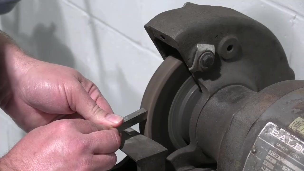
- Bench grinder (a Baldor grinder is used in this procedure)
- Water or coolant for cooling the tool bit between grinding passes
- Cutting fluid for use during the test cut
- Tool holder and manual lathe with chuck and digital readout
- Scribe or pointer for identifying the cutting edge
- Safety glasses (required at all times when operating the bench grinder or lathe)
Safety note: Always wear safety glasses when operating a bench grinder or lathe. Keep the work area clear of obstructions and make sure the grinder's tool rest is properly adjusted before you begin.
Procedure
Preparing to grind the tool bit
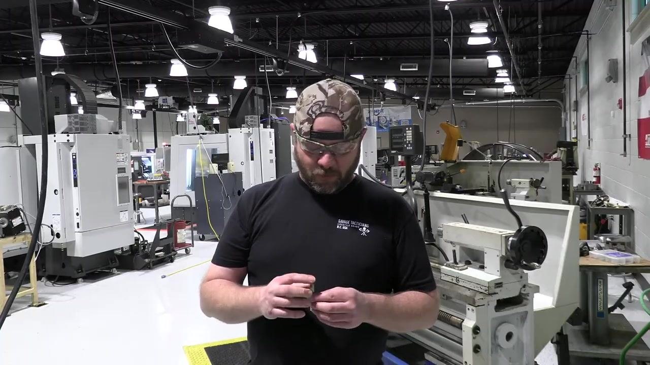
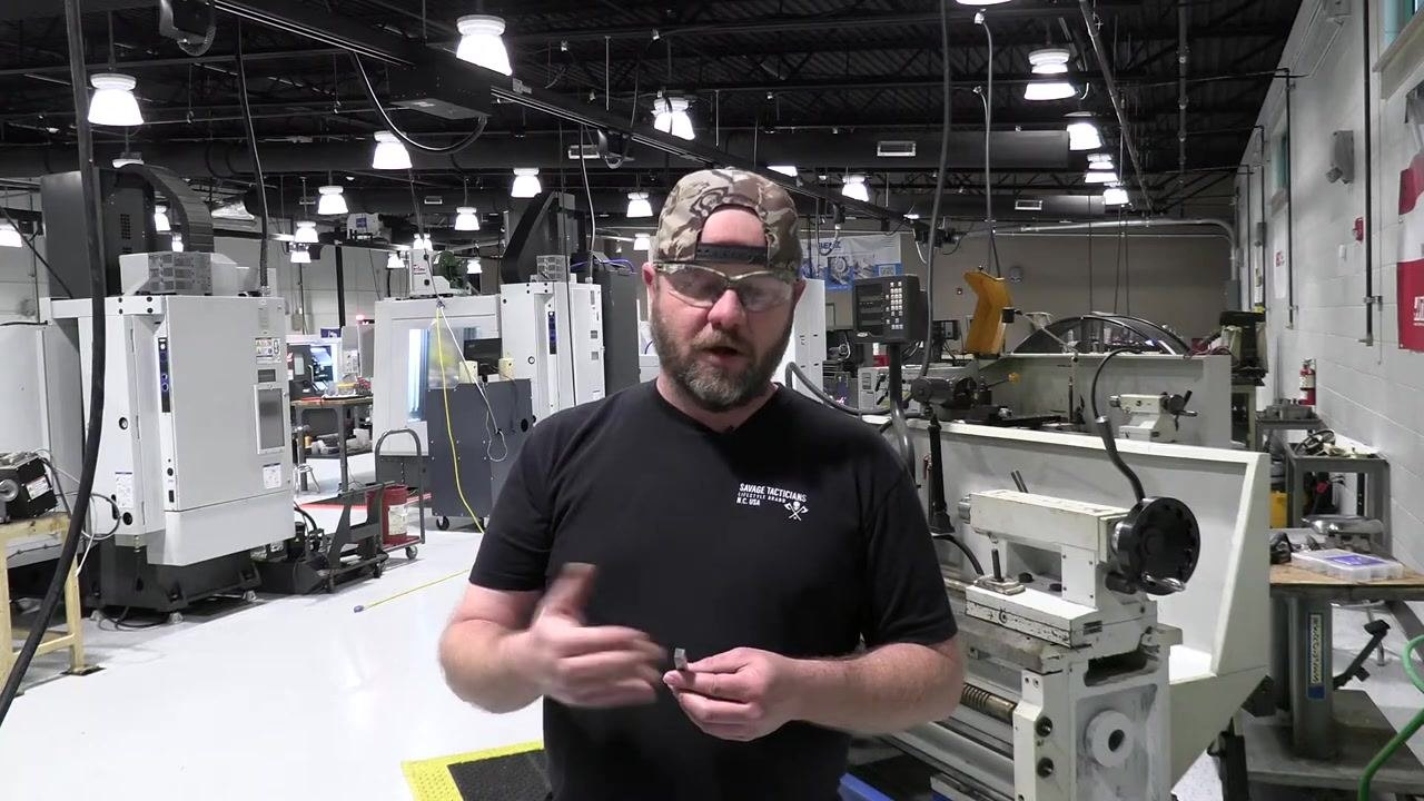
Step 1: Approach the grinding station. Bring the HSS tool bit blank to the bench grinder and hold it ready for the first grinding pass.
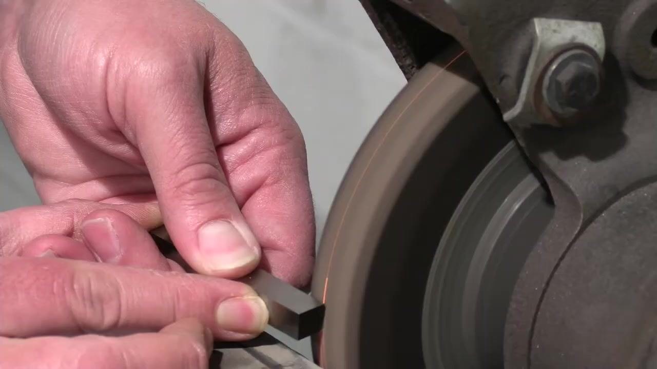
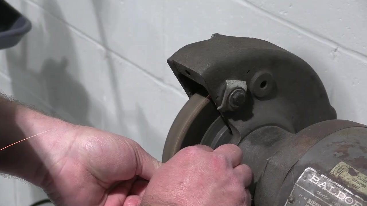
Step 2: Position the tool bit at the grinder. Grind approximately a 15-degree angle on one side of the tool bit's face and approximately a 30-degree angle on the other side. Precision is not critical, but the angles should be close to these values for effective cutting. Avoid overheating the tool bit, as excessive heat can damage the steel. Do not grind the tip excessively sharp or blunt — aim for a balanced tip with adequate clearance, since too much clearance weakens the tool and too little hinders cutting performance.
Grinding the side clearance
Step 3: Inspect the tool bit for an existing slant. Examine the HSS tool bit and identify if one side already has a slant. Plan to use this slanted side to your advantage when creating the side clearance.
Step 4: Prepare to grind the side clearance. Hold the tool bit so the slanted side will be cleaned up and refined. The goal is a side clearance angle that rakes down from the top to the bottom of the tool bit. Position the bottom of the tool bit against the grinding wheel and leave about a fingernail-thickness gap between the top of the tool bit and the wheel.
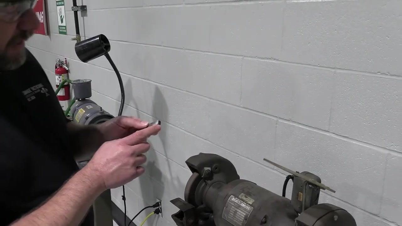
Step 5: Grind the side clearance. Gently press the bottom of the tool bit into the wheel while maintaining the gap at the top. Let the grinding wheel work its way up toward the top edge of the tool bit. Keep the tool bit flat against the tool rest — do not roll or tilt it into the wheel.
Step 6: Monitor the grinding process. Periodically check the gap and the progress of the grind. Avoid overheating the tool bit, since excessive heat can anneal the steel and ruin its hardness.
Safety note: If the tool bit becomes too hot to touch, remove it from the wheel immediately and cool it in water or coolant.
Step 7: Cool the tool bit as needed. Remove the tool bit from the grinding wheel to cool it before it gets too hot. This step is critical to preserve the hardness of the HSS tool bit.
Step 8: Resume grinding to complete the side clearance. After cooling, return the tool bit to the same position and continue grinding. Let the wheel do the work while maintaining the same angle and gap.
Step 9: Inspect the ground surface. Check that the slant on the tool bit is forming correctly, with one point sticking out further than the other. This geometry is necessary for effective cutting action on the lathe.
Step 10: Make final passes as needed. If the side clearance is nearly complete, make one more light grinding pass to finish the surface, then cool the tool bit again.
Grinding the front clearance
Step 11: Inspect the ground surface for uniformity. Hold the tool bit under a light source and examine the reflection on the ground surface. You should see a single, smooth reflection; different shades of gray indicate multiple flats or angles, which is undesirable. Aim for one continuous, even surface for optimal cutting performance.
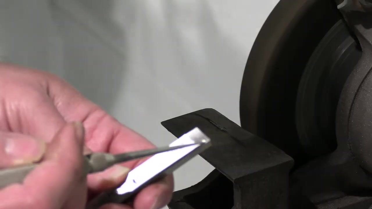
Step 12: Prepare to grind the front clearance. Identify the area on the tool bit that needs to be cleaned up. Use the same technique as before: place the bottom of the tool bit against the grinding wheel, leaving a gap at the top, and let the wheel gradually work its way up to create a smooth front clearance angle.
Step 13: Begin grinding the front clearance. Position the bottom of the tool bit against the grinding wheel, maintaining a visible gap at the top. Move slowly and steadily, and avoid pushing the tool bit into the wheel — let the wheel do the work to prevent creating a curved surface that matches the wheel's profile.
Step 14: Monitor heat buildup and cool as needed. Watch for excessive heat buildup as you grind. Grinding the front clearance can take longer than the side clearance and may require several cooling cycles.
Safety note: If the tool bit becomes too hot to touch, remove it from the wheel and cool it in water or coolant before continuing.
Step 15: Maintain a steady, patient approach. Continue grinding with a gentle touch, without allowing the tool bit to overheat. Do not rush the process; patience is key to achieving a flat, even surface. Let the wheel gradually work its way up the tool bit while maintaining the correct angle and gap.
Step 16: Continue grinding until the front clearance is complete. Repeat the grinding and cooling cycle as necessary. Keep the surface flat and the angle consistent — pushing too hard results in an incorrect profile.
Step 17: Finalize the front clearance. Make final passes as needed, checking each time for a single, smooth reflection on the ground surface. Confirm the front clearance is flat and even, with no multiple shades or flats.
Step 18: Let the wheel finish the work. Allow the grinding wheel to finish working its way up the tool bit without applying excessive pressure. Maintain a consistent angle and gap until the desired front clearance is achieved.
Step 19: Avoid creating a curved surface that matches the wheel's profile. Hold the tool bit steadily against the grinding wheel and do not let the wheel shape the tool bit into a concave or curved surface. Maintain a flat contact area by letting the wheel gradually work its way up the tool bit rather than pressing the tool bit into the wheel. The goal is to avoid a "mirror image" of the wheel's curvature on the tool bit, which would create incorrect cutting geometry.
Continue to check your progress frequently and make adjustments as needed to maintain a flat, even surface on both the side and front clearances.
Shaping the top edge and straight face
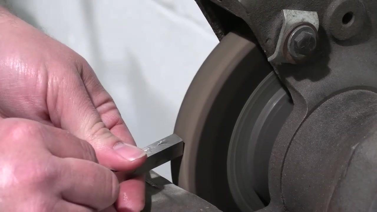
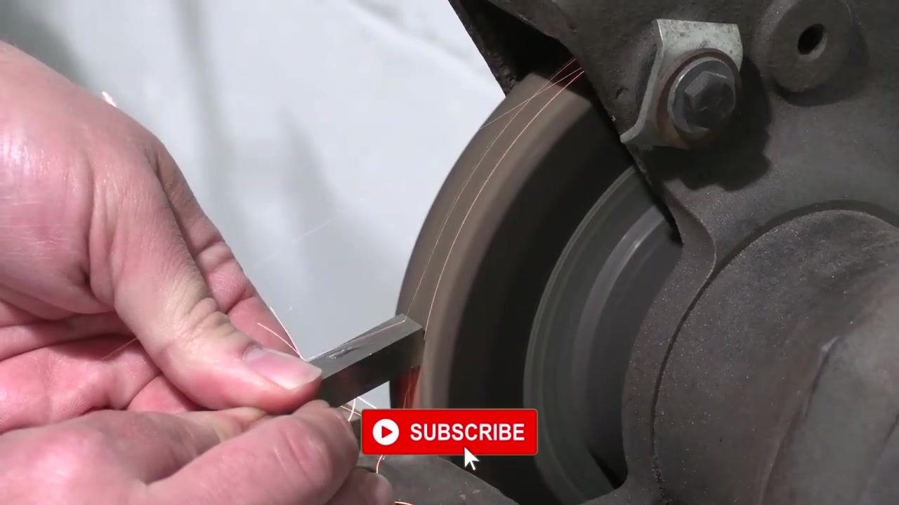
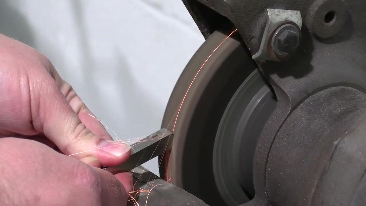
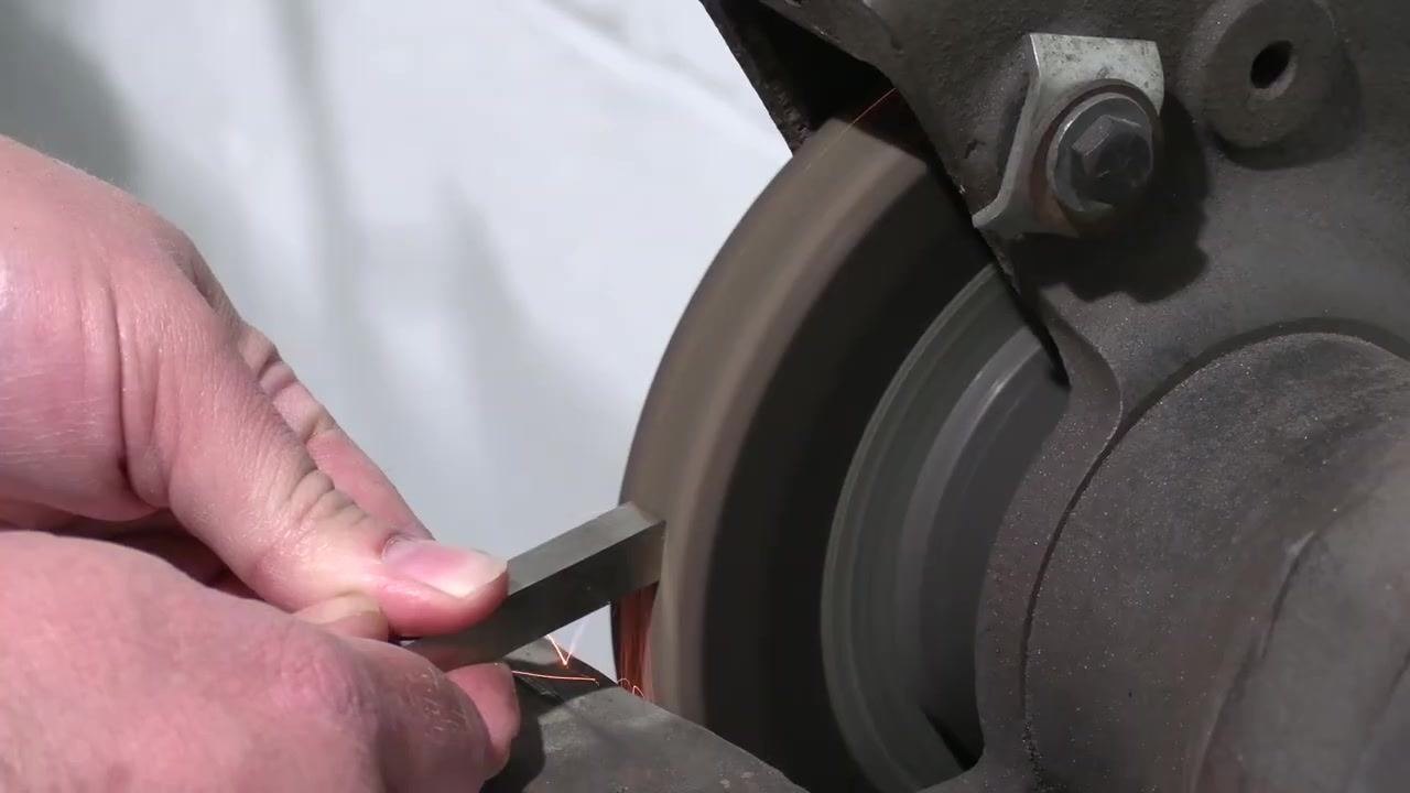
Step 20: Position the tool bit against the grinding wheel. Hold the tool bit firmly with both hands and place it at the desired angle against the rotating grinding wheel. Keep your fingers clear of the wheel and maintain a steady grip. Watch for the initial contact point where sparks begin to appear.
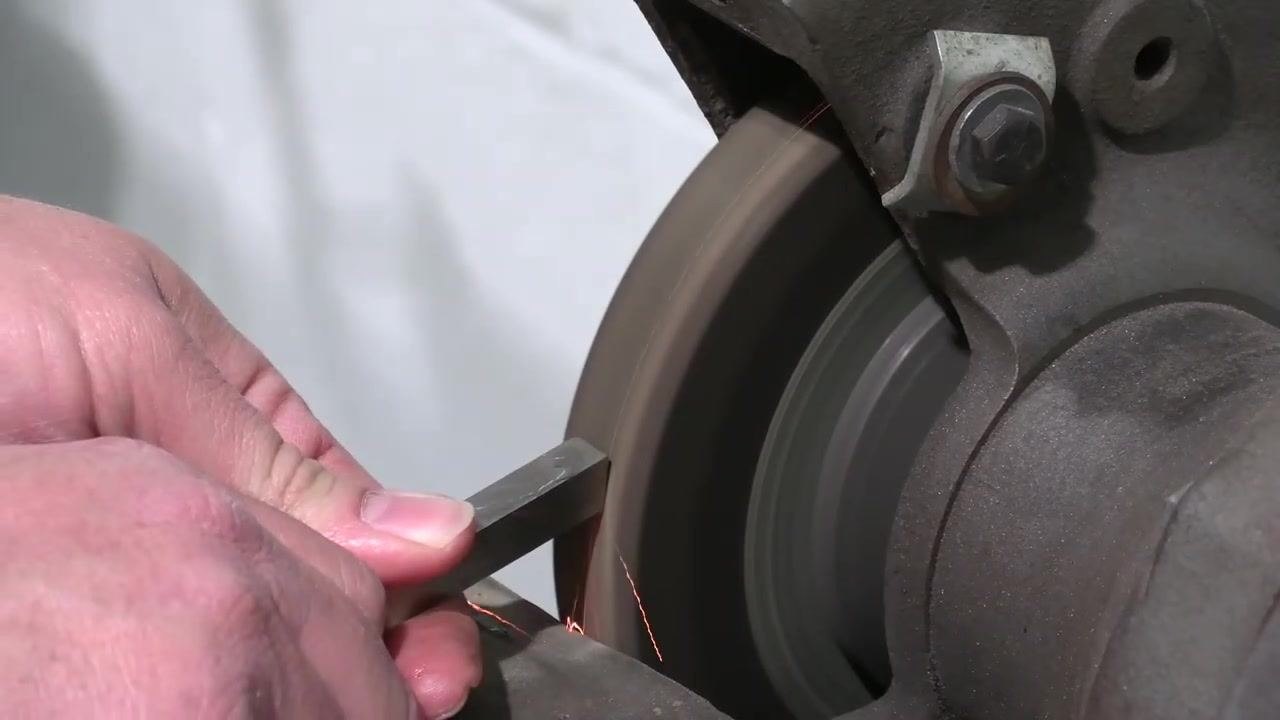
Step 21: Begin grinding the clearance angle. Gently press the tool bit against the wheel, allowing it to remove material. Maintain a consistent angle and pressure, and gradually move the tool bit upward as you grind — let the wheel do the work and work its way up.
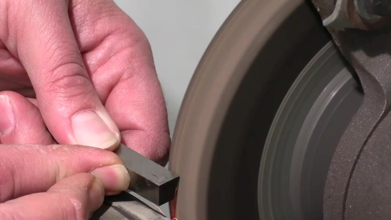
Step 22: Continue grinding until the desired clearance is achieved. Periodically check the tool bit to confirm you are achieving the correct clearance. Do not force the tool; let the wheel do the work, moving it smoothly along the wheel until the necessary clearance is present.
Step 23: Inspect the tool bit for proper clearance. Remove the tool bit from the wheel and visually inspect the ground surface. Confirm the clearance angle is present and that the point sticks out further, and identify any remaining straight edges that need further work.
Step 24: Prepare to grind the straight edge. Hold the tool bit in front of the wheel, ready to address the straight edge. Do not focus on the finish at this stage, since more material still needs to be removed along this edge.
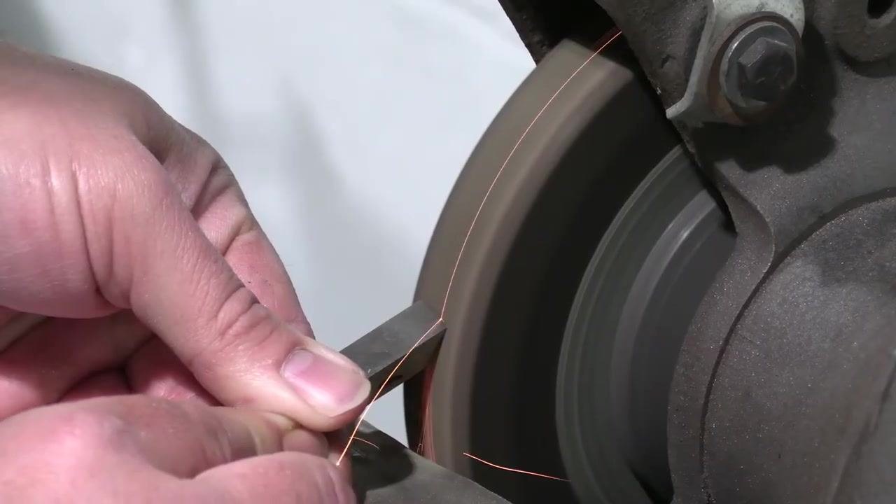
Step 25: Grind the straight edge with proper technique. Hold the tool bit down and over while grinding. Position it at the correct angle against the wheel and begin grinding with steady pressure and movement.
Step 26: Continue grinding until the edge is shaped. Maintain the down-and-over position while grinding. Watch the flow of sparks and the gradual shaping of the edge, and continue until the straight edge is properly formed and excess material is removed.
Finalizing the tool bit and preparing for a test cut
Step 27: Continue shaping the tool bit edge. Hold the tool bit firmly with both hands, maintaining the correct angle against the grinding wheel. Gently press the tool bit to the wheel and focus on refining the edge, ensuring smooth and even removal of material.
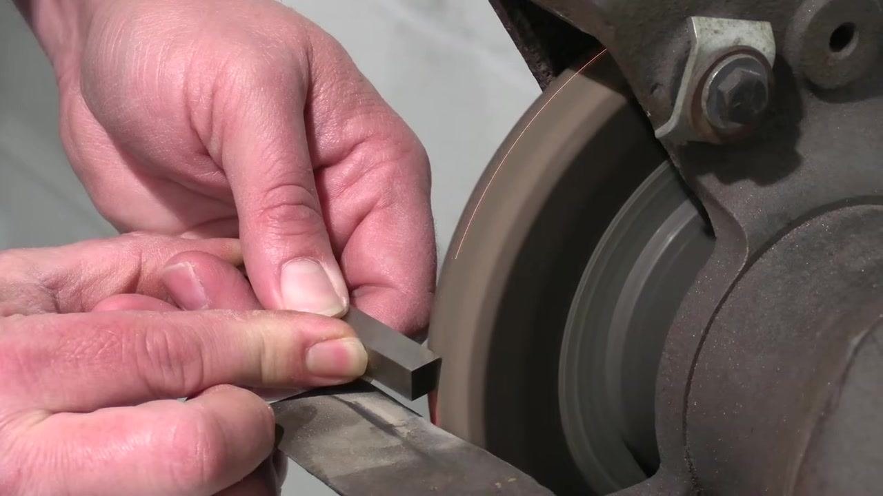
Step 28: Maintain consistent grinding technique. Keep the tool bit steady and continue grinding along the edge. Watch the flow of sparks as you shape the tool bit, and ensure it remains at the intended angle for uniform results.
Step 29: Check progress and make final adjustments. Periodically pause to inspect the tool bit's edge. Make any necessary adjustments by lightly grinding areas that require further shaping, and continue until the edge is sharp and the desired profile is achieved.
Step 30: Inspect the finished tool bit. Remove the tool bit from the grinder and visually inspect the ground surfaces. Confirm that the point of the tool bit now sticks out further than any other point, and ensure the clearance and edge geometry are correct.
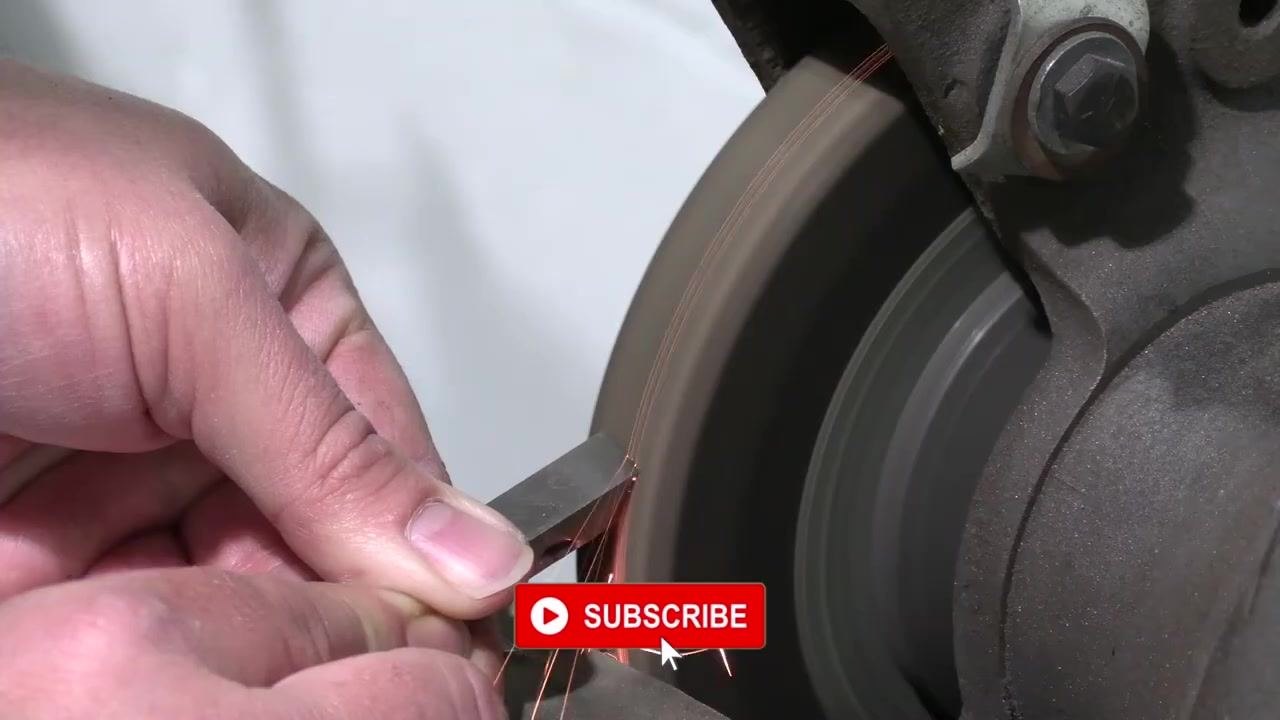
Step 31: Review the tool bit's angles and slants. While inspecting, note the slanting angles: the top is slanted back and the sides are slanted down. Rotate the tool bit in your hands to check all faces and ensure the geometry matches the intended design.
Step 32: Prepare for a test cut. Hold the finished tool bit in both hands, ready to perform a test cut. Position it near the grinder for a final check before moving to the cutting operation, and ensure it is cool and free of burrs or rough edges.
Step 33: Perform a final inspection before the test cut. Double-check the tool bit's cutting edge and overall shape to confirm it is ready for use in a test cut.
Safety note: Always allow the tool bit to cool before handling it after grinding. Use a brush or cloth to remove any debris, and wear safety glasses throughout the process.
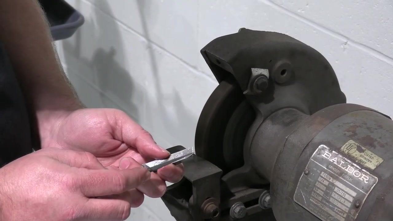
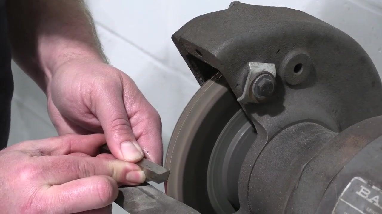
Performing the test cut and managing heat
Step 34: Make a final grinding pass if needed. Hold the tool bit with both hands and position it against the spinning grinding wheel. Carefully grind the edge, focusing on final shaping, and watch the contact point for any signs of overheating such as discoloration or excessive sparks.
Step 35: Monitor for overheating. This stage is where the tool bit is most likely to overheat. Use light, controlled pressure to minimize heat buildup, and pause to let the tool bit cool if it becomes too hot.
Step 36: Complete the grinding process. Continue grinding as needed, maintaining a steady hand and watching for sparks, until the tool bit edge is sharp and the geometry is correct.
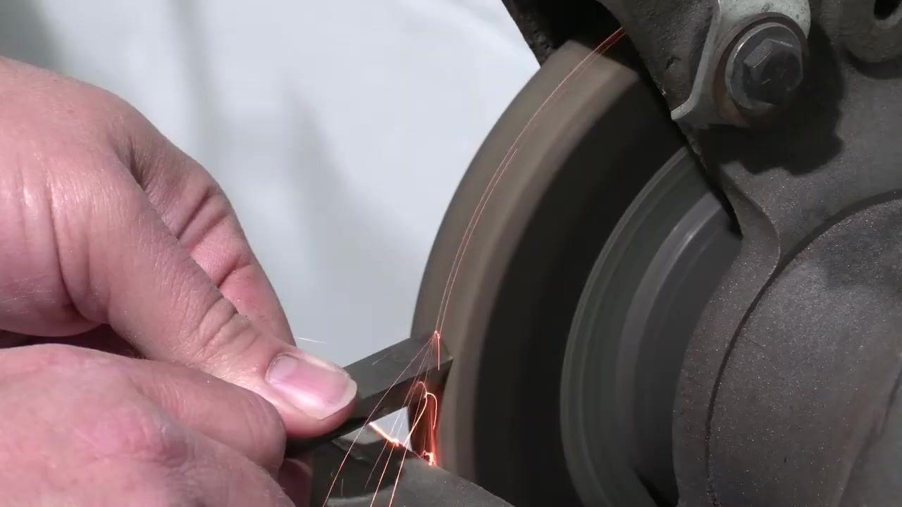
Step 37: Insert the tool bit into the tool holder. Remove the finished tool bit from the grinder, align it with the tool holder, and insert it into the holder.
Step 38: Identify the tool orientation. Confirm the tool bit's orientation — in this case, a left-hand tool, right-hand tool, which cuts to the left. Use a scribe or pointer to indicate the cutting edge and its direction.
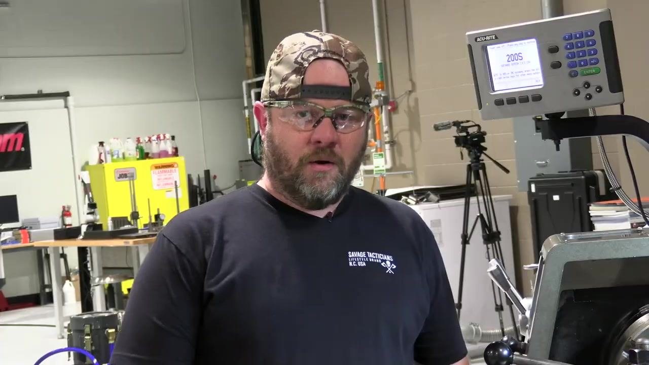
Step 39: Prepare for heat management during cutting. High-speed steel is sensitive to heat, and excessive heat can damage the tool during cutting. Prepare to apply cutting fluid to the tool bit to help control temperature during the cut.
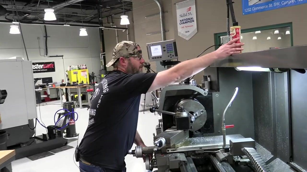
Step 40: Apply cutting fluid. Reach for a can of cutting fluid stored above the lathe and prepare to apply a small amount to the end of the tool bit.
Step 41: Turn on the lathe and prepare for touch-off. Do not flood the tool bit with cutting fluid — a small amount is sufficient. Turn on the lathe using the control panel and prepare to touch off the tool bit against the workpiece to begin the test cut.
Step 42: Observe the spinning workpiece. Watch the workpiece as it spins in the lathe chuck and ensure the tool bit is properly aligned and ready for the test cut.
Step 43: Double-check alignment and readiness. Confirm the tool bit is securely held and properly aligned with the workpiece, and ensure all safety measures are in place before proceeding with the test cut.
Safety note: Always wear safety glasses and use cutting fluid to manage heat when working with high-speed steel tool bits. Do not rush the process — allow the tool and workpiece to cool as needed to prevent damage.
Observing chip formation and completing the pass
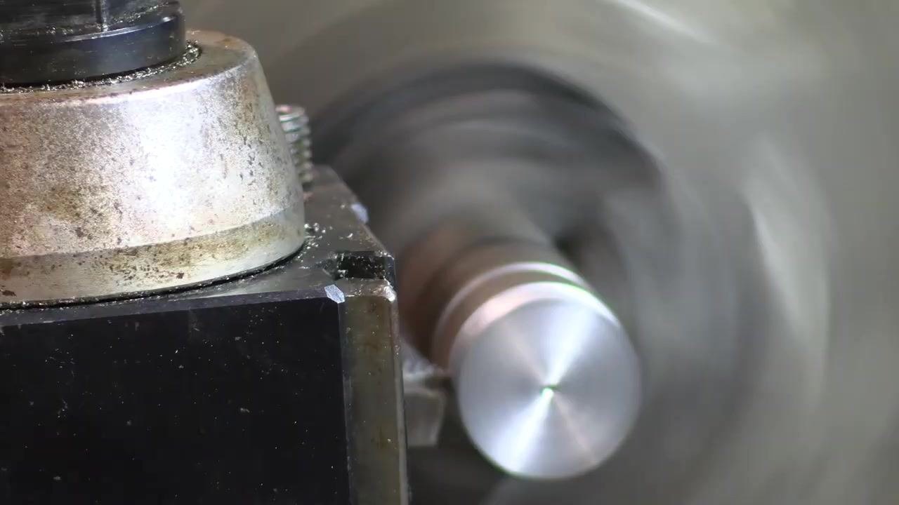
Step 44: Monitor chip formation during machining. Observe the cutting tool and workpiece interface closely. Confirm that metal chips are being produced and ejected from the cutting area, which indicates effective material removal. The presence of chips is a positive sign that the tool is engaging the workpiece correctly.
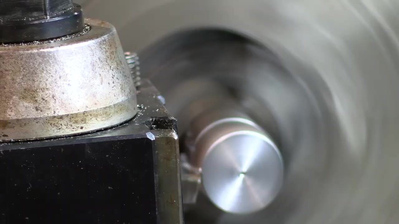
Step 45: Evaluate cutting parameters. Consider the current spindle speed and depth of cut. It may be possible to increase speed and take a heavier cut for more aggressive material removal, but confirm the machine and tooling can handle increased loads before making adjustments.
Step 46: Continue the machining operation. Maintain observation of the cutting process, ensuring chips continue to form and the tool remains engaged with the workpiece. Watch for any changes in chip color, size, or shape, which may indicate tool wear or improper cutting conditions.
Step 47: Prepare for measurement or inspection. As the machining operation nears completion, prepare to measure the workpiece for dimensional accuracy using a micrometer or other measuring tool to check the finished diameter.
Step 48: Complete the machining pass. Allow the tool to finish the current pass along the workpiece, then be ready to stop the machine and inspect the finished surface.
Verification and summary
Once the grinding and test cut are complete, verify the following:
- The side clearance rakes down from the top to the bottom of the tool bit, with one point sticking out further than the other.
- The front clearance shows a single, smooth reflection under a light source, with no multiple shades or flats.
- The straight edge is fully formed with excess material removed.
- The tool bit shows correct top and side slant angles when rotated and inspected by hand.
- The tool bit is cool, free of burrs, and securely seated in the tool holder with the correct orientation identified.
- During the test cut, metal chips are being produced and ejected consistently, confirming the tool is engaging the workpiece correctly.
- The finished workpiece diameter has been checked and confirmed with a micrometer or other measuring tool.
If chatter, vibration, or poor chip formation occurs, recheck the relief angles and clearances and repeat the relevant grinding steps, taking care to cool the tool bit frequently and avoid overheating.
What's next
After confirming the test cut produces clean chips and an acceptable surface finish, you can apply the same grinding method to prepare additional tool bits with different orientations, such as left-hand or right-hand cutting tools, depending on the operations required on your manual lathe.
Generation details: cost, quality tiers
Docsie billed 6,000 credits ($4.20) to analyze this 12-minute video at standard quality. The rewrite, template fill and Word/PDF exports were included. The same video at each quality tier:
| Quality | Frames sampled | Credits | Approx. cost |
|---|---|---|---|
| Draft | every 16-30 s | 3,000 | $2.10 |
| Standard (this guide) | every 8-15 s | 6,000 | $4.20 |
| Detailed | every 4-7 s | 12,000 | $8.40 |
| Ultra | every 1-3 s | 24,000 | $16.80 |
Credits priced at $0.70 per 1,000; plans include a monthly allowance. Enterprise customers on on-premise or bring-your-own-model deployments run this on their own inference and pay no per-video credits.
Generated by Docsie Video-to-Docs on 2026-09-20 from a 11-minute video. Screenshots are frames from the source video and belong to their creator, Practical Machinist, whose original is embedded above. If you own this video and want the guide removed or credited differently, contact us and we will act within one business day.