
How to Create Threads in Creo
This guide shows you how to create threads in Creo Parametric using the Helical Sweep tool. You build a base cylinder, sketch a thread path and axis, define a triangular thread profile, and generate the thread. You then review the result and save the part.
Video: Creo How To Make Threads by Mufasu CAD (2023). All credit for the demonstration goes to the creator; watch the original on YouTube. The written guide below was generated from this video by Docsie. Creator? Request a change or removal.
This guide shows you how to create threads in Creo Parametric using the Helical Sweep tool. You build a base cylinder, sketch a thread path and axis, define a triangular thread profile, and generate the thread. You then review the result and save the part.
Prerequisites
- PTC Creo installed and ready to use
- Familiarity with the Model tab and basic sketching tools
Start a new part and create a base cylinder
Step 1: Start a new part and prepare the workspace
Open PTC Creo and start a new part file. Take a moment to get familiar with the workspace, and make sure you are in the Model tab.
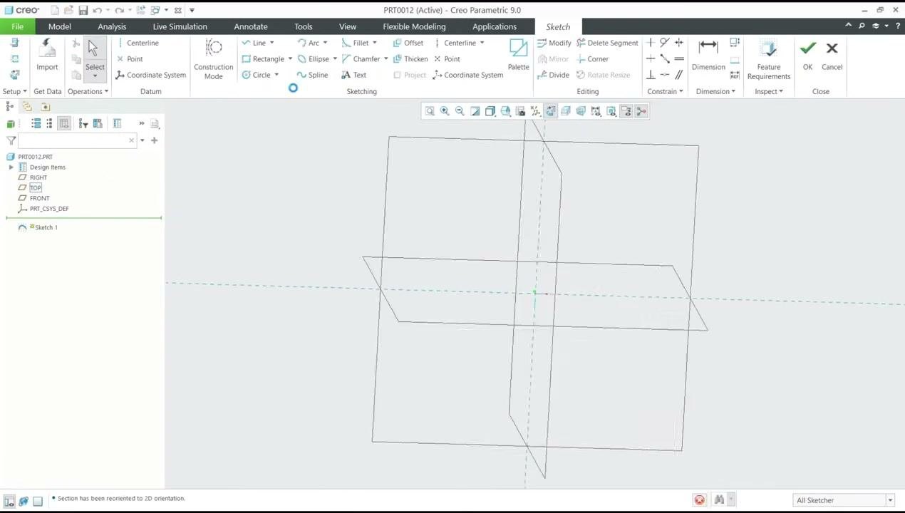
Step 2: Create a base sketch
Select the Top plane from the model tree or the workspace. Then click Sketch to begin a new 2D sketch.
Step 3: Draw a circle with a specific radius
Use the Circle tool to draw a circle centered at the origin. Set the radius to 15 units.
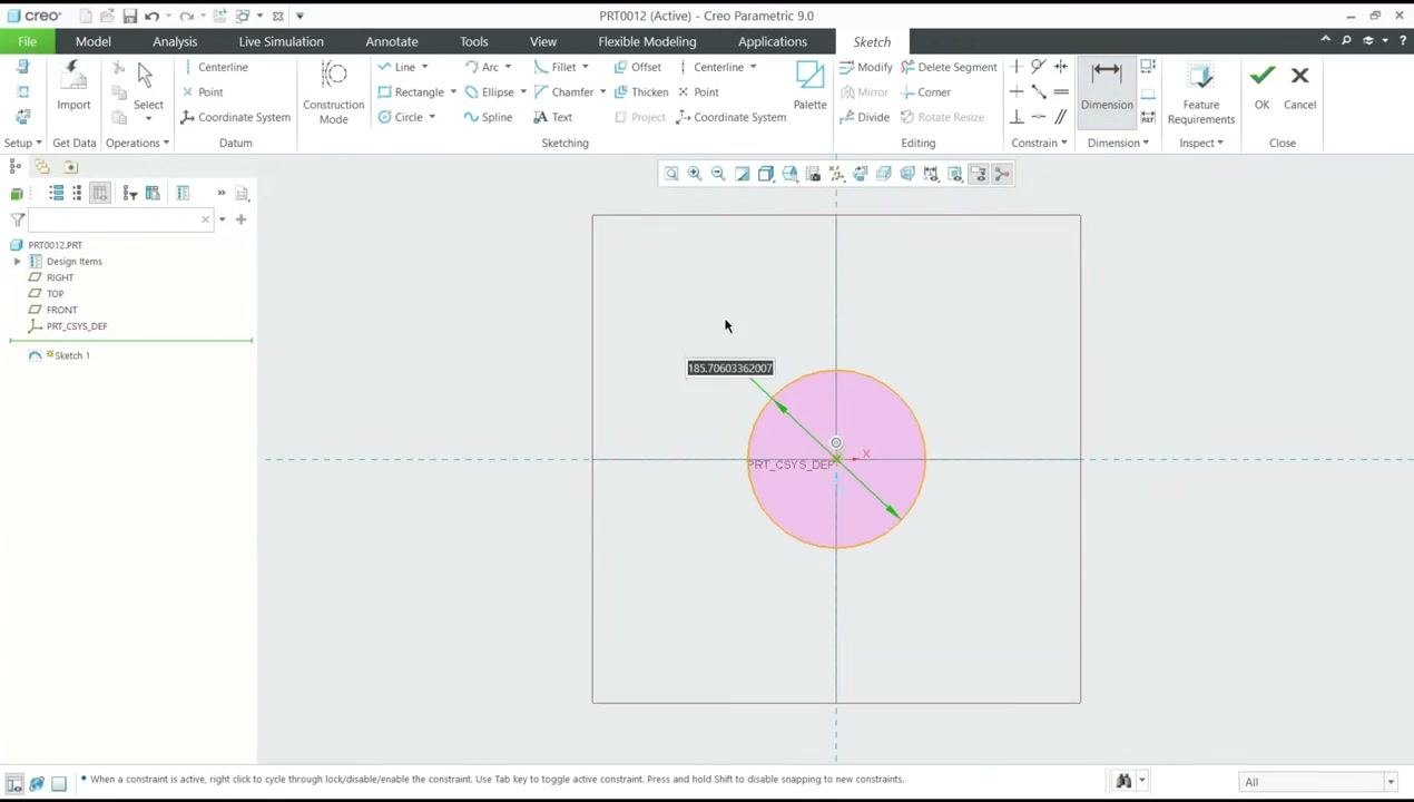
Step 4: Finish the sketch and extrude to 3D
Click OK to finish the sketch. Use the Extrude tool to turn the 2D circle into a 3D cylinder. You can accept the default extrusion or set the height you want.
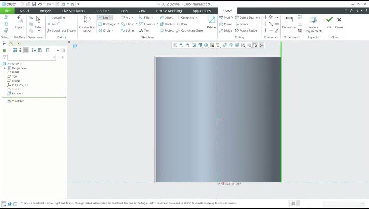
Create the thread path
Step 5: Prepare a sketch for the thread path
Select the Front plane. Click Sketch to start a new sketch on the front face of the cylinder.
Step 6: Draw the thread path
Draw a vertical line from the bottom to the top of the cylinder. This line defines the thread's path.
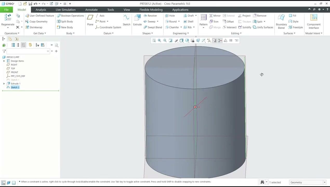
Step 7: Add a centerline for the helix axis
Draw a centerline vertically from the origin point. Then click OK to finish the sketch.
Create the helical sweep and thread profile
Step 8: Start the Helical Sweep
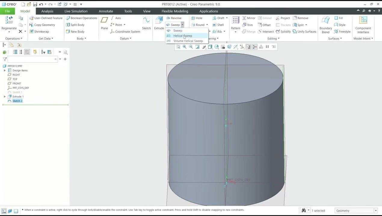
Select the Helical Sweep tool from the Sweep dropdown menu. The sketch for the thread path is selected automatically. For the axis, select the centerline you just created.
Step 9: Sketch the thread section profile
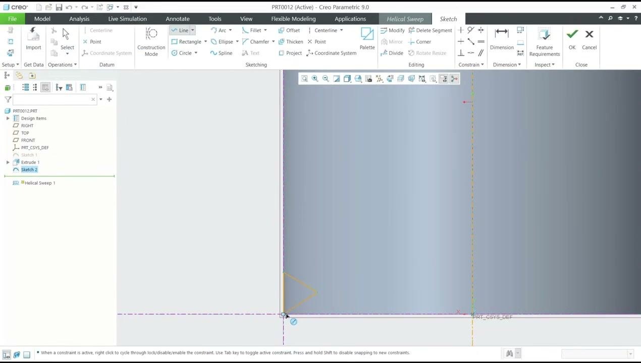
Click Section, and then click Sketch to define the thread's cross-sectional profile. Use the Line tool to draw a triangle at the base of the cylinder, starting from the intersection point.
Step 10: Apply constraints to the thread profile
Use the constraint tools to make the sides of the triangle equal. This gives the thread a symmetric profile.
Step 11: Set the thread pitch dimension
In the thread profile sketch, set the pitch dimension to 1.5 units by entering "1.5" in the dimension field. Click OK to confirm and exit the sketch.
Step 12: Configure the Helical Sweep options
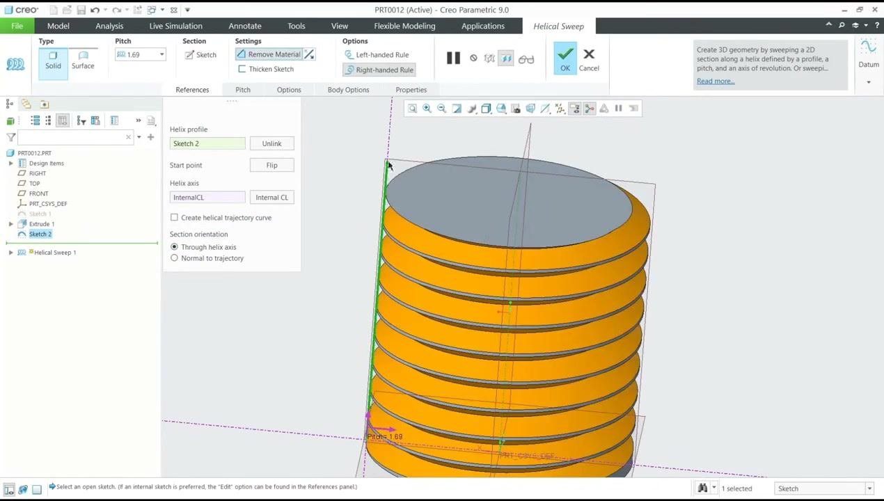
Review the Helical Sweep dialog and check these settings:
- Set Helix profile to "Sketch 2".
- Set Helix axis to "Internal CL".
- Set Pitch to 1.69, as shown in the dialog.
- Select Remove Material if you want to create an internal thread.
- Set Section orientation to "Through helix axis".
Click OK to apply the helical sweep and generate the thread.
Review and save your work
Step 13: Review the generated thread
Inspect the 3D model to confirm the thread runs along the cylinder. Depending on your settings, the thread appears as a helical cut or protrusion around the cylinder.
Step 14: Finalize and save your work
Exit the Helical Sweep tool and return to the main modeling workspace. Review the final threaded part, and then save your part file to preserve your work.
Tips
- Adjust the pitch, profile, and sweep settings to match different thread standards or custom requirements.
- Choose Remove Material for an internal thread, or leave it cleared if you want the thread to protrude from the cylinder.
Summary
You now know how to create threads in Creo Parametric. You built a cylinder, sketched a thread path and helix axis, drew and constrained a triangular profile, and generated the thread with the Helical Sweep tool.
What's next
Continue refining the thread parameters and dimensions to suit your design requirements. Try changing the pitch, the profile shape, or the sweep options to see how they affect the thread.
Generation details: cost, quality tiers
Docsie billed 1,500 credits ($1.05) to analyze this 3-minute video at standard quality. The rewrite, template fill and Word/PDF exports were included. The same video at each quality tier:
| Quality | Frames sampled | Credits | Approx. cost |
|---|---|---|---|
| Draft | every 16-30 s | 750 | $0.52 |
| Standard (this guide) | every 8-15 s | 1,500 | $1.05 |
| Detailed | every 4-7 s | 3,000 | $2.10 |
| Ultra | every 1-3 s | 6,000 | $4.20 |
Credits priced at $0.70 per 1,000; plans include a monthly allowance. Enterprise customers on on-premise or bring-your-own-model deployments run this on their own inference and pay no per-video credits.
Generated by Docsie Video-to-Docs on 2026-11-15 from a 2-minute video. Screenshots are frames from the source video and belong to their creator, Mufasu CAD, whose original is embedded above. If you own this video and want the guide removed or credited differently, contact us and we will act within one business day.