
How to Use Sweep in Creo
This guide explains how to use Sweep in Creo Parametric to create a 3D solid by sweeping a 2D section along a custom trajectory. It also covers how to convert a swept surface into a hollow pipe using the Thicken command, which is a common requirement in piping and tubing design.
Video: #03 Creo Part Modeling- Sweep Command by MD Design Academy. All credit for the demonstration goes to the creator; watch the original on YouTube. The written guide below was generated from this video by Docsie. Creator? Request a change or removal.
This guide explains how to use Sweep in Creo Parametric to create a 3D solid by sweeping a 2D section along a custom trajectory. It also covers how to convert a swept surface into a hollow pipe using the Thicken command, which is a common requirement in piping and tubing design.
Prerequisites
- Creo Parametric installed and launched.
- A part file created or available to open in the file browser.
Creating a 3D sweep
Open the part file
Launch Creo Parametric and open the desired part file from the file browser. The workspace displays the part environment with the model tree and common folders visible on the left.
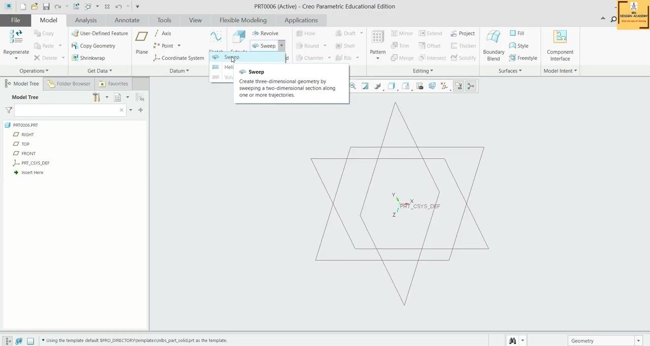
Select the Sweep command
Go to the Model tab in the ribbon menu, then locate and click the Sweep command under the Shapes section. A tooltip appears explaining that this command creates three-dimensional geometry by sweeping a two-dimensional section along one or more trajectories.
Define the sketch plane
After selecting the Sweep command, a dialog prompts you to define the sketch plane. Choose the appropriate plane (for example, TOP-F2 (DATUM_F)) for your sweep path, then set the sketch orientation by selecting a reference (for example, RIGHT+F1 (DATUM PLANE)) and an orientation such as Right. Click Sketch to proceed.
Draw the sweep path (trajectory)
In the sketching environment, use the Spline tool to draw a curved path that will serve as the trajectory for the sweep. Adjust the spline as needed to define the desired path, then click OK to finish the path sketch.
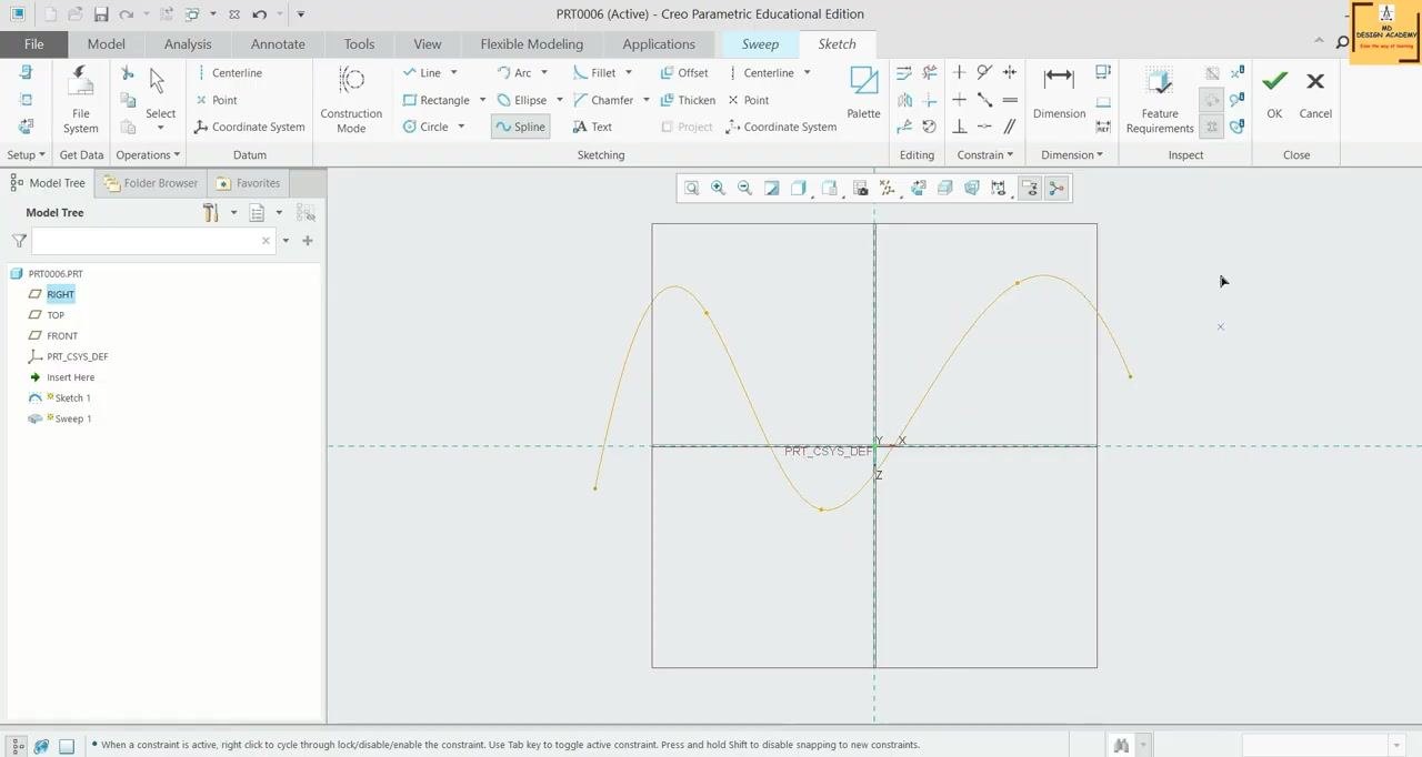
Draw the section to sweep
Resume the Sweep command. The sweep command now uses the drawn spline as the trajectory. The path is highlighted, and you are prompted to define the section to sweep along this path.
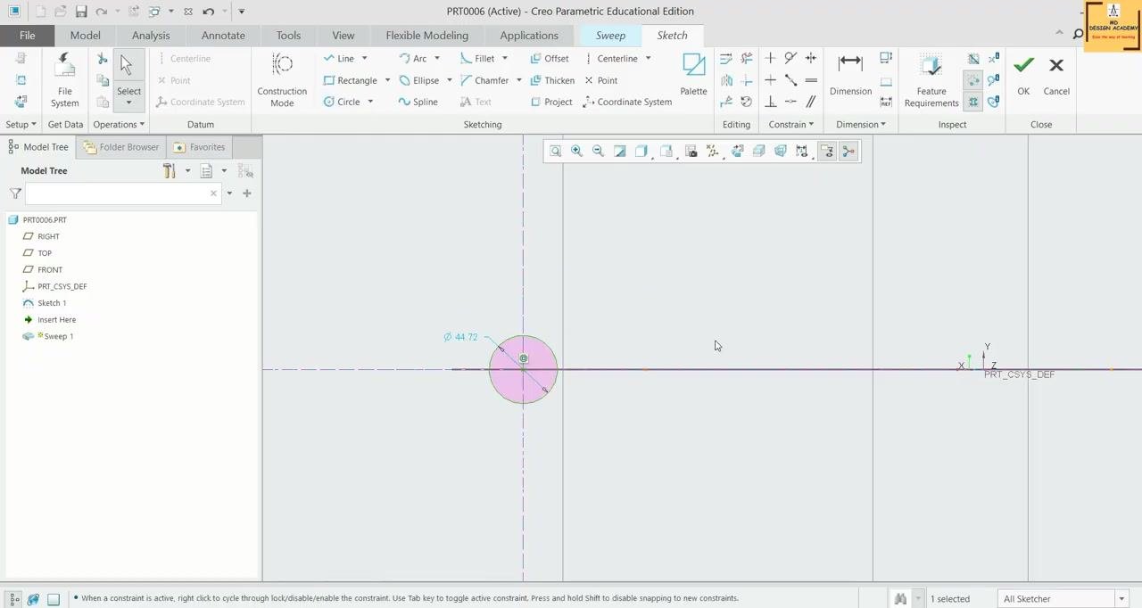
Enter the sketching environment again to define the 2D section that will be swept along the path. For this example, draw a circle with a diameter of 44.72 units at the starting point of the path, and ensure it is properly constrained and positioned. Click OK to complete the section sketch.
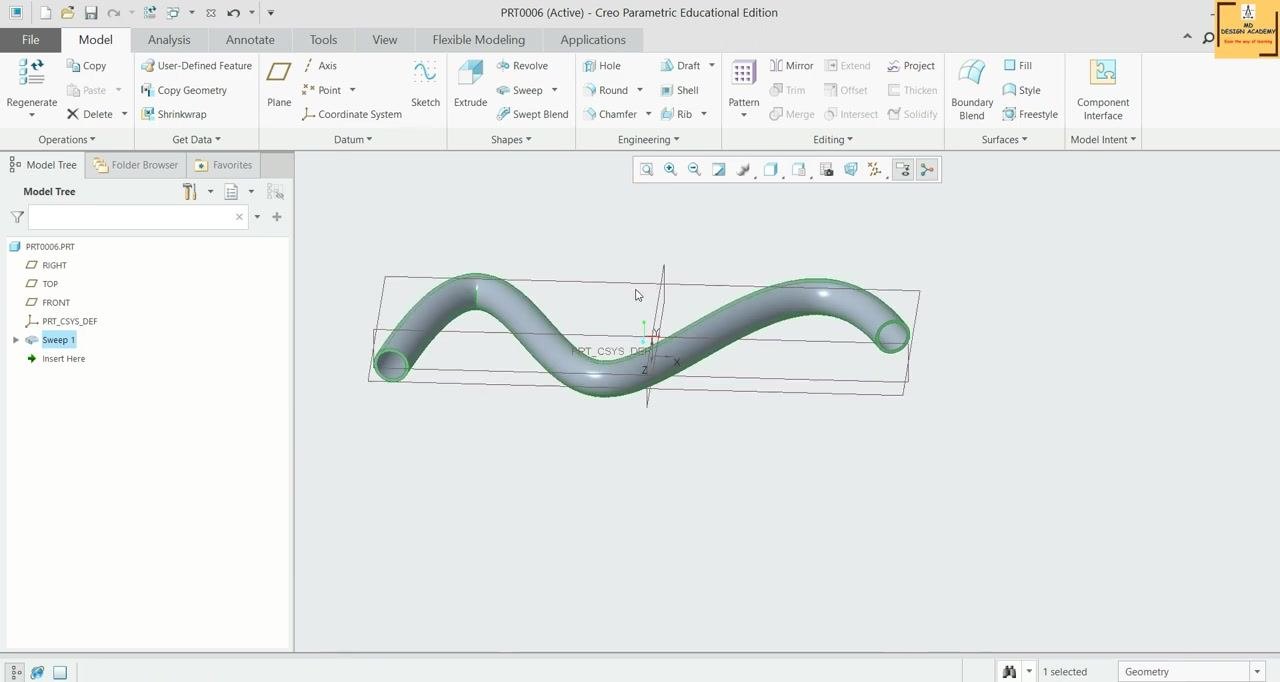
Complete the sweep and generate the 3D solid. The software automatically generates a 3D solid by sweeping the circle along the spline path. The resulting solid is displayed in the modeling area, showing both the path and the swept geometry.
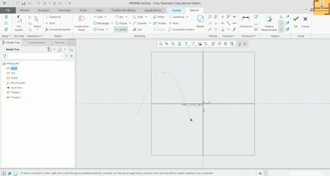
Review the final solid figure
Inspect the resulting 3D solid to ensure it matches the intended design. The solid figure is shown with the sweep path and section visible for reference.
By following these steps, you can convert a 2D section into a 3D solid along a custom path using the Sweep command in Creo Parametric.
Thickening the sweep surface
The following steps show how to convert a swept surface into a hollow pipe by applying a specific wall thickness using the Thicken command.
Switch the sweep to a surface
After creating the sweep, ensure it is set as a surface rather than a solid. Click on the sweep feature in the model tree or graphics area and confirm it is displayed as a surface.
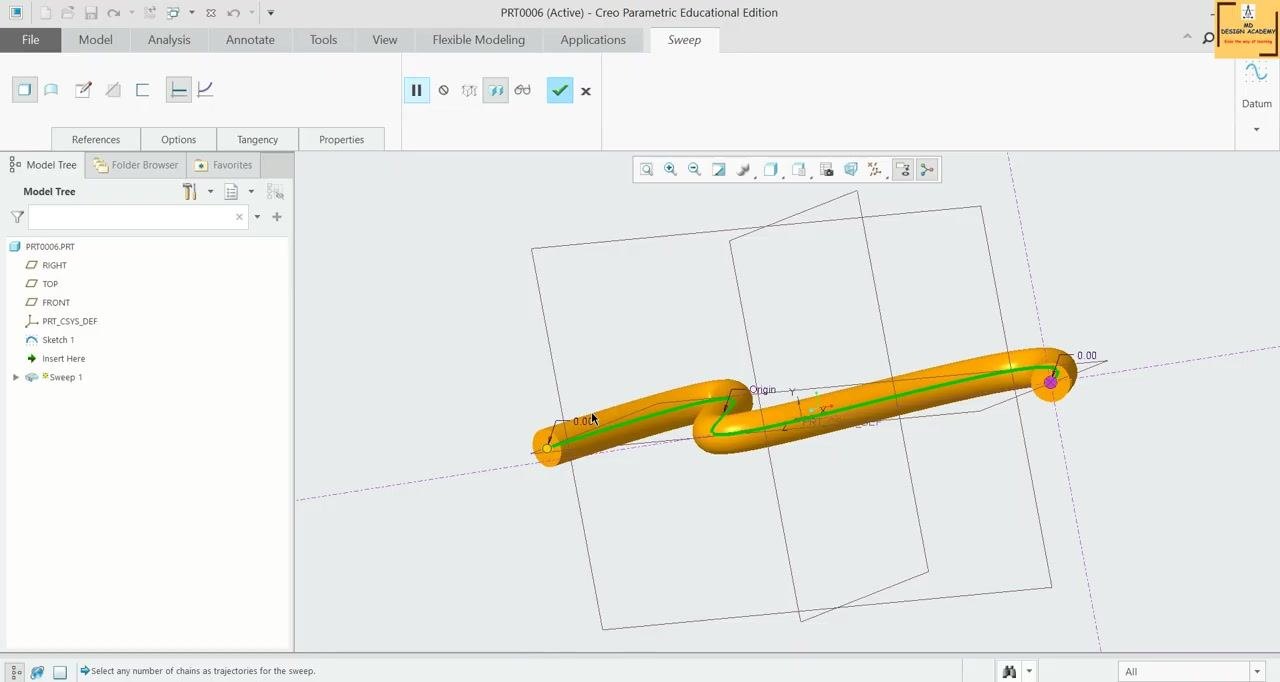
Apply the Thicken command
Select the Thicken command from the ribbon menu. This tool adds a uniform wall thickness to the selected surface, converting it into a solid pipe. Observe the default thickness value (for example, 3.05 units) displayed in the input box.
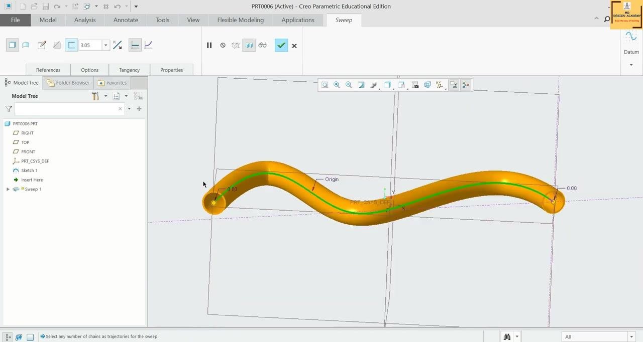
Set the desired thickness
Change the thickness value to 4 units by entering "4.00" in the thickness input box, and confirm the new value is applied to the surface.
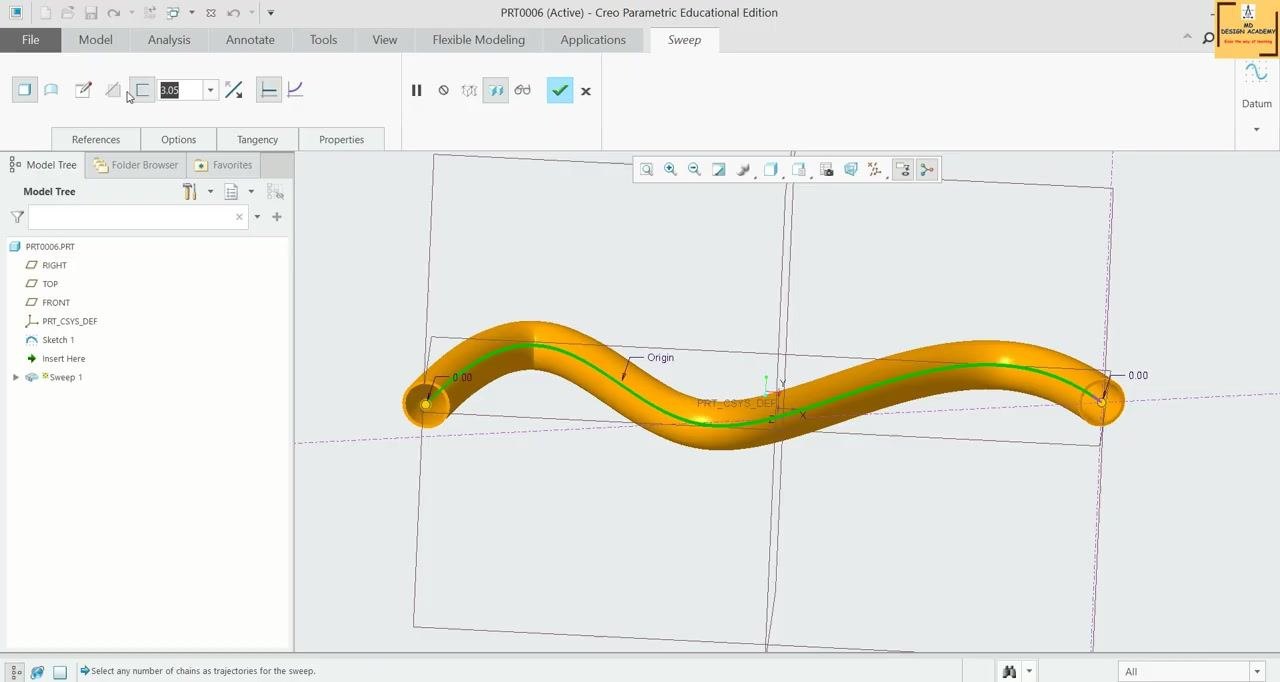
Preview the thickened pipe
Use the preview function to visualize the effect of the applied thickness. Rotate and inspect the model to ensure the wall thickness is applied uniformly along the entire pipe.
Finalize the Thicken operation
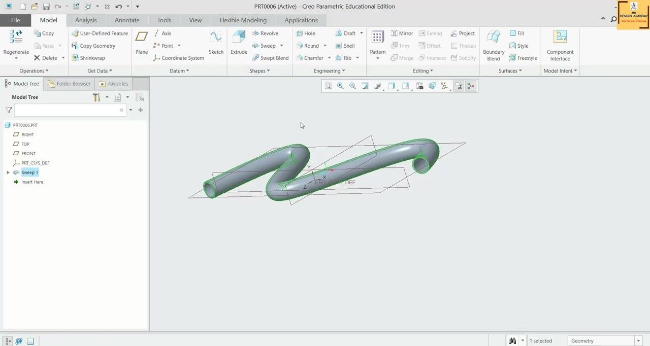
Click the checkmark or confirm button to execute the Thicken command and create the final hollow pipe. The model updates to show the completed pipe with the specified wall thickness.
Review the final pipe geometry
Inspect the finished pipe from different angles to verify the wall thickness and overall shape, ensuring the geometry matches the intended design for piping applications.
Complete the process
The process is now complete. You have created a hollow pipe with a specified wall thickness using the Sweep and Thicken commands. Save your work and exit the modeling environment if finished.
Summary
This guide demonstrated how to use Sweep in Creo Parametric to create a 3D solid from a 2D section swept along a custom trajectory. It also showed how to apply the Thicken command to convert a swept surface into a hollow pipe with a precise wall thickness, a common requirement in piping and tubing design within Creo Parametric.
Generation details: cost, quality tiers
Docsie billed 2,000 credits ($1.40) to analyze this 4-minute video at standard quality. The rewrite, template fill and Word/PDF exports were included. The same video at each quality tier:
| Quality | Frames sampled | Credits | Approx. cost |
|---|---|---|---|
| Draft | every 16-30 s | 1,000 | $0.70 |
| Standard (this guide) | every 8-15 s | 2,000 | $1.40 |
| Detailed | every 4-7 s | 4,000 | $2.80 |
| Ultra | every 1-3 s | 8,000 | $5.60 |
Credits priced at $0.70 per 1,000; plans include a monthly allowance. Enterprise customers on on-premise or bring-your-own-model deployments run this on their own inference and pay no per-video credits.
Generated by Docsie Video-to-Docs on 2026-10-12 from a 3-minute video. Screenshots are frames from the source video and belong to their creator, MD Design Academy, whose original is embedded above. If you own this video and want the guide removed or credited differently, contact us and we will act within one business day.