
How to Measure Dimensions in CATIA
This guide shows you how to measure dimensions in CATIA V5 on a 3D part. You use the Measure Between tool for distances and angles, Measure Item for the radius and center of a circular edge, and Measure Inertia for the part's physical properties. Each dialog shows its results and highlights the measurement on the model in green.
Video: CATIA- HOW TO MEASURE DISTANCE, ANGLE, RADIUS by XpertsCADD Centre (2020). All credit for the demonstration goes to the creator; watch the original on YouTube. The written guide below was generated from this video by Docsie. Creator? Request a change or removal.
This guide shows you how to measure dimensions in CATIA V5 on a 3D part. You use the Measure Between tool for distances and angles, Measure Item for the radius and center of a circular edge, and Measure Inertia for the part's physical properties. Each dialog shows its results and highlights the measurement on the model in green.
Prerequisites
Before you start, make sure the following are in place:
- The part file is loaded in CATIA V5.
- The workspace shows the part with its planes (
xy plane,yz plane,zx plane) andPartBodyin the tree view. - The toolbars Sketch-Based Features, Dress-Up Features, Reference Elements, and Product View are accessible.
- The Tools palette is visible at the bottom of the window.
No measurements have been performed yet at this point.
Start the Measure Between tool
In the Measure toolbar, click Measure Between. Its icon shows two arrows pointing left and right. The cursor highlights the tool as you select it.
Measure the distance between two planes
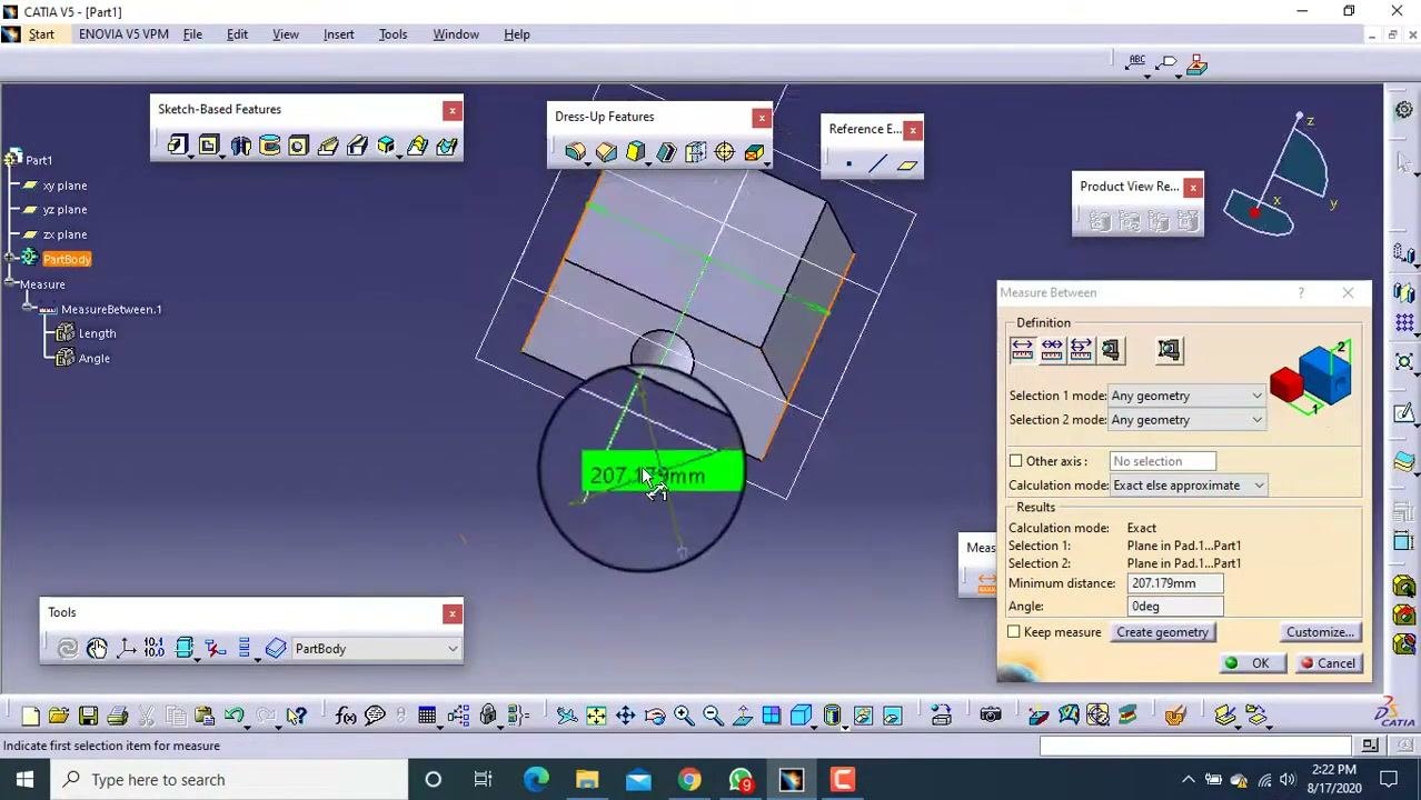
Select two planes on the part to measure the minimum distance between them. The Measure Between dialog appears with these values:
- Selection 1 mode: Any geometry
- Selection 2 mode: Any geometry
- Calculation mode: Exact
- Selection 1: Plane in Pad.1...Part1
- Selection 2: Plane in Pad.1...Part1
- Minimum distance: 207.179 mm
- Angle: 0 deg
The measured distance appears in green on the model.
Rotate the model to inspect the measurement
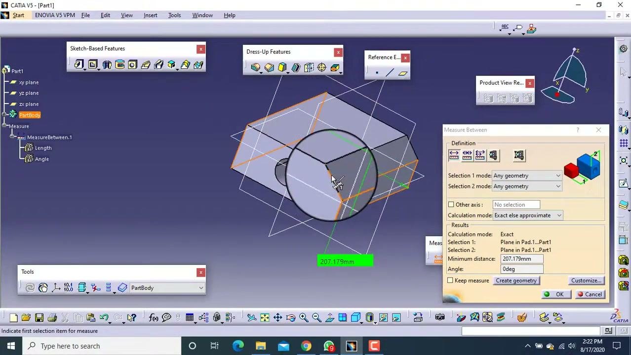
Rotate the 3D model to see the measured distance from another angle. The selected planes and the 207.179 mm measurement stay highlighted. The Measure Between dialog stays open, so you can adjust or confirm the measurement.
Measure the distance between two lines
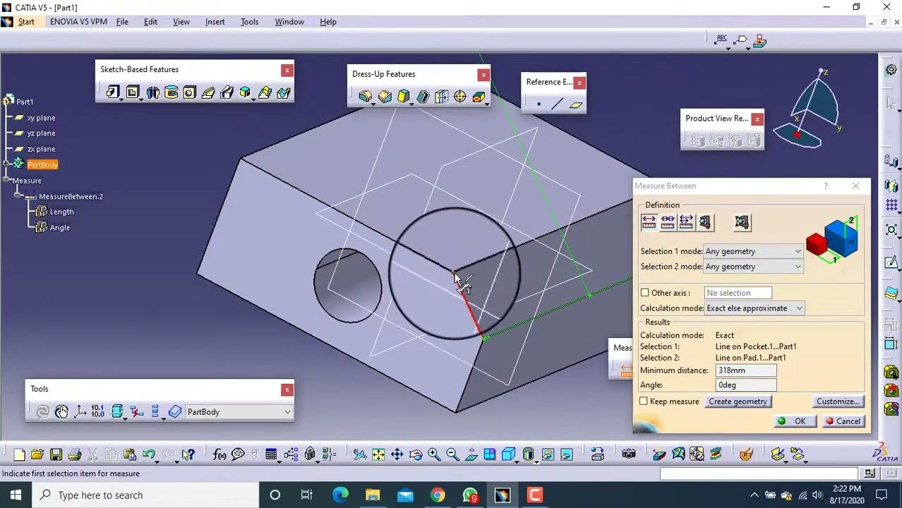
Select a line on the pocket feature and a line on the pad feature. The dialog updates with these values:
- Selection 1: Line on Pocket.1...Part1
- Selection 2: Line on Pad.1...Part1
- Minimum distance: 318 mm
- Angle: 0 deg
The distance appears in green on the model.
Measure the distance between a line and a surface
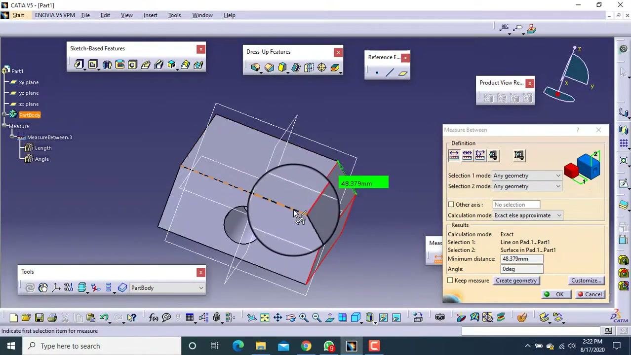
Select a line on the pad and a surface on the pad. The dialog updates with these values:
- Selection 1: Line on Pad.1...Part1
- Selection 2: Surface in Pad.1...Part1
- Minimum distance: 48.379 mm
- Angle: 0 deg
The distance appears in green on the model.
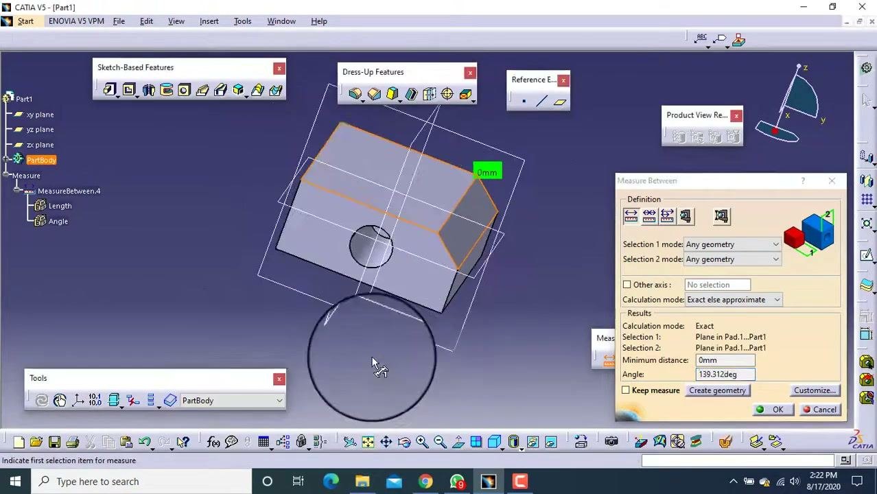
Measure the angle between two planes
Select two planes on the part. The dialog updates with these values:
- Selection 1: Plane in Pad.1...Part1
- Selection 2: Plane in Pad.1...Part1
- Minimum distance: 0 mm
- Angle: 139.312 deg
The angle appears in green on the model.
Measure the distance between two planes in a pocket
Select two planes inside the pocket feature. The dialog updates with these values:
- Selection 1: Plane in Pocket.1...Part1
- Selection 2: Plane in Pocket.1...Part1
- Minimum distance: 160 mm
- Angle: 0 deg
The distance appears in green on the model.
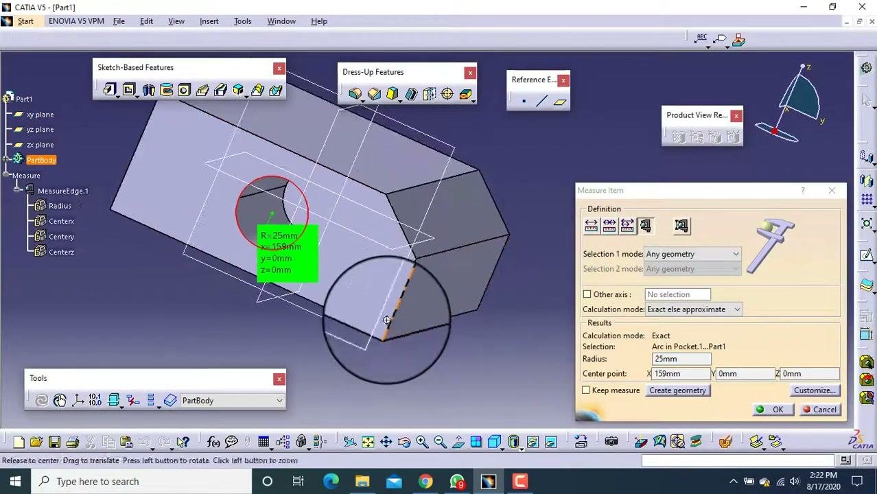
Measure the radius and center of a circular edge
Select the arc or circular edge in the pocket feature. The Measure Item dialog appears and shows:
- Radius: 25 mm
- Center point: x = 159 mm, y = 0 mm, z = 0 mm
The radius and center coordinates appear in green on the model.
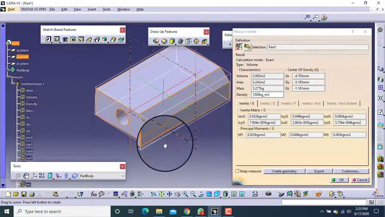
Analyze the inertia and physical properties of the part
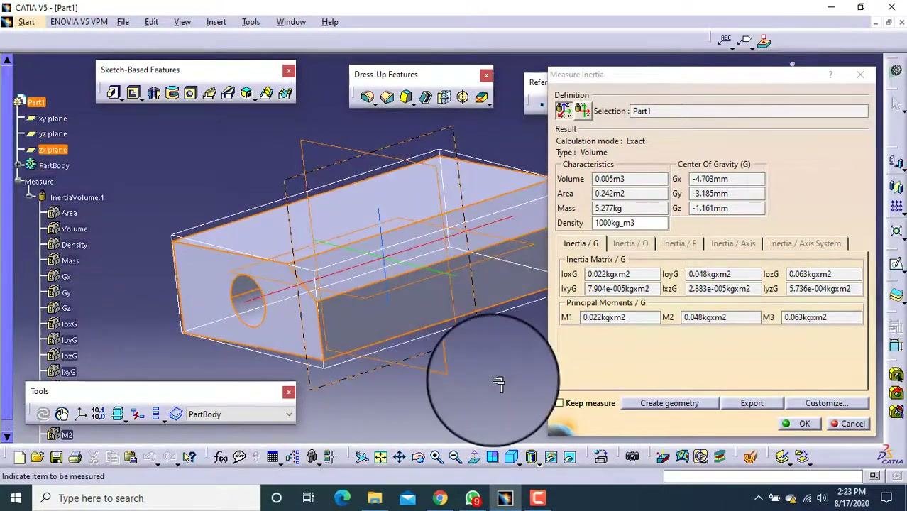
Open the Measure Inertia dialog for the part. The dialog shows these values:
- Volume: 0.005 m^3
- Area: 0.242 m^2
- Mass: 5.277 kg
- Density: 1000 kg/m^3
- Center of gravity: Gx = -4.703 mm, Gy = -3.185 mm, Gz = -1.161 mm
- The inertia matrix and principal moments
The part is highlighted, and the dialog stays visible so you can review or export the results.
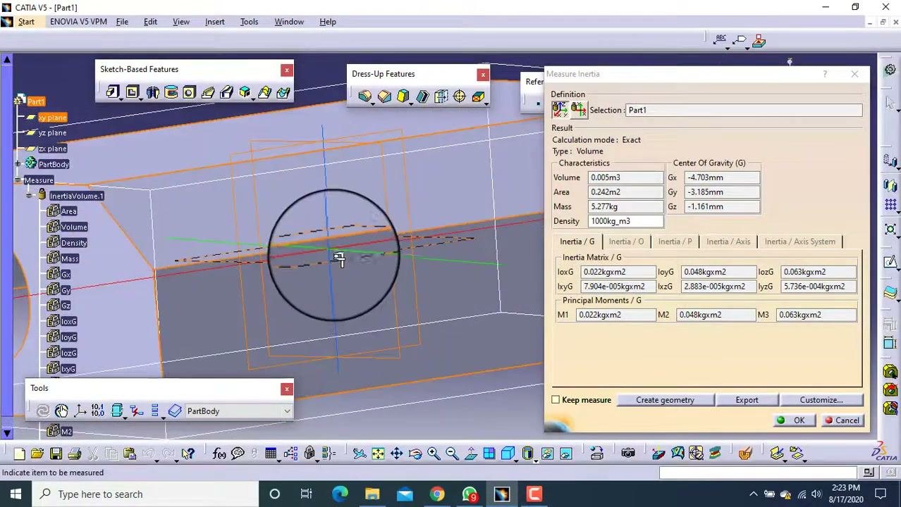
Inspect the model from different angles
Rotate and zoom in on the model to examine the geometry and the highlighted features used in the inertia calculation. The Measure Inertia dialog stays open and shows the same values. The circular feature and reference planes are clearly visible, which helps you verify the geometry you selected.
Return to the default view
Rotate or zoom out to return to a standard isometric view of the part. The Measure Inertia dialog is still open. The part, reference planes, and highlighted features remain visible for a final review.
Close the Measure Inertia dialog
Click OK or Cancel, as appropriate, to close the Measure Inertia dialog. The workspace returns to the standard CATIA V5 environment with the part and reference planes visible. The Sketch-Based Features, Dress-Up Features, Reference Elements, and Measure toolbars remain accessible.
Summary
You now know how to measure dimensions in CATIA V5. You measured distances between planes, lines, and surfaces, and the angle between two planes. You also measured the radius and center of a circular edge and reviewed the part's volume, area, mass, density, and center of gravity. Each measurement dialog gives detailed results and options to create geometry or export data as needed.
Generation details: cost, quality tiers
Docsie billed 1,500 credits ($1.05) to analyze this 3-minute video at standard quality. The rewrite, template fill and Word/PDF exports were included. The same video at each quality tier:
| Quality | Frames sampled | Credits | Approx. cost |
|---|---|---|---|
| Draft | every 16-30 s | 750 | $0.52 |
| Standard (this guide) | every 8-15 s | 1,500 | $1.05 |
| Detailed | every 4-7 s | 3,000 | $2.10 |
| Ultra | every 1-3 s | 6,000 | $4.20 |
Credits priced at $0.70 per 1,000; plans include a monthly allowance. Enterprise customers on on-premise or bring-your-own-model deployments run this on their own inference and pay no per-video credits.
Generated by Docsie Video-to-Docs on 2026-11-15 from a 2-minute video. Screenshots are frames from the source video and belong to their creator, XpertsCADD Centre, whose original is embedded above. If you own this video and want the guide removed or credited differently, contact us and we will act within one business day.