
How to Apply a Coincidence Constraint in CATIA
This guide shows you how to apply a coincidence constraint in CATIA V5 to anchor a line's endpoints to vertical and horizontal reference lines. You draw a slanted line in the sketch environment, constrain each endpoint to a reference line, and test how the constraint limits movement. You then add dimensions to define the line fully.
Video: 17. Coincidence Constraint- CATIA sketcher by Mechanical design (2018). All credit for the demonstration goes to the creator; watch the original on YouTube. The written guide below was generated from this video by Docsie. Creator? Request a change or removal.
This guide shows you how to apply a coincidence constraint in CATIA V5 to anchor a line's endpoints to vertical and horizontal reference lines. You draw a slanted line in the sketch environment, constrain each endpoint to a reference line, and test how the constraint limits movement. You then add dimensions to define the line fully.
Prerequisites
- CATIA V5 is installed and running.
- You have a part file that contains
Sketch.1underGeometrical Set.1.
Open the sketch environment
Step 1: Open the sketch
- Launch CATIA V5 and open your part file.
- In the tree on the left, double-click
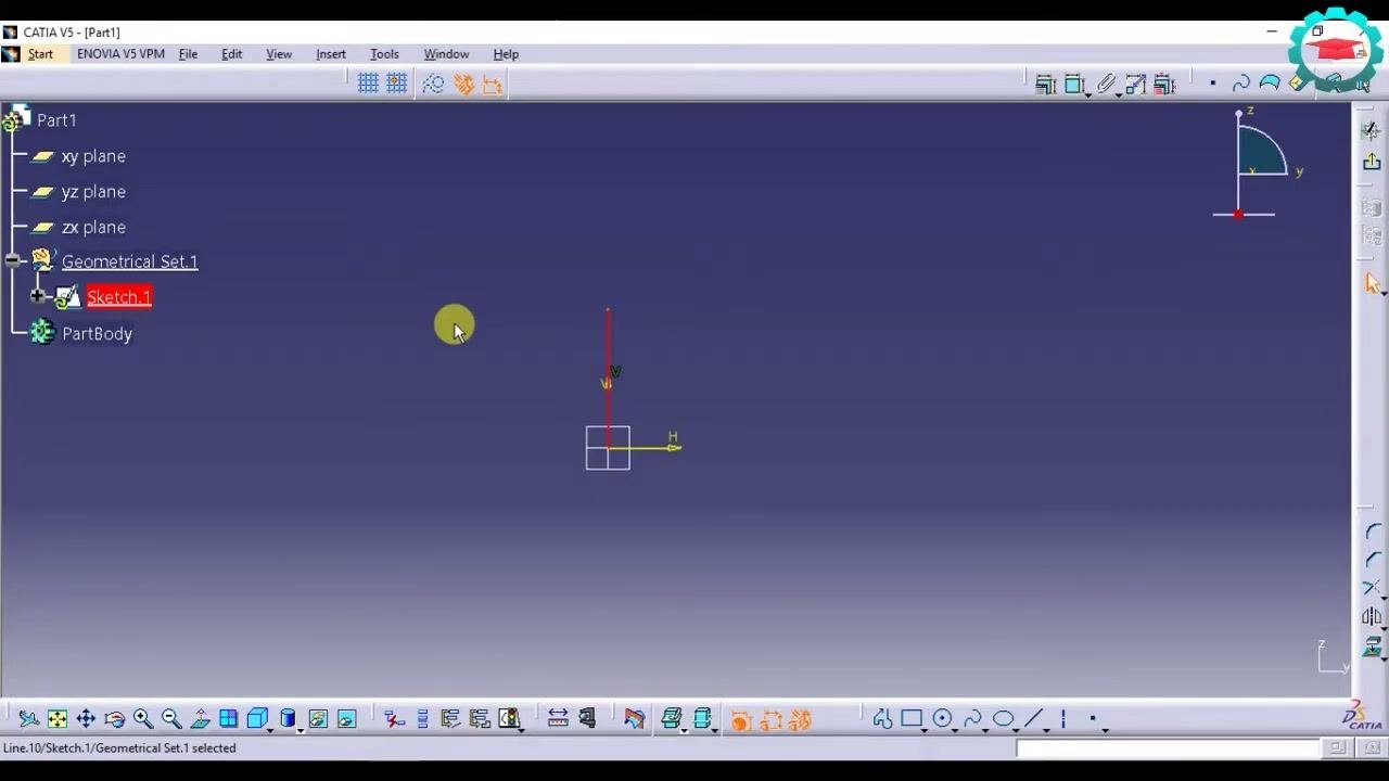
Sketch.1underGeometrical Set.1to enter the sketching environment.
The workspace shows the coordinate system and the reference planes (xy plane, yz plane, zx plane). A vertical reference line is visible in the sketch.
Draw the line to constrain
Step 2: Draw a new line in space
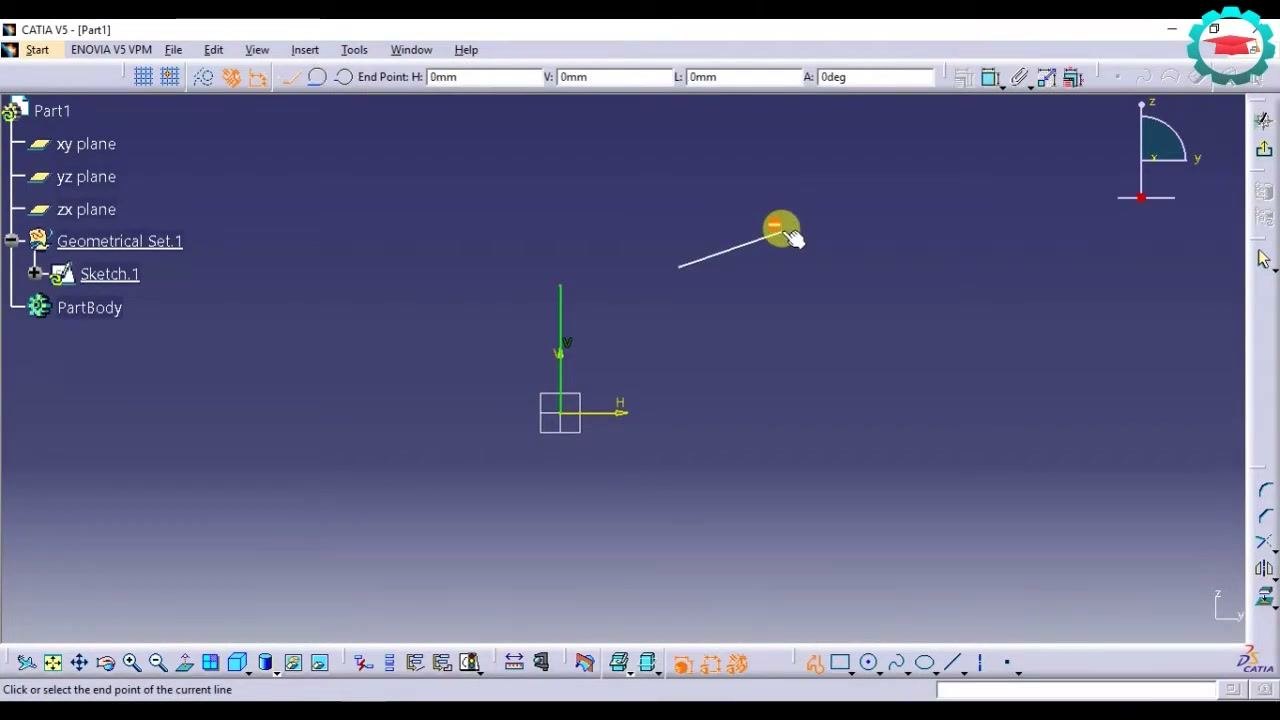
- Select the line tool from the toolbar.
- Click in the workspace to start a new line away from the origin and the reference lines.
- Click again to complete the line.
You now have a slanted line in space.
Apply the first coincidence constraint
Step 3: Select the point and the reference line
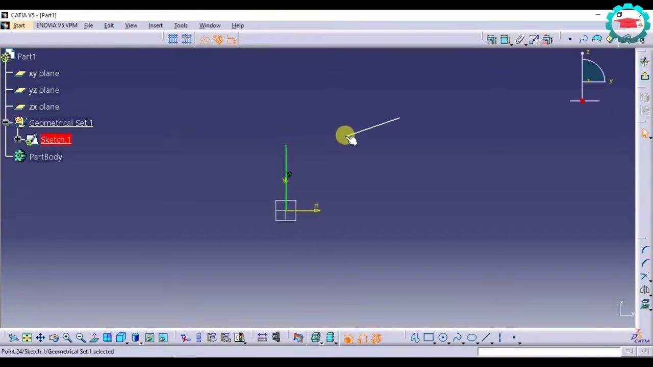
- Click the endpoint of the slanted line that you want to constrain. The selected point is highlighted.
- Hold
Ctrland select the vertical reference line in the sketch.
Both the endpoint and the vertical line are now selected.
Step 4: Apply the coincidence constraint
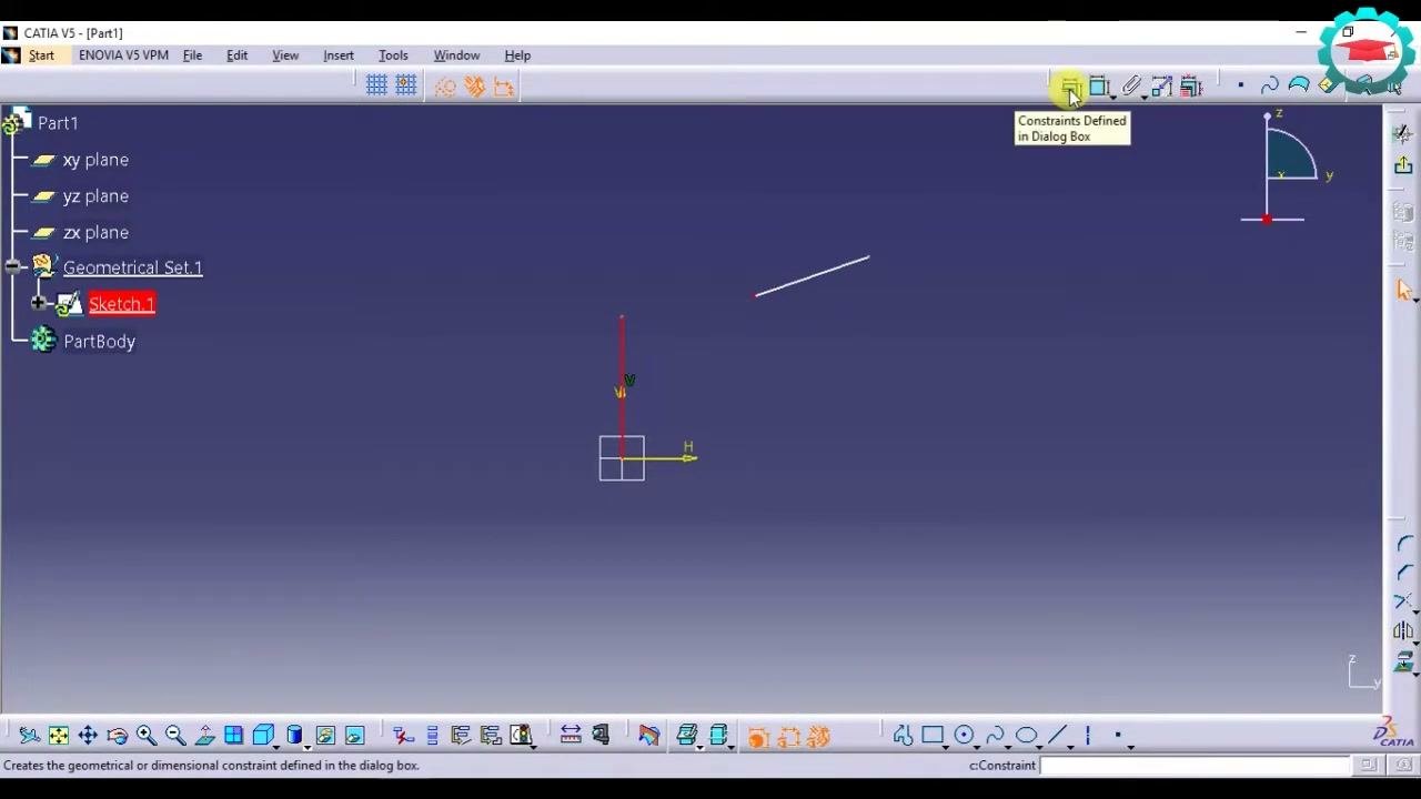
- In the top toolbar, click the Constraints Defined in Dialog Box button (the icon with a constraint symbol).
The Constraint Definition dialog box appears.
- In the Constraint Definition dialog box, check Coincidence.
- Click OK.
The endpoint of the slanted line is now coincident with the vertical reference line.
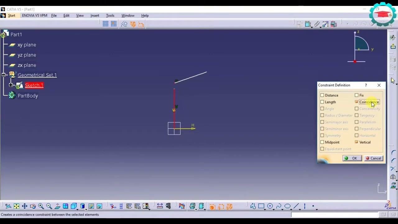
Step 5: Test the constraint
Try to move the slanted line. It moves only along the vertical reference line because its endpoint is constrained.
Apply a second coincidence constraint
Step 6: Draw a horizontal reference line
- Select the line tool again.
- Draw a horizontal line from the origin or another reference point.
The horizontal line appears in the sketch.
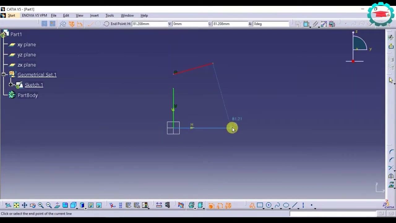
Step 7: Select the other endpoint and the horizontal line
- Click the other endpoint of the slanted line.
- Hold
Ctrland select the horizontal reference line.
Step 8: Apply the second coincidence constraint
- Open the Constraint Definition dialog box again.
- Check Coincidence.
- Click OK.
Both endpoints of the slanted line are now coincident: one with the vertical line and one with the horizontal line.
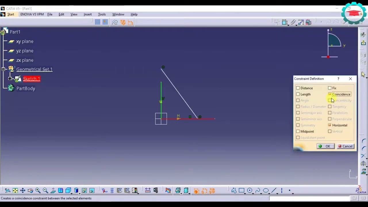
Add dimensions to complete the definition
Step 9: Dimension the constrained line
The slanted line is now fully constrained and cannot move independently. Its endpoints are locked to the intersection points of the reference lines. You can add dimensions to define it completely.
- Select the dimension tool from the toolbar.
- Click the vertical reference line and the coincident point to add a vertical dimension (for example, 50).
- Click the horizontal reference line and the coincident point to add a horizontal dimension (for example, 85).
The line is now fully defined by both the coincidence constraints and the dimensions.
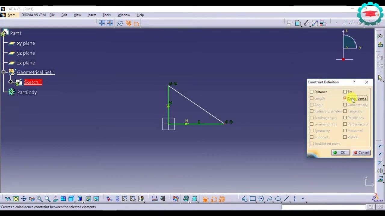
Summary
You applied coincidence constraints to a line in CATIA V5 and anchored its endpoints to a vertical and a horizontal reference line. These constraints restrict how the line can move. Adding dimensions then defined the line fully.
What's next
- Repeat the steps with other lines or points in your sketch.
- Use dimensions with coincidence constraints to define your sketch geometry fully.
Generation details: cost, quality tiers
Docsie billed 2,000 credits ($1.40) to analyze this 4-minute video at standard quality. The rewrite, template fill and Word/PDF exports were included. The same video at each quality tier:
| Quality | Frames sampled | Credits | Approx. cost |
|---|---|---|---|
| Draft | every 16-30 s | 1,000 | $0.70 |
| Standard (this guide) | every 8-15 s | 2,000 | $1.40 |
| Detailed | every 4-7 s | 4,000 | $2.80 |
| Ultra | every 1-3 s | 8,000 | $5.60 |
Credits priced at $0.70 per 1,000; plans include a monthly allowance. Enterprise customers on on-premise or bring-your-own-model deployments run this on their own inference and pay no per-video credits.
Generated by Docsie Video-to-Docs on 2026-11-15 from a 3-minute video. Screenshots are frames from the source video and belong to their creator, Mechanical design, whose original is embedded above. If you own this video and want the guide removed or credited differently, contact us and we will act within one business day.