
How to Change the Axis System in CATIA
If you want to know how to change the axis system in CATIA V5, you can insert a custom axis system into a Part Design document. This guide shows you how to define its origin, X axis, and reference surface, rotate it by an angle, and reverse individual axis directions. You can then apply the result to your part.
Video: Catia V5 Powerful Tricks #132|Custom Axis System|Axis Rotation with Control Surface by howENGINEERSdoit! (2013). All credit for the demonstration goes to the creator; watch the original on YouTube. The written guide below was generated from this video by Docsie. Creator? Request a change or removal.
If you want to know how to change the axis system in CATIA V5, you can insert a custom axis system into a Part Design document. This guide shows you how to define its origin, X axis, and reference surface, rotate it by an angle, and reverse individual axis directions. You can then apply the result to your part.
Prerequisites
Before you begin, make sure you have the following:
- CATIA V5 installed and ready to launch
- A 3D object in a Part Design document. Step 2 shows you how to create a simple one.
Open a new Part Design document
Start CATIA V5 and create a new part document in the Part Design workbench.
- Launch CATIA V5.
- Go to Start > Mechanical Design > Part Design.
- Select Part Design to open a new part document.
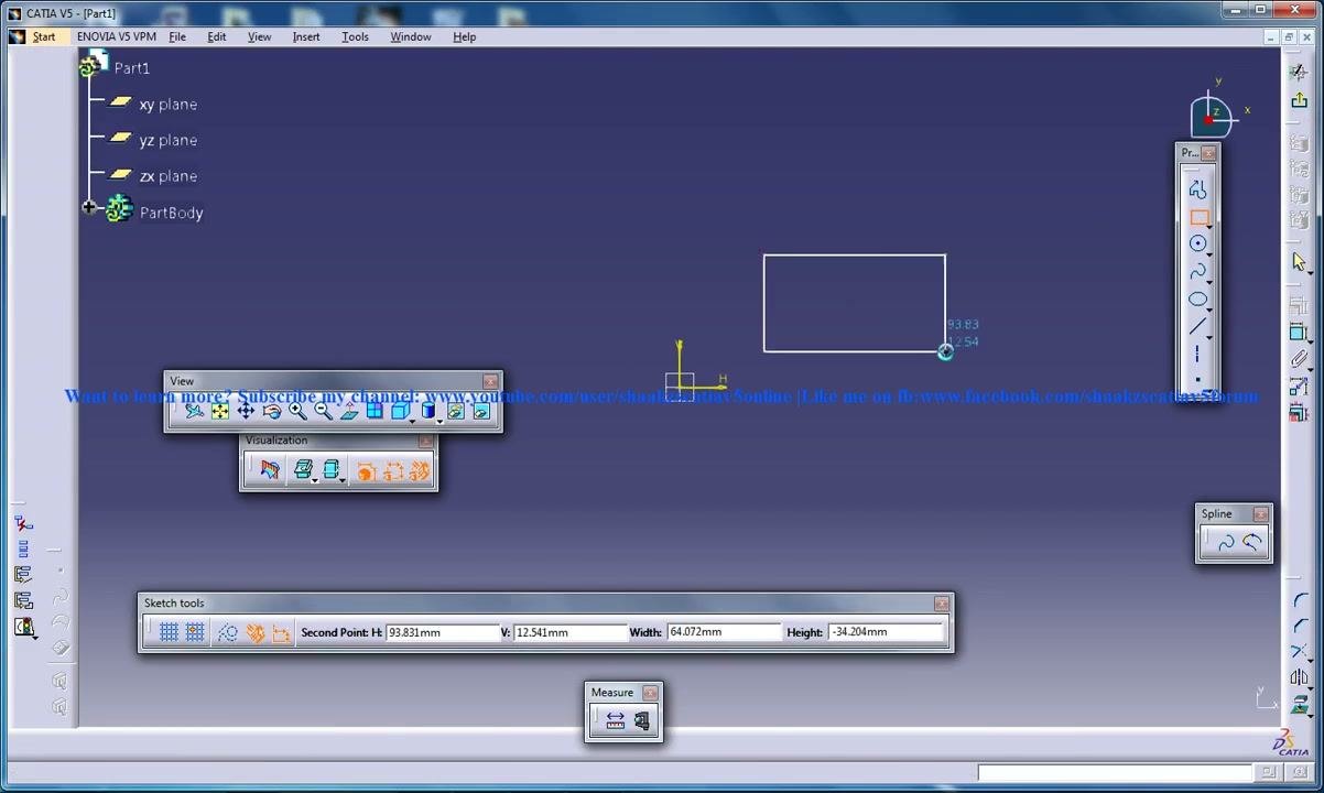
Create a basic 3D object
Create a simple object that gives you a vertex, an edge, and a face to select later.
- In the Part Design workbench, create a simple sketch, such as a rectangle.
- Pad the sketch to form a 3D object. Use the sketch and pad tools as needed.
Insert an axis system
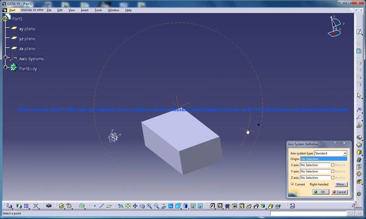
Open the Axis System Definition dialog from the top menu.
- Select Insert > Axis System....
- The Axis System Definition dialog opens.
Set the axis system type to Axis rotation
In the Axis System Definition dialog, set Axis system type to Axis rotation. The dialog then prompts you for the origin, axes, reference, and angle.
Specify the origin
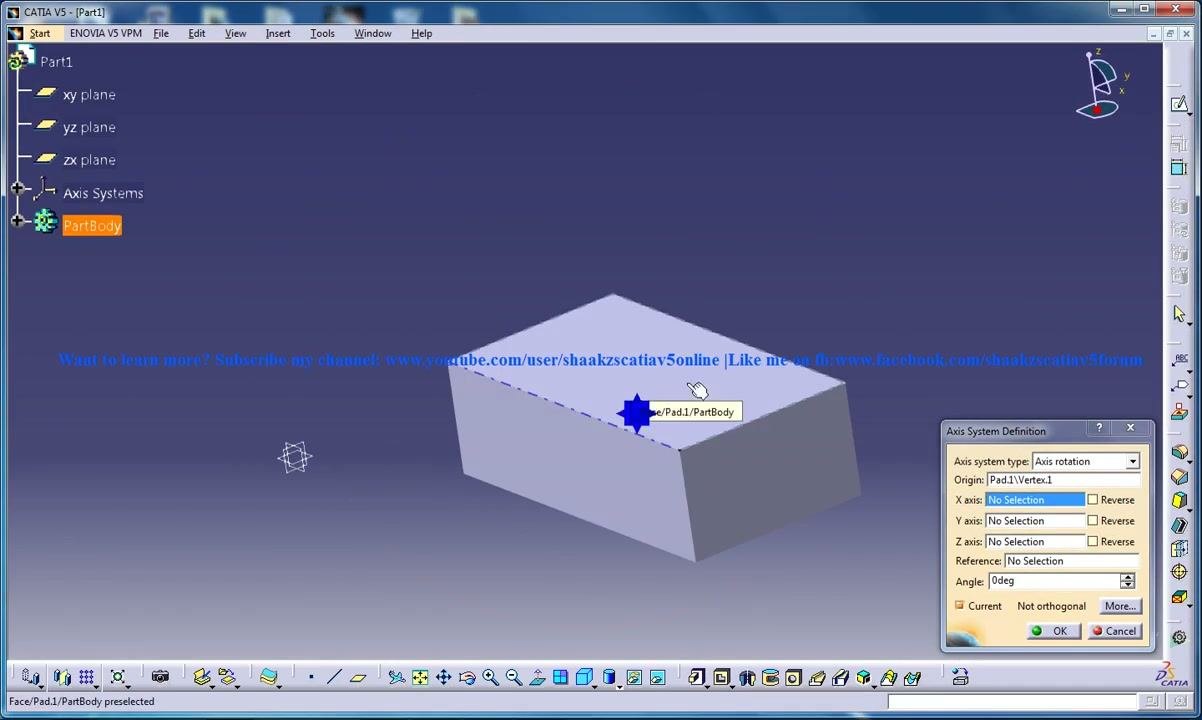
Choose a point on your object as the origin of the new axis system.
- Click the selection box next to Origin.
- Select a vertex on your 3D object, for example Pad.1\Vertex.1.
CATIA highlights the selected vertex.
Define the X axis
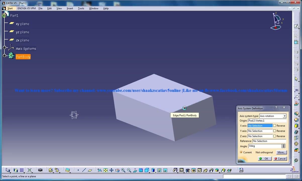
Choose an edge to set the direction of the X axis.
- Click the selection box next to X axis.
- Select an edge on your object, for example Pad.1\Edge.1.
CATIA highlights the selected edge.
Select the reference surface
Choose the surface that the axis rotation is measured against.
- Click the selection box next to Reference.
- Select a face on your object, for example Pad.1\Face.1.
CATIA uses this surface to define the rotation of the axis.
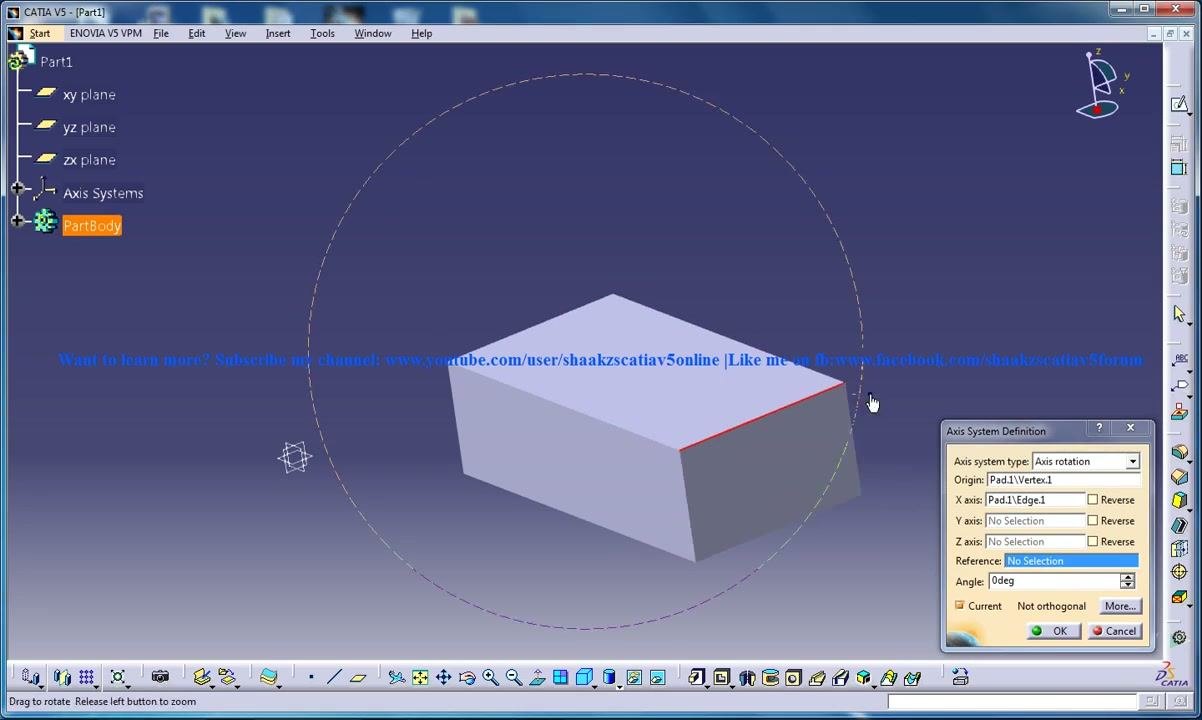
Review the axis system settings
Before you confirm, check that the Axis System Definition dialog contains these values:
- Axis system type: Axis rotation
- Origin: Pad.1\Vertex.1
- X axis: Pad.1\Edge.1
- Reference: Pad.1\Face.1
- Angle: 0deg, or the rotation angle you want
The axis system preview updates to reflect your selections.
Confirm the axis system on the object
Check that the axis system appears correctly on your object, with the origin, X axis, and reference surface as you specified.
This method is especially useful when you need a custom axis that rotates at a specific angle relative to a reference surface. Always verify your selections in the dialog before you confirm.
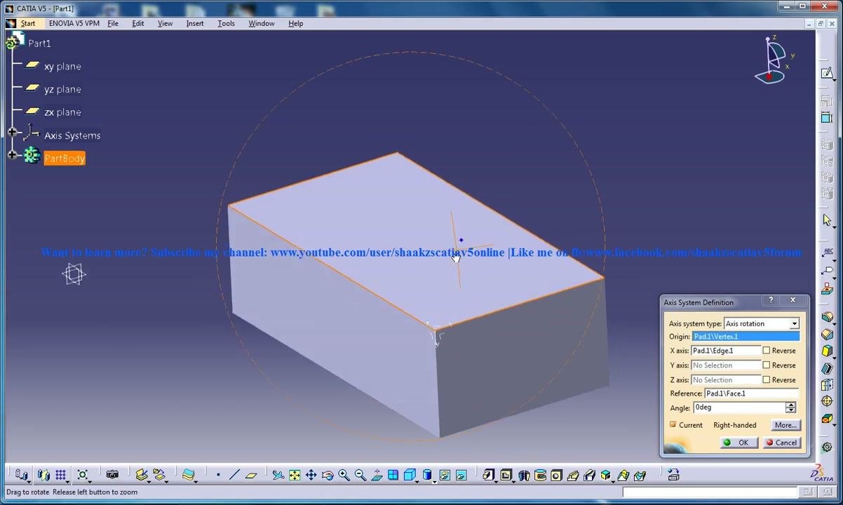
Check the axis rotation relative to the reference surface
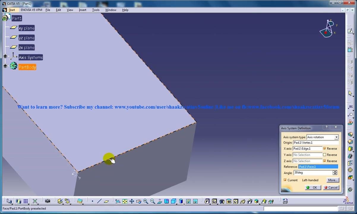
The axis system rotates with respect to the reference surface you selected, for example Pad.1\Face.1. When you set an angle such as 30 degrees, the Z axis rotates by that angle relative to the reference surface.
The rotation preview appears as an orange arc or circle around the object.
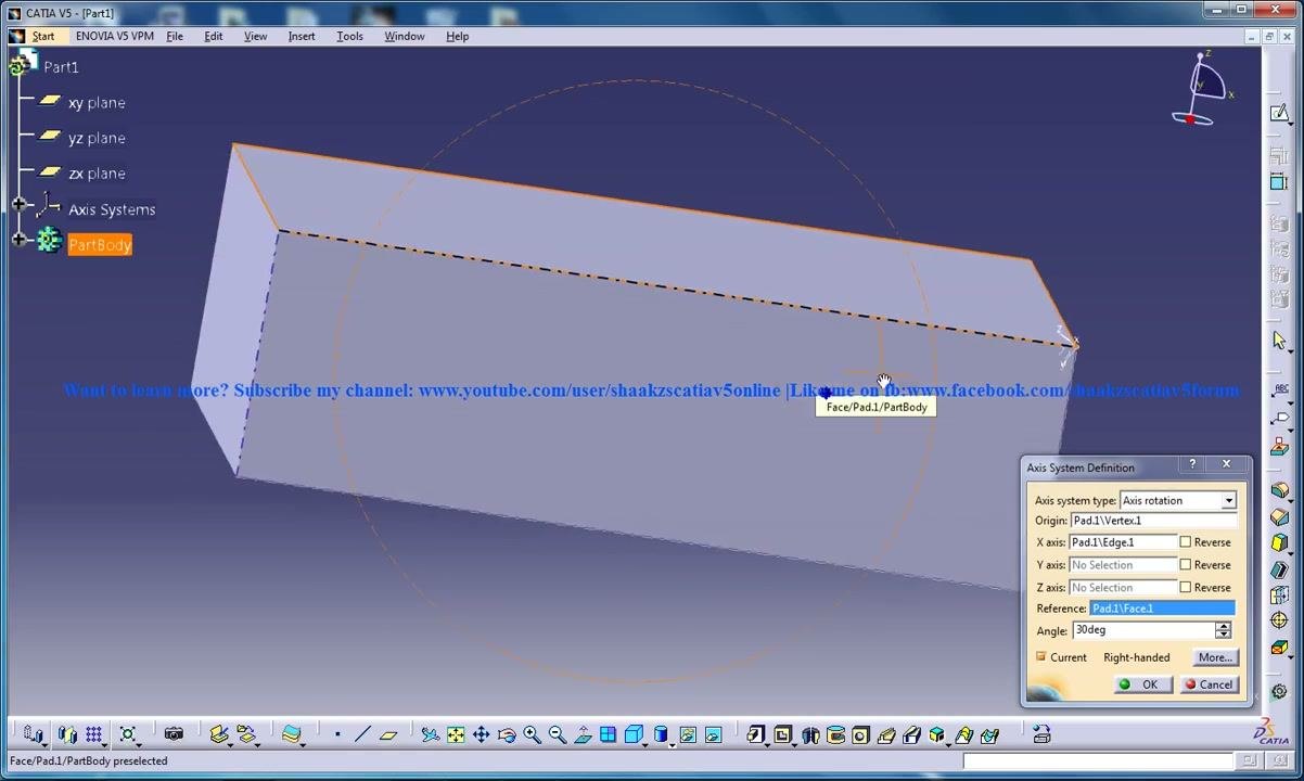
Reverse axis directions to change the axis system in CATIA
You can flip the direction of each axis individually. In the Axis System Definition dialog, find the Reverse checkboxes next to the X, Y, and Z axis fields.
- Z axis: Select Reverse next to the Z axis to flip its direction.
- X axis: Select Reverse next to the X axis to flip its direction.
- Y axis: Select Reverse next to the Y axis to flip its direction.
When you select an option, the corresponding axis changes direction in the 3D preview. This helps you align the axis system exactly as your design or manufacturing requirements need.
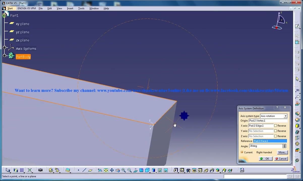
Preview the updated orientation
After you adjust the axis directions, review the 3D preview to make sure the axis system is oriented the way you want. It should reflect any reversions or rotations you applied.
If needed, you can select different faces, edges, or vertices to refine the axis system further.
Finalize the axis system
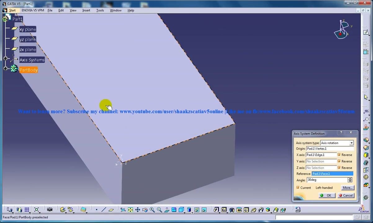
When you are satisfied with the orientation and rotation, click OK in the Axis System Definition dialog to apply the changes.
CATIA adds the custom axis system to your part under the Axis Systems node in the specification tree.
Tips
- Use the axis reversion options when the default axis orientation does not match your design intent.
- Use the 3D preview to confirm the axis directions visually before you finalize.
- To edit the axis system later, double-click it in the specification tree.
Summary
You now know how to change the axis system in CATIA V5 using the axis rotation method. You inserted an axis system, defined its origin, X axis, and reference surface, set a rotation angle, and reversed axis directions where needed. This gives you full control over the orientation and direction of your custom axis system for precise alignment in your modeling.
What's next
- Select different vertices, edges, and faces to see how they change the axis system.
- Double-click an existing axis system in the specification tree to adjust its angle or axis directions.
Generation details: cost, quality tiers
Docsie billed 1,500 credits ($1.05) to analyze this 3-minute video at standard quality. The rewrite, template fill and Word/PDF exports were included. The same video at each quality tier:
| Quality | Frames sampled | Credits | Approx. cost |
|---|---|---|---|
| Draft | every 16-30 s | 750 | $0.52 |
| Standard (this guide) | every 8-15 s | 1,500 | $1.05 |
| Detailed | every 4-7 s | 3,000 | $2.10 |
| Ultra | every 1-3 s | 6,000 | $4.20 |
Credits priced at $0.70 per 1,000; plans include a monthly allowance. Enterprise customers on on-premise or bring-your-own-model deployments run this on their own inference and pay no per-video credits.
Generated by Docsie Video-to-Docs on 2026-11-15 from a 2-minute video. Screenshots are frames from the source video and belong to their creator, howENGINEERSdoit!, whose original is embedded above. If you own this video and want the guide removed or credited differently, contact us and we will act within one business day.