
How to Use a Bore Gauge
This standard operating procedure explains how to use a bore gauge to measure cylinder wear, and how to inspect, service, and deburr a telescoping bore gauge so it operates smoothly and delivers accurate readings. It covers tool identification, the basic measurement principle, safe disassembly of a rough-operating gauge, and the deburring and reassembly process needed to restore smooth movement.
Video: Silky Smooth Telescopic Bore Gauges by This Old Tony (2020). All credit for the demonstration goes to the creator; watch the original on YouTube. The written guide below was generated from this video by Docsie. Creator? Request a change or removal.
This standard operating procedure explains how to use a bore gauge to measure cylinder wear, and how to inspect, service, and deburr a telescoping bore gauge so it operates smoothly and delivers accurate readings. It covers tool identification, the basic measurement principle, safe disassembly of a rough-operating gauge, and the deburring and reassembly process needed to restore smooth movement.
Purpose
The purpose of this procedure is to guide you through selecting the correct tools for cylinder bore measurement, understanding how a telescoping bore gauge transfers an internal dimension for measurement with a micrometer, and correcting common manufacturing defects that cause a gauge to feel rough or "crunchy" during use.
Scope
This procedure applies to anyone measuring cylinder bore diameter with a telescoping bore gauge and micrometer, and to anyone servicing a telescoping bore gauge that exhibits rough, uneven, or "creeping" movement due to poor factory deburring.
Required equipment and materials
- Cylinder block (with visible bore)
- Piston and piston pin
- Telescoping bore gauge set (various sizes)
- Micrometer
- Dial indicator
- Feeler gauge set
- Calipers
- Vise with soft (rubber or urethane) jaws
- Flat diamond abrasive stone (e.g., DMT Dia-Sharp)
- Fine abrasive stick (marked "400" grit)
- Small cylindrical grinding stone (for a Dremel tool)
- Light machine oil and a clean cloth
- Personal protective equipment: gloves and safety glasses when working with abrasive tools or spring-loaded parts
Part 1: Preparing to measure a cylinder bore
Gather required tools and components
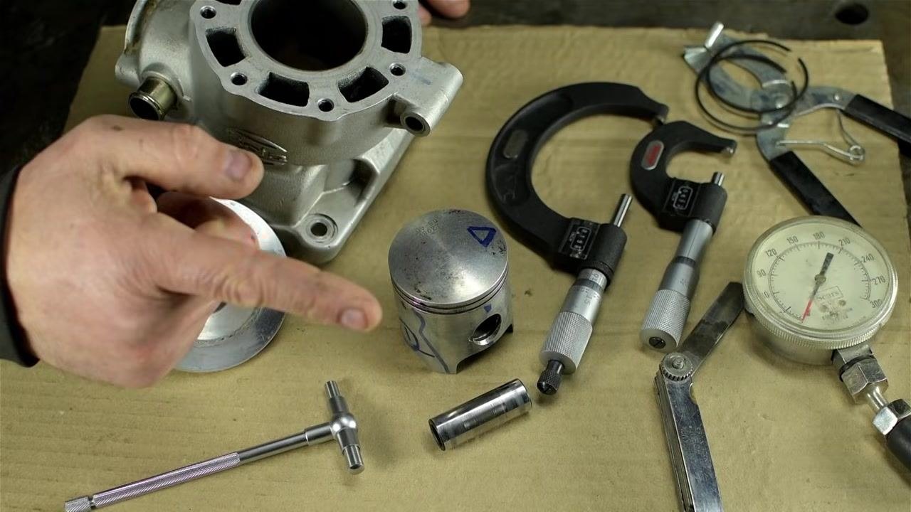
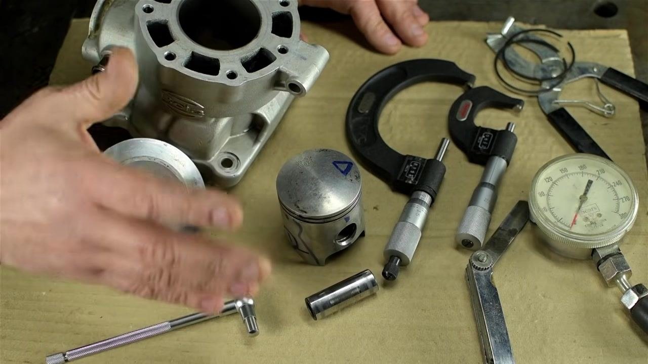
Lay out all necessary components and tools on a clean, flat surface before you begin. Confirm you have the cylinder block, piston, piston pin, telescoping bore gauge, micrometer, dial indicator, feeler gauge set, calipers, and any additional engine parts needed for the job.
Identify and inspect the telescoping bore gauge
Locate the telescoping bore gauge among your tools and check it for cleanliness and smooth operation of the telescopic mechanism. The gauge consists of spring-loaded pins and a locking handle at the back.
Review the bore gauge set
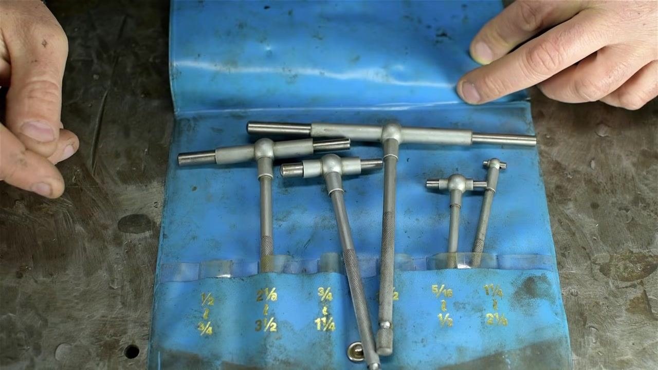
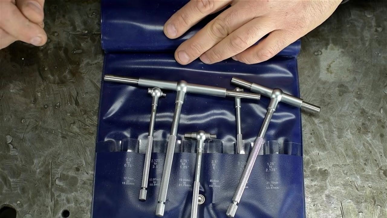
Open the storage pouch or case that holds your set of telescoping bore gauges. Confirm the set includes multiple sizes, typically labeled for different bore diameters (for example 1/2", 3/4", 1"), and inspect each gauge for wear to make sure all pieces are present.
Test the telescoping mechanism
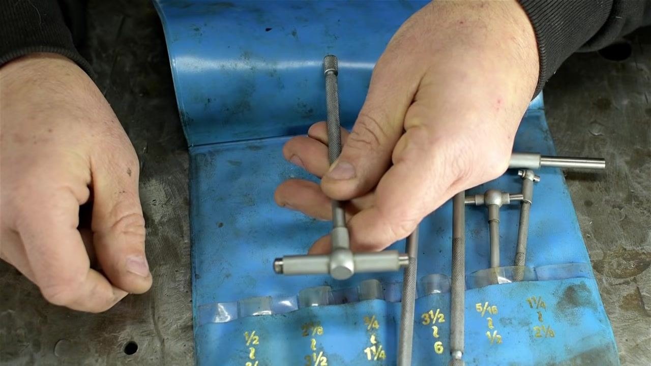
Select a gauge sized appropriately for your cylinder bore. Extend and retract the pins to confirm the spring mechanism moves smoothly, then lock and unlock the handle to verify it holds the pins securely once tightened.
Understand how to use a bore gauge to take a measurement
A telescoping bore gauge transfers the internal dimension of the cylinder bore so it can be read on a separate instrument. Insert the gauge into the bore, expand the pins until they touch the cylinder walls, and lock the handle. Remove the gauge and measure the distance across the pins with a micrometer to determine the bore diameter.
Part 2: Diagnosing and correcting gauge issues
Check the locking mechanism to prevent creep
If the locking mechanism on the telescoping bore gauge is not tightened sufficiently, the anvils (measuring pins) can move or "creep" during measurement. This creep lets your micrometer inadvertently close the pins further as you measure, producing inaccurate readings.
Safety/quality note: Avoid over-tightening the lock. Excessive force is not necessary and can damage the tool or affect measurement repeatability.
Evaluate the smoothness of the gauge
Even reputable brands can have quality issues such as rough or "crunchy" operation. Inspect your bore gauges for smoothness: if the movement is not silky smooth, this hinders accurate measurement. The locking mechanism may still work adequately even when the overall motion feels rough, so check both separately.
Select a gauge to inspect for manufacturing defects
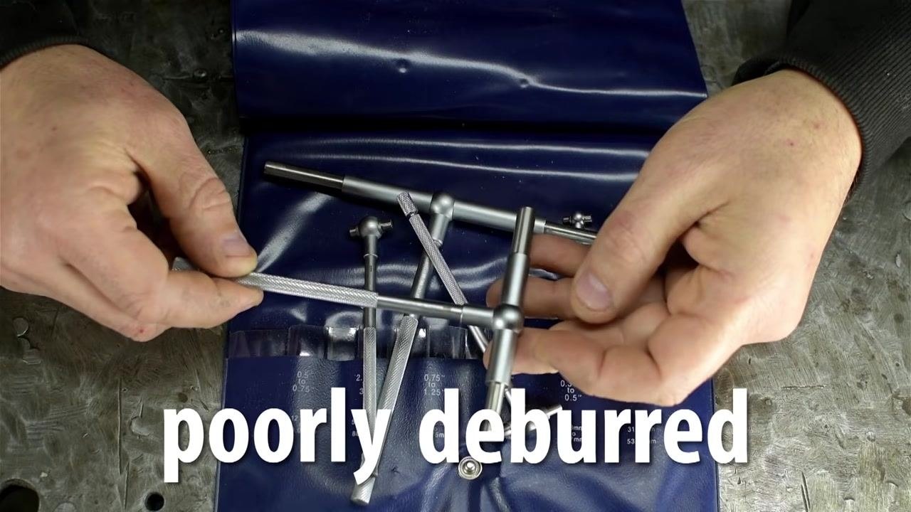
A common issue with some telescoping bore gauges is poor deburring from the factory, which leads to rough or "crunchy" movement. Larger gauges are easier to disassemble and inspect because their parts are easier to see and handle.
Safety note: The internal components are spring-loaded in multiple directions, which increases the risk of losing small parts during disassembly.
Prepare your workspace for disassembly
Clear your workspace of clutter to prevent losing small, spring-loaded parts. Sweep the floor and remove any carpeting, since dropped springs or small components can be difficult to find.
Safety note: Anticipate a high risk of parts flying out unexpectedly, especially given the spring-loaded mechanism.
Position the gauge before disassembly
Place the selected telescoping bore gauge on a clean, flat surface and visually inspect it. Confirm you have a clear working area before proceeding to disassembly.
Part 3: Disassembling the telescoping bore gauge
Loosen the locking knob at the back of the handle
Start disassembly at the back of the gauge by loosening the screw on the handle. On Brown and Sharpe models, the knurled locking knob unthreads from the head; most other sets are likely similar, but if yours differs, look for a spring clip or another retention method.
Safety note: Do not remove the locking knob completely yet. Hold the plungers (anvils) in place while unscrewing, since the two spring-loaded pins are held captive by the knob and can eject unexpectedly if released too quickly.
Secure the gauge in a vise
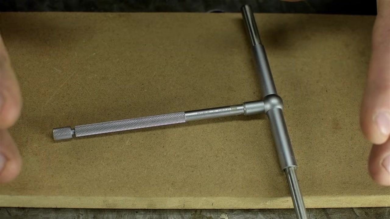
Clamp the gauge in a vise fitted with soft jaws (rubber or urethane) to avoid damaging the tool, positioning it so the handle is accessible but not overly extended. Use care to avoid bending the handle while breaking any thread locker or adhesive present.
Unscrew the locking knob and remove internal components
Carefully finish unscrewing the locking knob while continuing to hold the plungers.
Safety note: One of the spring-loaded parts may eject forcefully once released, so keep your face and eyes clear.
Lay out and inspect the disassembled parts
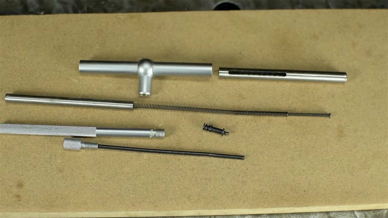
Once the handle is removed, extract the internal components: a spring-loaded retainer pin, a long spring, and a spring guide rod. Lay out all parts on a clean, flat surface for inspection and set aside the small components in a safe place to avoid loss.
Inspect the plunger assembly and drag mechanism
Examine the plungers: they nest inside each other, with a slot in the larger plunger and a key seat in the smaller one. The small retainer pin passes through the slot and into the key seat, which sets the drag on the plungers and locks them in place.
Inspect the plunger slot for burrs
Closely inspect the slot and mating surfaces on the plungers for burrs and roughness. Look for ragged edges or poor deburring on the slot floor and walls, as these cause rough or "crunchy" operation.
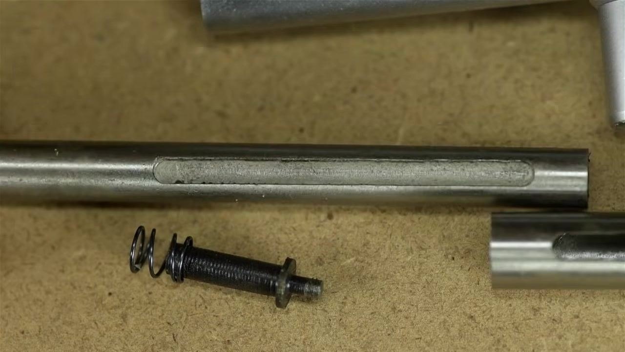
Inspect the mating bore for sharp edges
Check the inside diameter of the mating part for sharp burrs or rough surfaces that can affect drag and smoothness.
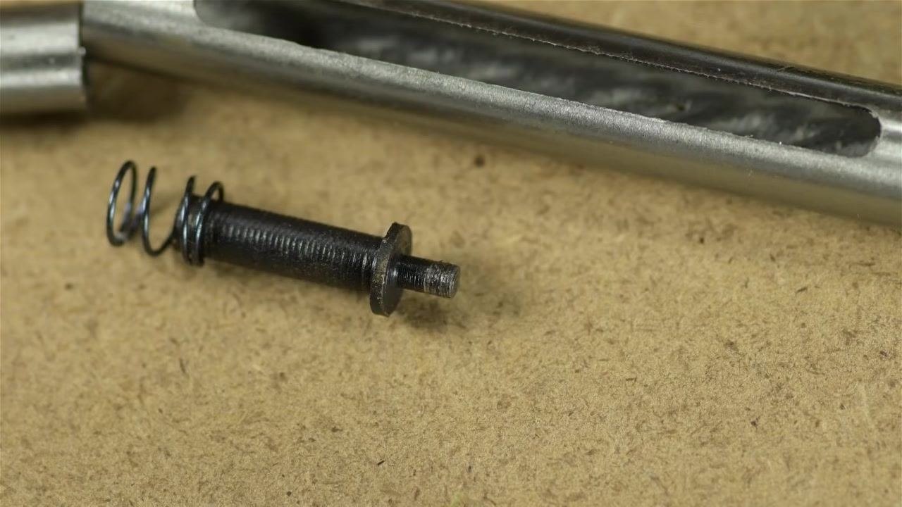
Inspect the retainer pin and spring assembly
Place the retainer pin and spring on a clean, flat work surface for inspection. Check the end of the retainer pin for wear, burrs, or poor surface finish, and inspect the flange and threaded section for damage. Check the spring for deformation, corrosion, or coil irregularities, and review the inside diameter and slot of the plunger body for burrs, rough machining, or debris. Ensure all parts are free of dirt and contaminants before proceeding to deburring.
Part 4: Deburring and finishing the plunger parts
Lay out components for deburring
Place all metal plunger parts, springs, and tools on a clean, flat work surface. Confirm you have abrasive stones, a Dremel stone, and any other required tools ready before starting.
Safety note: Inspect the ends and slots of the metal tubes for sharp edges. The edges of the plungers can be very sharp and hazardous to handle without care.
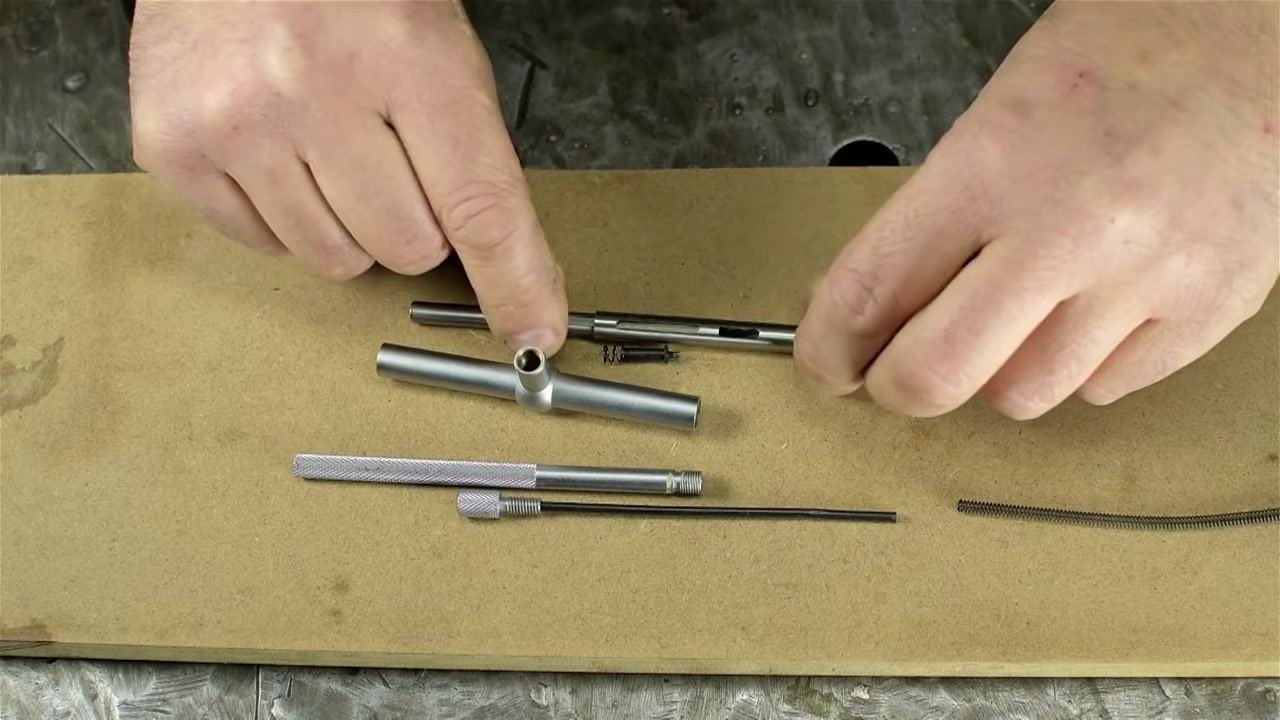
Organize the parts for deburring
Arrange the parts in a logical order for processing, using your fingers to point out and separate each component as needed.
Gather your assortment of abrasive tools before proceeding, including a flat diamond stone (such as a DMT Dia-Sharp), a fine abrasive stick, and a small cylindrical grinding stone for a Dremel tool.
Deburr the edges with a diamond stone
Use a flat abrasive stone to gently smooth the sharp edges of the metal tubes. Hold the tube steady and run the stone along the edge, applying light, even pressure.
Break the edge on the outer diameter
Use a finer abrasive stone (400 grit) to further break and smooth the outer edge of the tube, rotating the tube as you work to ensure all edges are evenly deburred.
Deburr the inside with a Dremel stone
Use a small cylindrical stone intended for a Dremel tool (often used for sharpening chainsaws) to reach and deburr the inside edges of the larger plunger tube. Insert the stone into the tube and gently rotate to remove internal burrs.
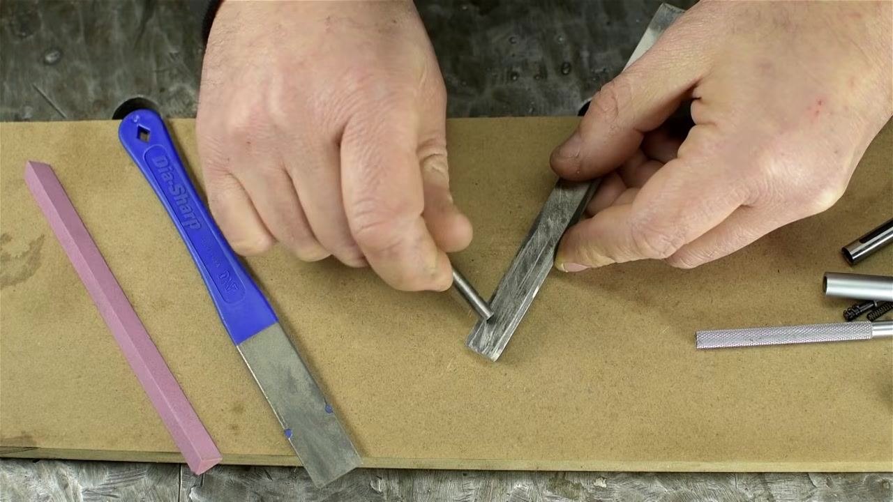
Continue deburring until the edges are smooth
Repeat the deburring process on all sharp parts until the edges feel smooth to the touch. Continue deburring each part until you are satisfied with the result.
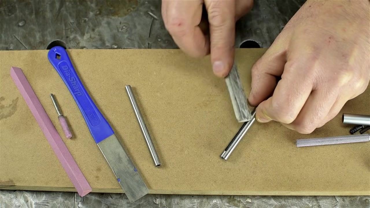
Make a final deburring pass
Make a final pass with the abrasive stone on all edges to ensure no sharpness remains, and inspect each part both visually and by touch for any remaining burrs.
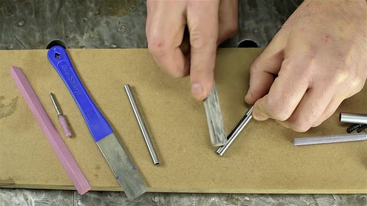
Clean and lightly oil the parts
Once all parts are deburred and clean, apply a very light oiling to the metal surfaces. Use a clean cloth or your fingers to spread a thin layer of oil, which helps prevent rust and ensures smooth operation.
Assemble the parts and inspect the fit
Begin assembling the parts to check fit and smoothness. If any part still feels rough or catches, repeat the deburring process on that part as needed until the assembly moves freely.
Verification and summary
- Confirm each deburred part is smooth to the touch with no remaining sharp edges or burrs.
- Confirm the reassembled plunger and locking mechanism move freely without creep or catching.
- Confirm all tools (diamond stone, abrasive stick, Dremel stone, gauges, and fasteners) are accounted for and returned to storage.
- Confirm the work surface is wiped clean of metal filings and abrasive residue.
Once verified, your telescoping bore gauge is ready for accurate cylinder bore measurement: insert it into the bore, expand and lock the pins against the cylinder walls, remove it, and read the pin span with a micrometer to obtain the bore diameter.
Tips: - Always handle sharp metal parts with care to avoid injury. - Wear appropriate personal protective equipment, such as gloves and safety glasses, when working with abrasive tools or spring-loaded components. - Take the time needed to fully deburr all edges to ensure safe, smooth operation of the assembled tool.
Generation details: cost, quality tiers
Docsie billed 3,500 credits ($2.45) to analyze this 7-minute video at standard quality. The rewrite, template fill and Word/PDF exports were included. The same video at each quality tier:
| Quality | Frames sampled | Credits | Approx. cost |
|---|---|---|---|
| Draft | every 16-30 s | 1,750 | $1.22 |
| Standard (this guide) | every 8-15 s | 3,500 | $2.45 |
| Detailed | every 4-7 s | 7,000 | $4.90 |
| Ultra | every 1-3 s | 14,000 | $9.80 |
Credits priced at $0.70 per 1,000; plans include a monthly allowance. Enterprise customers on on-premise or bring-your-own-model deployments run this on their own inference and pay no per-video credits.
Generated by Docsie Video-to-Docs on 2026-09-20 from a 6-minute video. Screenshots are frames from the source video and belong to their creator, This Old Tony, whose original is embedded above. If you own this video and want the guide removed or credited differently, contact us and we will act within one business day.