
How to Test an Hvac Capacitor
This standard operating procedure explains how to test an HVAC capacitor safely and accurately. It covers the role capacitors play in single-phase motors, how to identify capacitor types and ratings, and the step-by-step process for discharging and testing both single and dual run capacitors with a multimeter. Following this procedure helps you confirm whether a capacitor is functioning correctly or needs replacement, reducing the risk of motor failure and electrical hazards.
Video: How to Test an HVAC Motor Capacitor | Spec. Sense by AMRE Supply (2019). All credit for the demonstration goes to the creator; watch the original on YouTube. The written guide below was generated from this video by Docsie. Creator? Request a change or removal.
This standard operating procedure explains how to test an HVAC capacitor safely and accurately. It covers the role capacitors play in single-phase motors, how to identify capacitor types and ratings, and the step-by-step process for discharging and testing both single and dual run capacitors with a multimeter. Following this procedure helps you confirm whether a capacitor is functioning correctly or needs replacement, reducing the risk of motor failure and electrical hazards.
Purpose
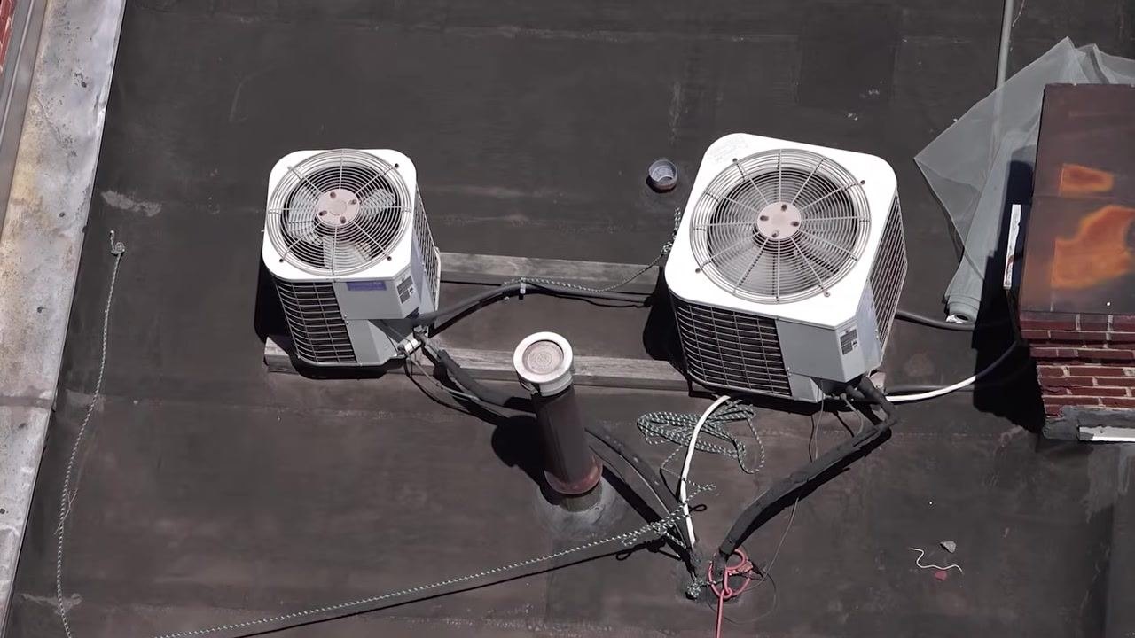
Capacitors are essential components in many single-phase motors, including furnace blowers, air conditioner fans, compressors, and pumps. This SOP provides a reliable method to test these capacitors so you can confirm their condition before returning equipment to service.
Scope
This procedure applies to single run capacitors and dual run capacitors found in common HVAC equipment. It includes safe discharge procedures, capacitance testing, and continuity testing for shorts to ground.
Required equipment and PPE
- Multimeter with capacitance (μF) and ohms (Ω) settings
- Screwdriver with an insulated handle (or a resistor) for discharging capacitors
- Replacement capacitor matching the correct capacitance and voltage rating, if needed
Understanding capacitor function
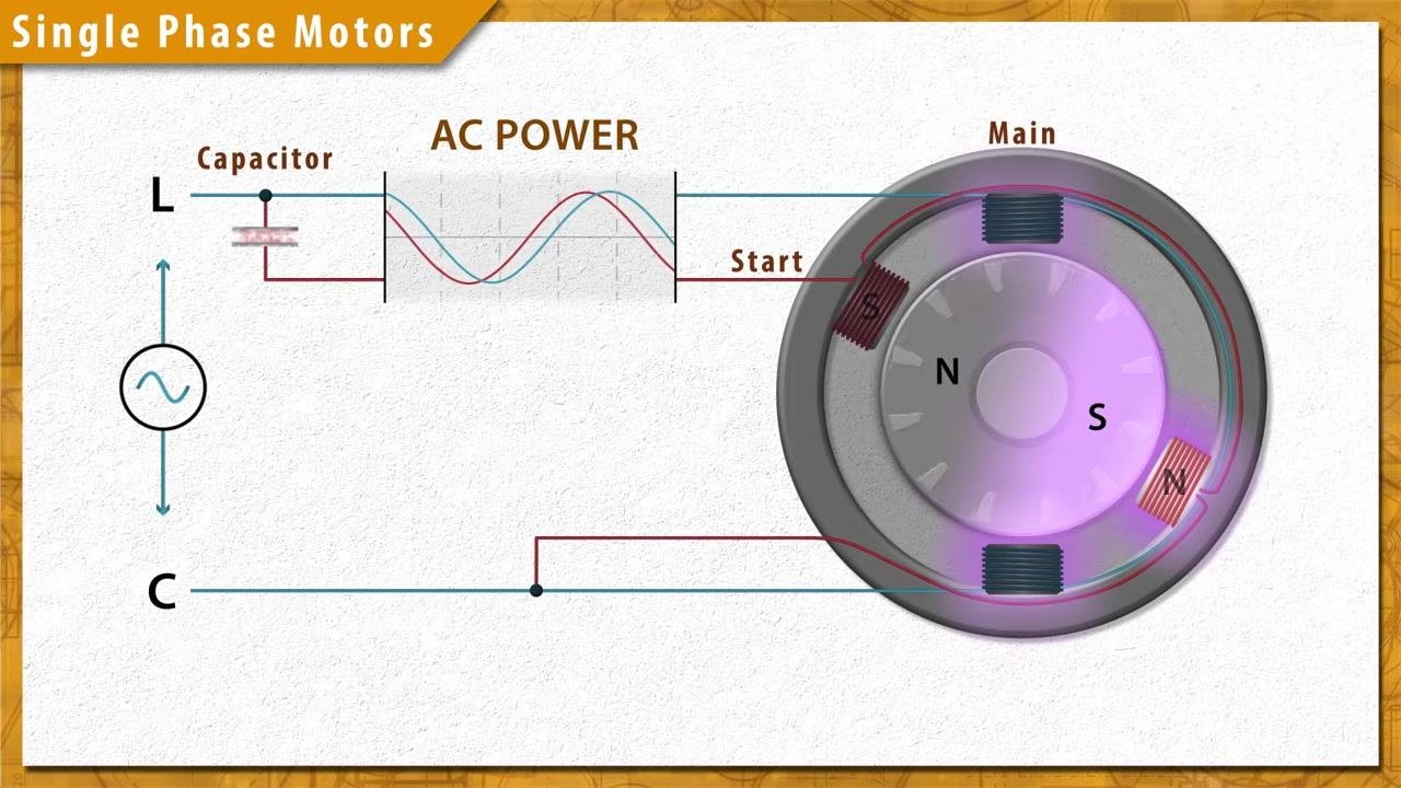
A capacitor stores electrical energy. As an electrical charge builds and releases between the dielectric plates, the voltage lags behind the charging current. This lag creates a magnetic phase shift in the start winding, which provides the torque needed to turn the rotor.
Recognizing symptoms of capacitor failure
Watch for the following signs that a capacitor may have failed:
- The motor does not start or starts slowly
- The capacitor shows visible bulging or leaking
- Some failures are internal and produce no visible external signs
Always ensure the capacitor is safely discharged before testing. Use a multimeter to test the capacitance, as described later in this procedure.
Capacitor ratings and selection
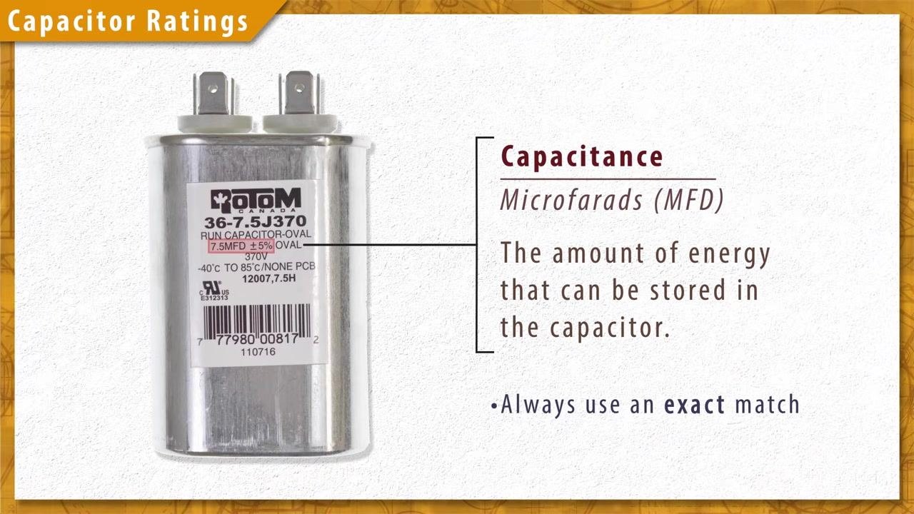
Every capacitor has two main ratings printed on its label:
- Capacitance (expressed in microfarads, MFD or µF): indicates how much energy the capacitor can store
- Voltage rating (V): indicates the maximum voltage the capacitor can be exposed to
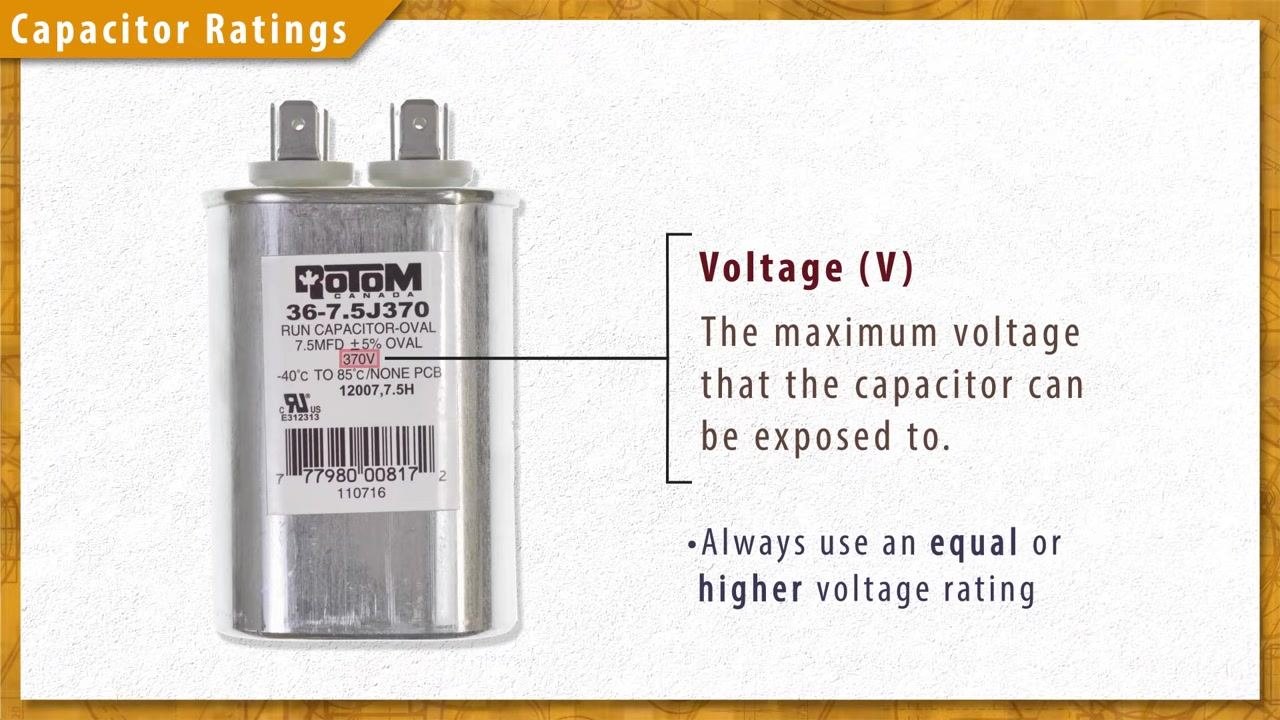
When selecting a replacement capacitor, always use one with an equal or higher voltage rating than the original. Never install a capacitor with a lower voltage rating, as this can cause capacitor failure.
The capacitance value determines the energy storage capability of the capacitor, which is critical for correct motor operation.
Identifying capacitor types
Start capacitors
Start capacitors have high capacitance, typically ranging from 40 to 300 microfarads (MFD). They are used only briefly during the startup sequence in capacitor start motors.
Run capacitors
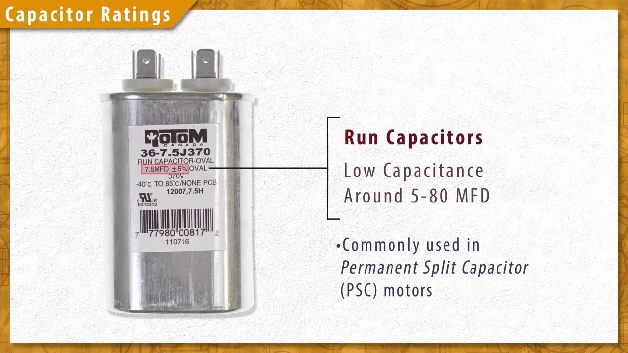
Run capacitors have lower capacitance, generally between 5 and 80 microfarads (MFD). They remain permanently wired into the circuit and are used in permanent split capacitor (PSC) motors.
Dual run capacitors
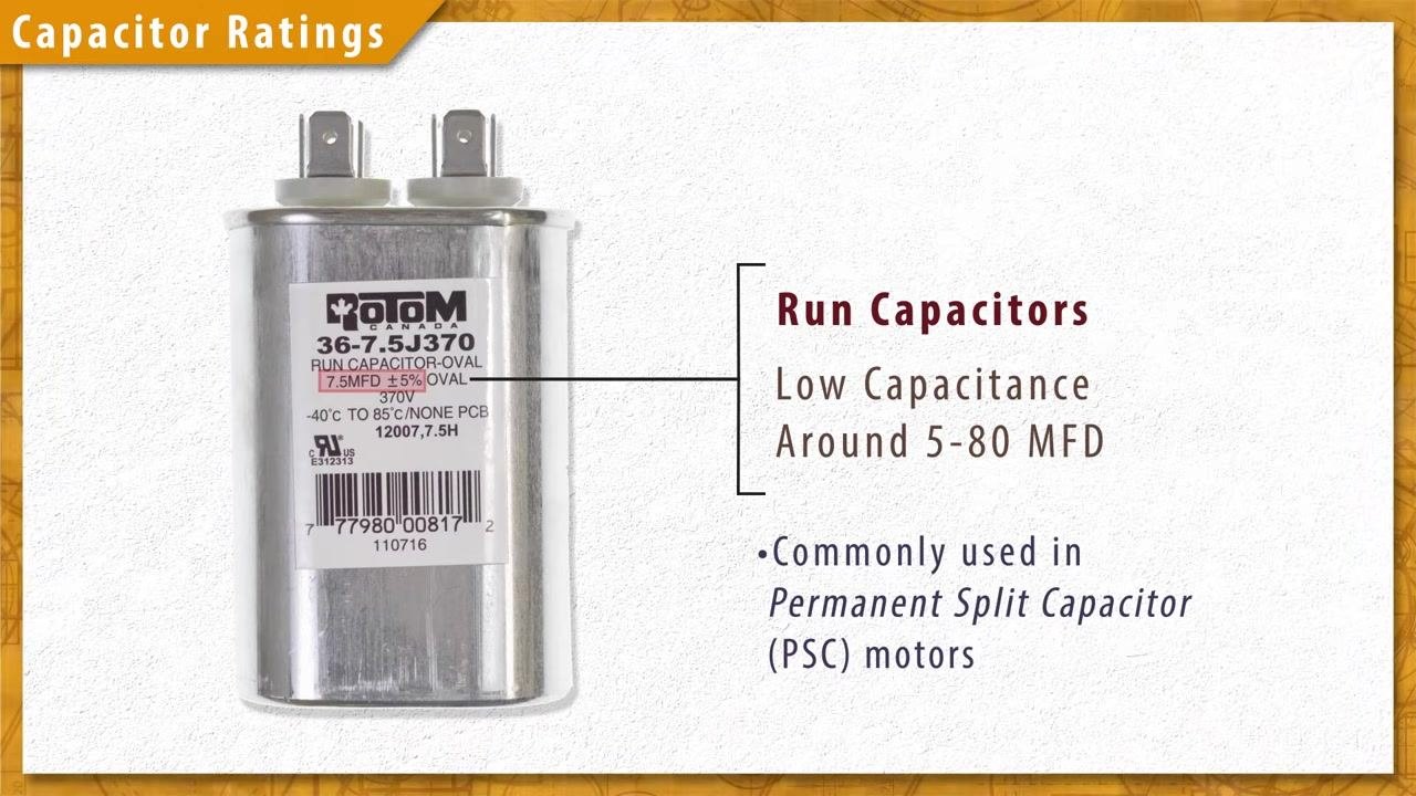
Dual run capacitors support two electric motors, such as the compressor and blower fan in an air conditioning unit. They have three terminals labeled Common (C), Fan, and Herm (hermetically sealed compressor), along with two microfarad ratings — a higher rating for the compressor and a lower rating for the fan.
Safety precautions before handling capacitors
Before accessing any capacitor, disconnect the power and gas supply to the equipment.
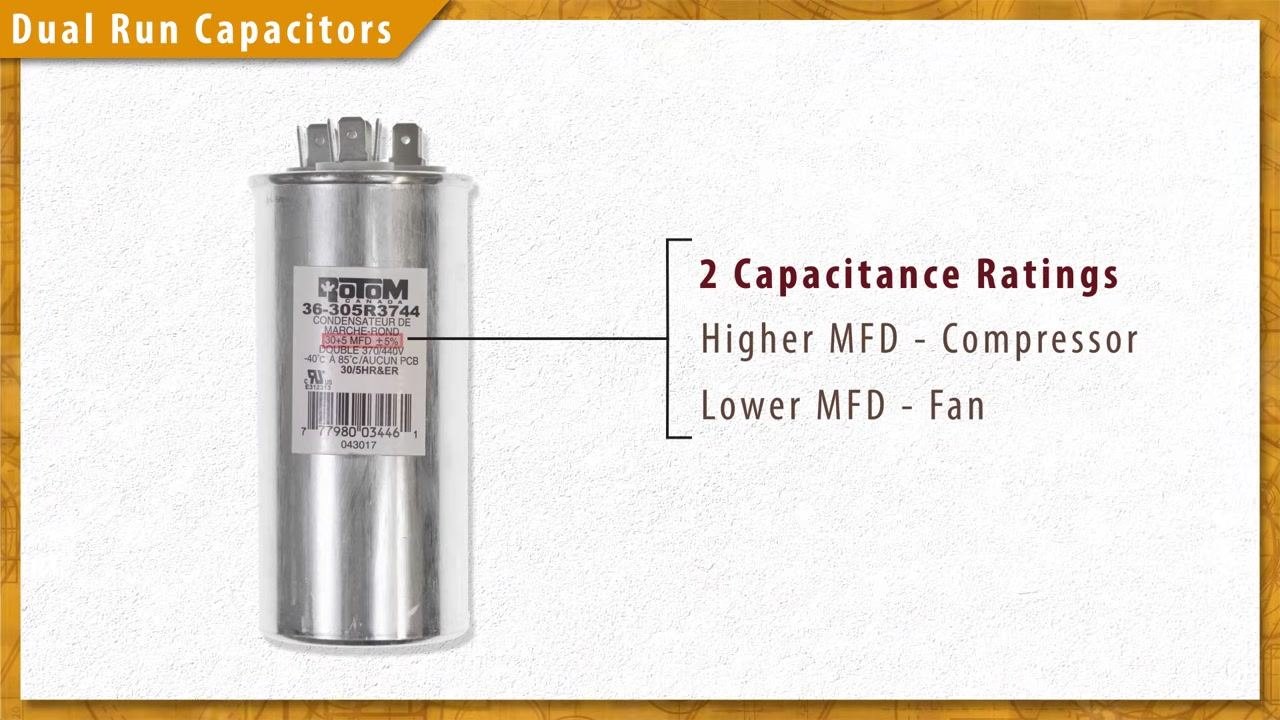
Capacitors can retain a charge even after the power is switched off. Always assume a capacitor is charged, since contact with a charged capacitor carries a risk of serious electrical shock.
Discharging a capacitor safely
Before testing, you must discharge any stored electrical energy in the capacitor. Place a resistor or a screwdriver with an insulated handle across the terminals to short out and discharge the capacitor.
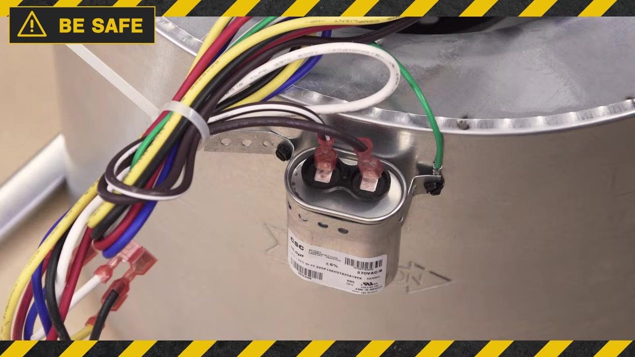
To discharge a single run capacitor, touch both terminals at the same time with a screwdriver that has an insulated handle. This shorts the terminals and safely discharges the capacitor.
For a dual run capacitor, discharge both sides by touching the screwdriver across the Perm (permanent) and Common terminals. This discharges both capacitors contained within the dual run unit. Always observe safety precautions to avoid electrical shock.
Testing a single run capacitor with a multimeter
Set your multimeter to the capacitance (μF) testing function. Confirm the capacitor is fully discharged before proceeding.
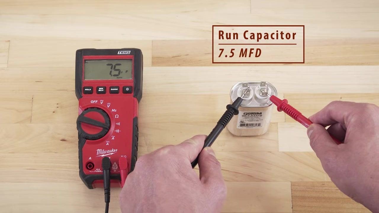
Touch one probe to each terminal of the capacitor and observe the reading on the multimeter display.
The multimeter should display a value close to the capacitor's rated capacitance, for example 7.5 MFD on a run capacitor rated at that value. If the reading falls within ±5% of the rated value, the capacitor is good.
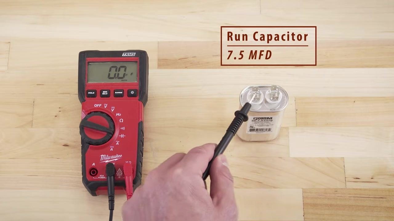
If the multimeter shows 0.0 μF or a value far from the rated capacitance, the capacitor has failed and should be replaced.
Testing a dual run capacitor with a multimeter
Test each section of the dual run capacitor separately:
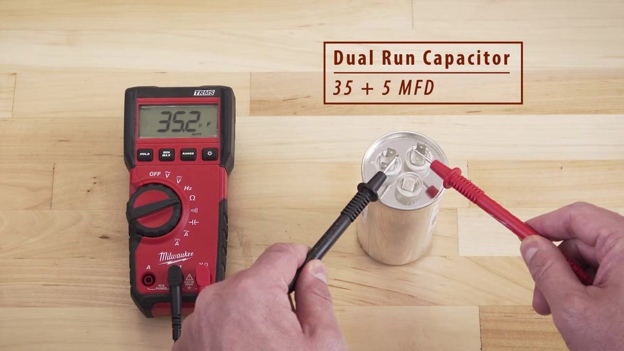
- Test from Herm (compressor) to Common and note the reading. It should match the higher MFD rating, for example 35 MFD.
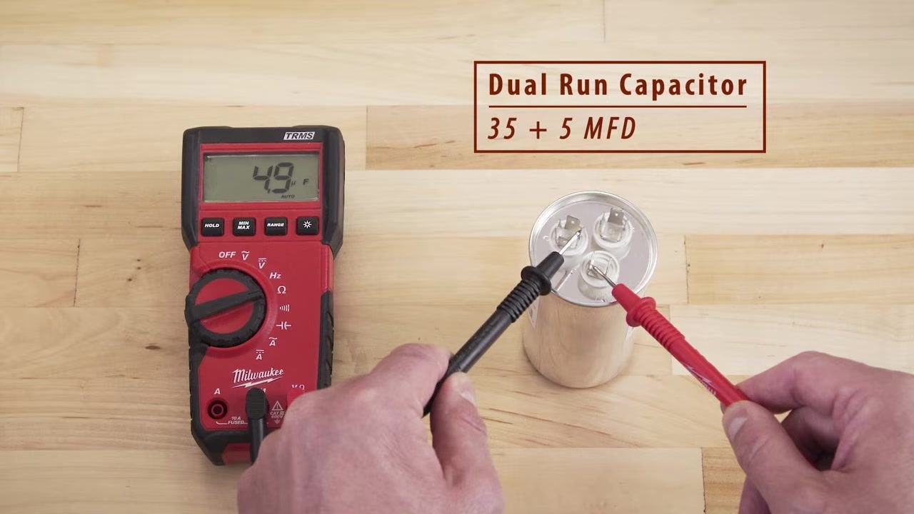
- Test from Fan to Common and note the reading. It should match the lower MFD rating, for example 5 MFD.
Both readings should be close to their respective rated values.
Checking for a short to ground
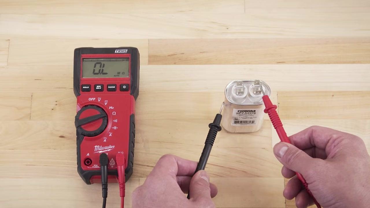
Set the multimeter to the ohms (Ω) setting. Touch one probe to each terminal and the other probe to the metal housing of the capacitor. The multimeter should display "OL" (open loop), indicating no continuity.
If any resistance is detected during this test, the capacitor is shorted to ground and must be replaced.
Verification
Confirm that all capacitance readings fall within tolerance of the rated values and that no shorts to ground were detected. If both conditions are met, the capacitor is safe to use.
If any reading is significantly outside the rated tolerance, or if a short to ground is present, replace the capacitor before returning the equipment to service.
Getting additional help
If you require further assistance or have questions about testing or replacing motor capacitors, call or visit an AMRE Supply location. Knowledgeable staff can provide expert advice and support.
Safety and responsibility disclaimer
This procedure is intended to inform and educate on product knowledge, maintenance, and general project guidance. The information provided is accurate to the best of available knowledge; however, materials, codes, and regulations may change, and errors or omissions are possible.
- You are responsible for complying with all applicable codes, rules, laws, and regulations.
- Always follow best safety practices during any project.
- Contact a licensed professional if you have any doubts about the safety of your project.

What's next
Once you have confirmed the capacitor's condition, either return the tested capacitor to service or install a replacement matching the correct capacitance and voltage rating. Always disconnect power and discharge capacitors before performing any further electrical work.
Generation details: cost, quality tiers
Docsie billed 3,000 credits ($2.10) to analyze this 6-minute video at standard quality. The rewrite, template fill and Word/PDF exports were included. The same video at each quality tier:
| Quality | Frames sampled | Credits | Approx. cost |
|---|---|---|---|
| Draft | every 16-30 s | 1,500 | $1.05 |
| Standard (this guide) | every 8-15 s | 3,000 | $2.10 |
| Detailed | every 4-7 s | 6,000 | $4.20 |
| Ultra | every 1-3 s | 12,000 | $8.40 |
Credits priced at $0.70 per 1,000; plans include a monthly allowance. Enterprise customers on on-premise or bring-your-own-model deployments run this on their own inference and pay no per-video credits.
Generated by Docsie Video-to-Docs on 2026-09-20 from a 5-minute video. Screenshots are frames from the source video and belong to their creator, AMRE Supply, whose original is embedded above. If you own this video and want the guide removed or credited differently, contact us and we will act within one business day.