
How to Test a Water Heater Thermostat
This SOP explains how to test a water heater thermostat in an electric water heater equipped with upper and lower heating elements. Following these steps will help you determine whether a thermostat has failed and needs replacement, using a simple continuity test with a multimeter.
Video: Water Heater Not Heating? Thermostat Testing by RepairClinic.com (2017). All credit for the demonstration goes to the creator; watch the original on YouTube. The written guide below was generated from this video by Docsie. Creator? Request a change or removal.
This SOP explains how to test a water heater thermostat in an electric water heater equipped with upper and lower heating elements. Following these steps will help you determine whether a thermostat has failed and needs replacement, using a simple continuity test with a multimeter.
Purpose
This procedure describes how to test a water heater thermostat for continuity, allowing you to confirm whether the component is functioning correctly or must be replaced.
Scope
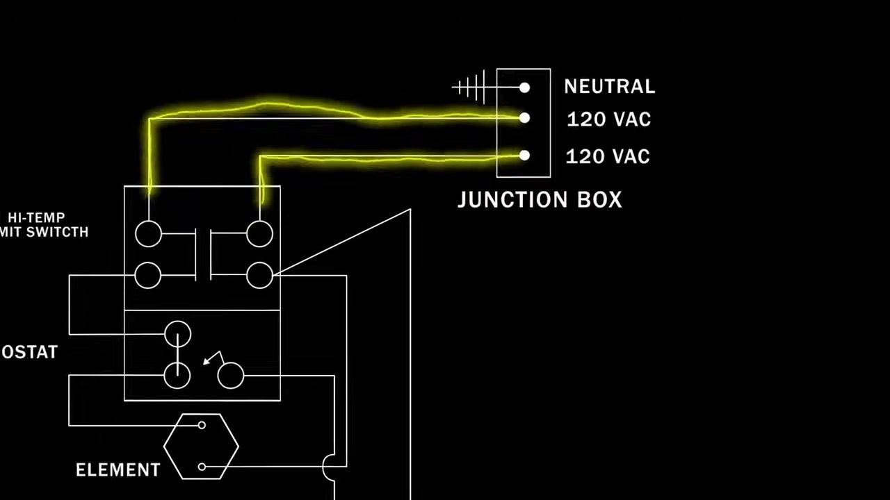
This procedure applies to electric water heaters with two heating elements, each controlled by its own thermostat (an upper thermostat and a lower thermostat). The thermostats regulate water temperature by opening and closing contacts, which allows voltage to flow to the heating elements. Only one element is powered at a time, and the cycling frequency depends on heating demand.
When to perform this test
If you suspect a thermostat is defective, test it for continuity (a continuous electrical path). A thermostat that does not show continuity when it should has failed and must be replaced.
Required equipment
- A multimeter (analog or digital)
Safety precautions
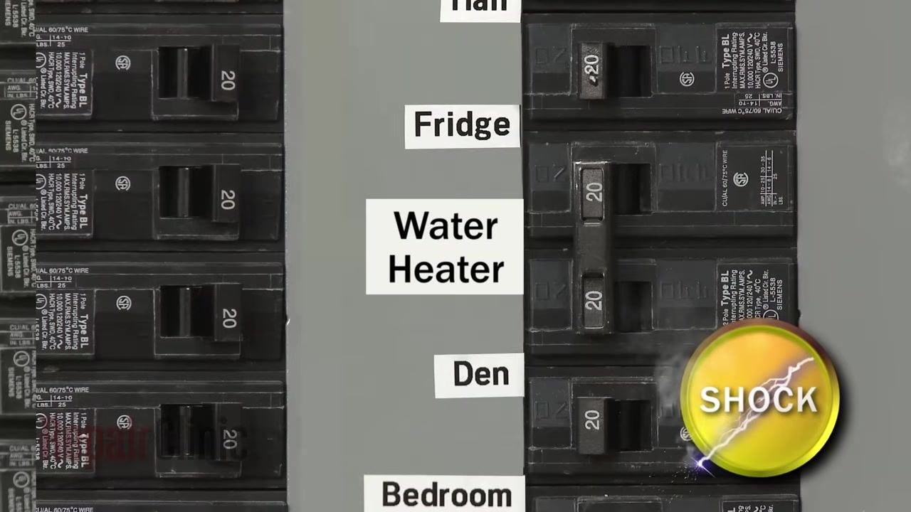
- Always shut off power to the water heater at the circuit breaker before accessing internal components.
- Confirm the correct breaker is switched OFF before proceeding.
- Note the position and orientation of all wires before disconnecting them, so they can be reconnected correctly afterward.
Step-by-step procedure
Step 1: Set up your multimeter
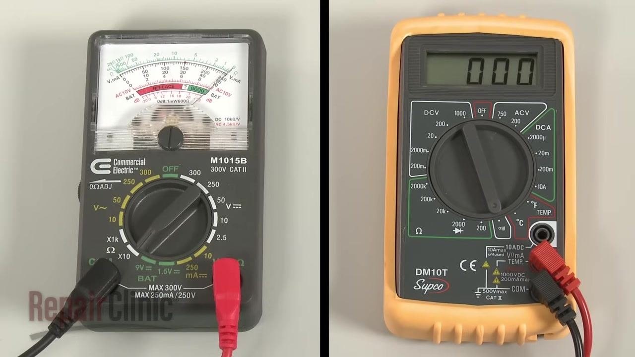
If you are using an analog multimeter, rotate the range selection dial to the lowest setting for ohms of resistance (Ω), then calibrate the meter by pinching the leads together and adjusting the needle to read zero.
If you are using a digital multimeter, rotate the dial to the lowest setting for ohms of resistance, or to resistance with tone if that option is available.
Step 2: Shut off power at the circuit breaker
Locate the breaker labeled Water Heater on your electrical panel and switch it to the OFF position. This step is essential to avoid electrical shock while testing.
Step 3: Access the thermostat
Remove the upper access panel on the water heater. Move the insulation out of the way and detach the protective cover to expose the thermostat and wiring.
Step 4: Perform an initial continuity check
Place the multimeter probes on the thermostat terminals. If the multimeter shows no continuity (an open circuit), the thermostat is defective.
If continuity is present, the thermostat is functioning. If there is no continuity, the thermostat must be replaced.
Testing the upper thermostat
Step 5: Check the reset button
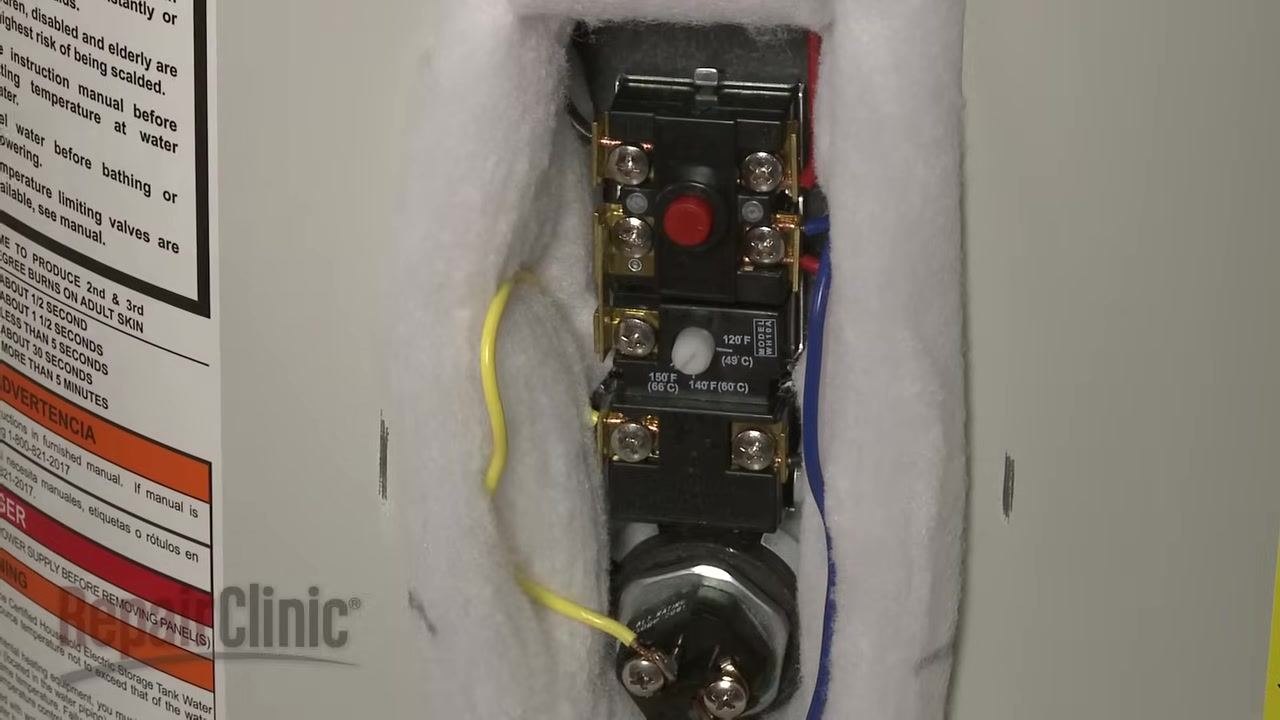
Locate the red reset button on the upper thermostat. The reset button may trip if the water in the tank overheats. Possible causes for tripping include:
- Thermostat contacts fusing closed
- Thermostat being out of calibration
- A shorted heating element
Reset the button if necessary by pressing it.
Step 6: Disconnect the power wires
Carefully observe and note the orientation and position of all power wires connected to the thermostat, then disconnect them to isolate the thermostat from the circuit.
Step 7: Test the reset portion of the thermostat
Touch one multimeter lead to the left-side terminal on the reset portion of the thermostat, and touch the second lead to the other left-side terminal. The meter should indicate close to 0 ohms of resistance if the component has continuity. On an analog meter, the needle should move; on a digital meter, the display should change to a low value.
If the analog meter needle does not move at all, or the digital display does not change significantly, the thermostat has no continuity and is defective. If continuity is present, the thermostat is functioning.
Repeat this test on the right-side terminals of the reset portion.
Step 8: Test the lower portion of the upper thermostat
Touch one lead to the common terminal and the second lead to the upper heating element terminal. If the water temperature is below the designated setting, the meter should indicate close to zero ohms of resistance.
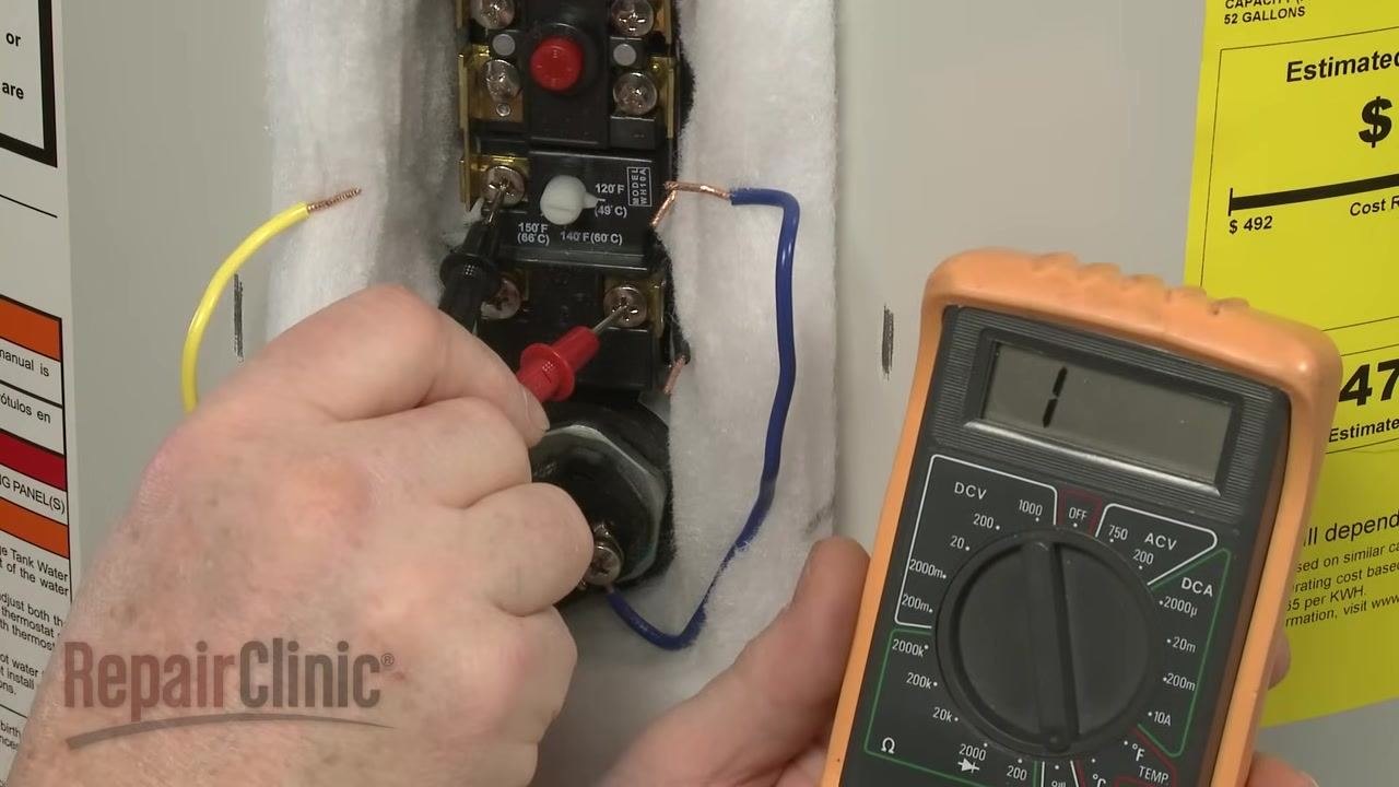
Next, move the second lead to the lower heating element terminal. The meter should indicate no continuity if the water temperature is below the designated setting.
If the water temperature is above the designated setting, the results will be reversed: continuity at the lower terminal and none at the upper terminal.
Testing the lower thermostat
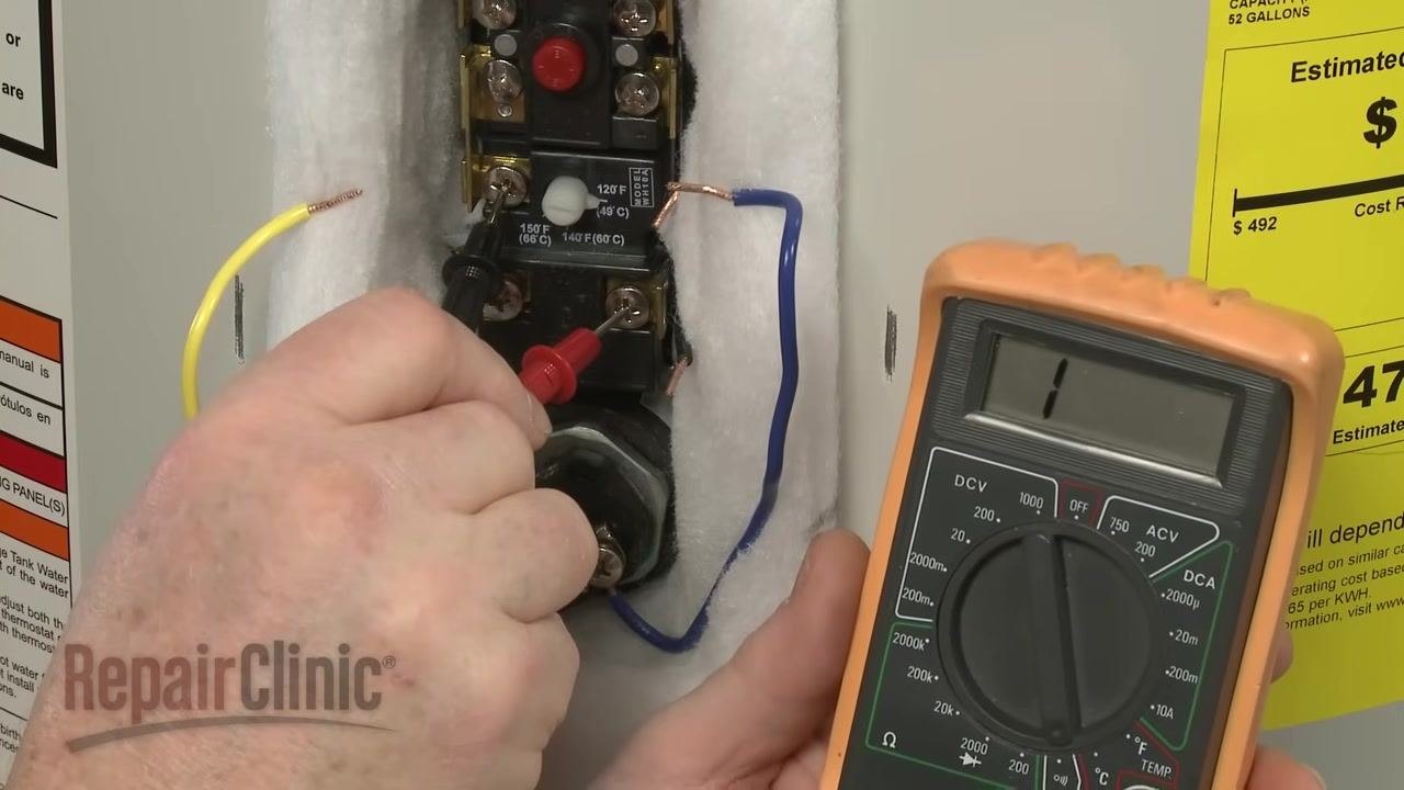
Step 9: Verify lower element terminal continuity
Confirm that the lower element terminal shows continuity (close to 0 ohms) and the upper element terminal does not, if the water temperature is below the designated setting. If the water temperature is above the designated setting, the meter should indicate no continuity at the lower element terminal. An opposite reading indicates a defective thermostat that must be replaced.
Step 10: Prepare to test the lower thermostat
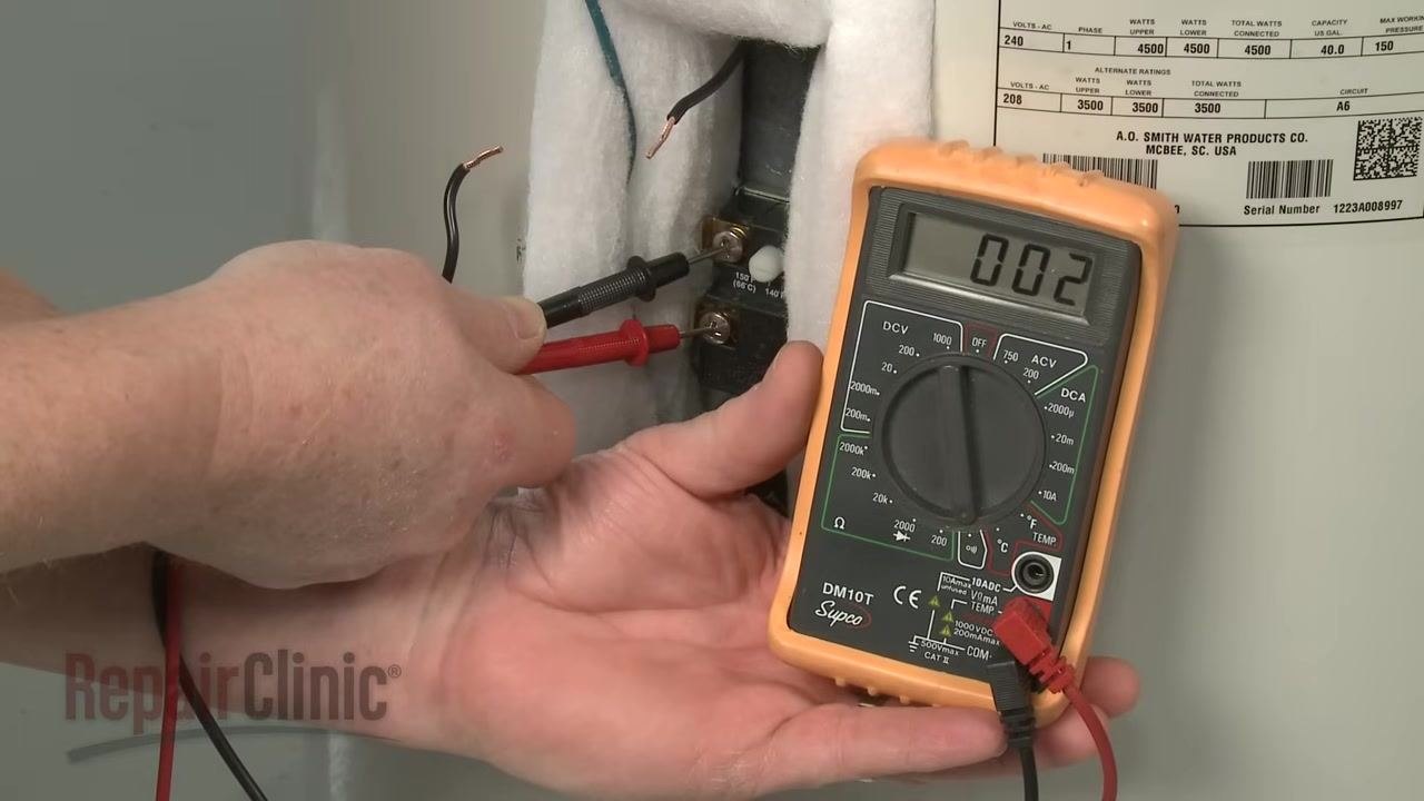
Ensure all power wires are disconnected from the lower thermostat to isolate it from the circuit. Position the multimeter probes so that one touches each terminal of the lower thermostat, keeping insulation pulled aside and wires clearly visible.
Step 11: Perform the continuity test on the lower thermostat
Touch one multimeter lead to one terminal of the lower thermostat and the second lead to the other terminal. Observe the multimeter display for the resistance reading.
Step 12: Interpret the results
If the water temperature is below the designated setting, the meter should display close to 0 ohms (for example, 0.2 ohms), indicating continuity and a functioning thermostat.
If the water temperature is above the designated setting, the meter should display "1" or "OL" (open loop), indicating no continuity.
If you receive the opposite reading (no continuity when there should be, or continuity when there should not be), the thermostat is defective and must be replaced.
Verification and reassembly
Once testing is complete, reconnect all wires to their original positions as noted in Step 6. Replace any insulation and covers that were removed during the process.
Summary
By following this procedure, you can accurately test the upper and lower thermostats in your electric water heater and determine whether replacement is necessary. Always ensure the power is off before accessing electrical components, and carefully note wire positions to guarantee correct reassembly.
What's next
If either thermostat fails the continuity test, obtain a replacement thermostat and install it in place of the defective unit, using the wire positions noted during testing to guide reassembly.

Generation details: cost, quality tiers
Docsie billed 2,500 credits ($1.75) to analyze this 5-minute video at standard quality. The rewrite, template fill and Word/PDF exports were included. The same video at each quality tier:
| Quality | Frames sampled | Credits | Approx. cost |
|---|---|---|---|
| Draft | every 16-30 s | 1,250 | $0.88 |
| Standard (this guide) | every 8-15 s | 2,500 | $1.75 |
| Detailed | every 4-7 s | 5,000 | $3.50 |
| Ultra | every 1-3 s | 10,000 | $7.00 |
Credits priced at $0.70 per 1,000; plans include a monthly allowance. Enterprise customers on on-premise or bring-your-own-model deployments run this on their own inference and pay no per-video credits.
Generated by Docsie Video-to-Docs on 2026-09-20 from a 4-minute video. Screenshots are frames from the source video and belong to their creator, RepairClinic.com, whose original is embedded above. If you own this video and want the guide removed or credited differently, contact us and we will act within one business day.