
How to Test a Refrigerator Compressor
This guide explains how to test a refrigerator compressor using a digital multimeter, so you can determine whether the compressor windings are in good condition before replacing any parts. It also covers how to test the compressor's relay and start capacitor if the compressor does not run after passing a resistance test. Following these steps helps you confirm whether a refrigerator or freezer that is not cooling has a faulty compressor, a bad relay, or a bad start capacitor.
Video: How to Test the Compressor on your Refrigerator by Bill Newberry (2013). All credit for the demonstration goes to the creator; watch the original on YouTube. The written guide below was generated from this video by Docsie. Creator? Request a change or removal.
This guide explains how to test a refrigerator compressor using a digital multimeter, so you can determine whether the compressor windings are in good condition before replacing any parts. It also covers how to test the compressor's relay and start capacitor if the compressor does not run after passing a resistance test. Following these steps helps you confirm whether a refrigerator or freezer that is not cooling has a faulty compressor, a bad relay, or a bad start capacitor.
Scope
This procedure applies to standard AC compressors found in most top freezer and side-by-side refrigerators. It also includes guidance on verifying compressor operation with a relay and power cord, and on testing or replacing the relay and start capacitor. Variable speed compressors are identified in this guide but are tested differently and are not covered in detail here.
Required equipment
- A digital multimeter with true RMS capability (a Milwaukee TRMS clamp meter is used in this procedure)
- Red and black test leads for the multimeter
- The refrigerator compressor you want to test
- A relay and power cord, used to verify compressor operation
- A three-in-one start capacitor (optional replacement part, if the relay is faulty)
- A stable, non-conductive work surface
Safety note: Always disconnect the compressor and refrigerator from power before taking resistance readings. Only reconnect power when you are specifically verifying operation.
Identifying your compressor type
Before testing, confirm which type of compressor you have, since the test procedure differs by type.
- If the compressor has a relay and a capacitor plugged into its side (a small component), it is a standard AC compressor.
- If a large box — three to four times the size of a standard relay/capacitor — is attached to the compressor, it is likely a variable speed compressor, which requires a different test method.
Locating and preparing the compressor terminals
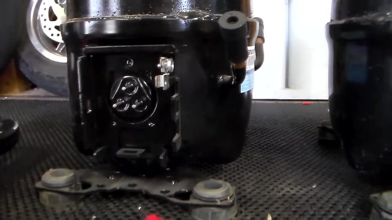
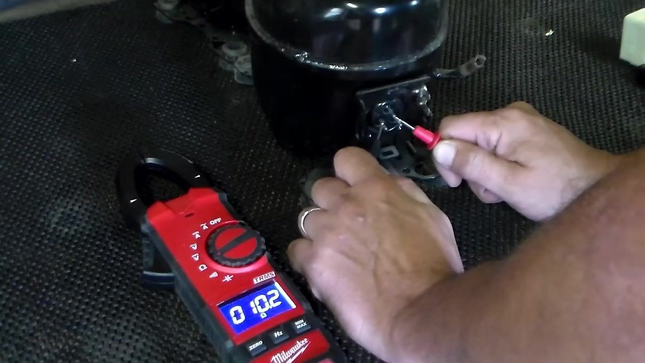
Step 1: Locate the compressor terminals. Find the three small terminals on the side of the compressor; these are the points where you will take your ohm readings. Remove any covers or connectors as needed to expose the terminals fully.
Step 2: Review the compressor connections. A standard compressor has a relay and capacitor assembly that resembles a small plug-in module. A variable speed compressor instead has a much larger control box attached.
Setting up the multimeter
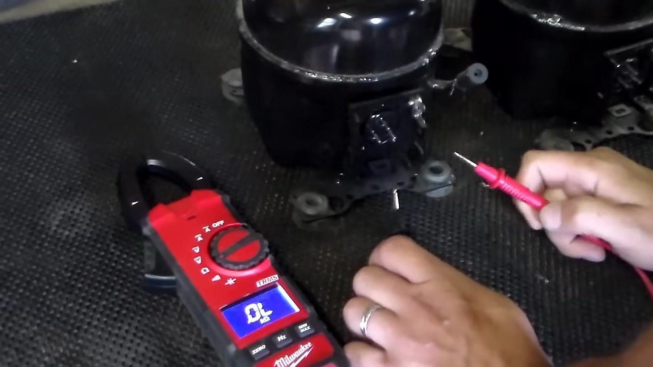
Step 3: Set the multimeter to ohms. Turn the multimeter dial to the Ohms (Ω) setting to measure resistance. Confirm the display reads OL (open loop) before you begin testing, which indicates no connection between the leads.
Step 4: Prepare for testing. Place the compressor on a stable, non-conductive surface. Hold the test leads near the compressor terminals so you are ready to take measurements.
Testing resistance on a new compressor
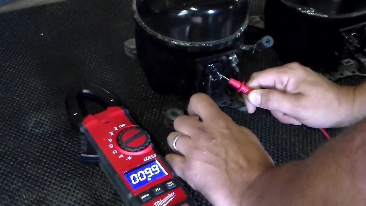
Step 5: Test the resistance across the bottom two pins. Place one probe on each of the two bottom terminals, which form the base of a triangle. On a brand-new compressor, expect a reading of approximately 10 ohms.
Step 6: Test the resistance from the left bottom pin to the top pin. Move one probe to the left bottom terminal and the other to the top terminal. Expect a reading of about 6 ohms.
Step 7: Test the resistance from the top pin to the right bottom pin. Place one probe on the top terminal and the other on the right bottom terminal. Expect a reading of about 4 ohms; actual readings may vary slightly.
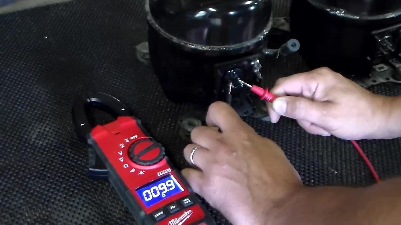
Step 8: Verify the multimeter with the probes separated. Touch the probes together away from the compressor terminals, or hold them apart, to confirm the multimeter returns to OL. This confirms the meter is functioning correctly and not producing false readings.
Confirming consistent readings
Step 9: Re-test the bottom two pins. Repeat the measurement across the bottom two terminals to confirm a reading of approximately 10 ohms.
Step 10: Re-test from the top pin to the bottom left pin. Repeat the measurement from the top terminal to the bottom left terminal to confirm a reading of approximately 6 ohms.
Interpreting the results: If your readings are consistently near 10, 6, and 4 ohms on a new compressor, the windings are likely in good condition. If a reading behaves as though the probes are touching each other (very low resistance or a short), the compressor is likely faulty and should be replaced. This test is especially useful when the refrigerator is not cooling, the freezer fan is running, but the compressor itself is not operating.
Safety note: Always confirm the compressor is disconnected from power before performing resistance tests. If your readings differ significantly from the expected values, consult the compressor's specifications or consider replacing the unit.
Testing resistance on a used compressor
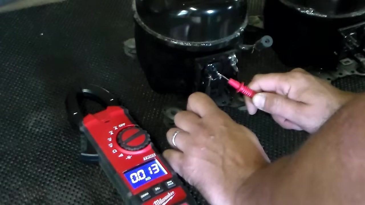
Step 11: Test resistance across the bottom two terminals. Place the probes across the bottom two terminals of the used compressor. Expect a reading close to 10 ohms.
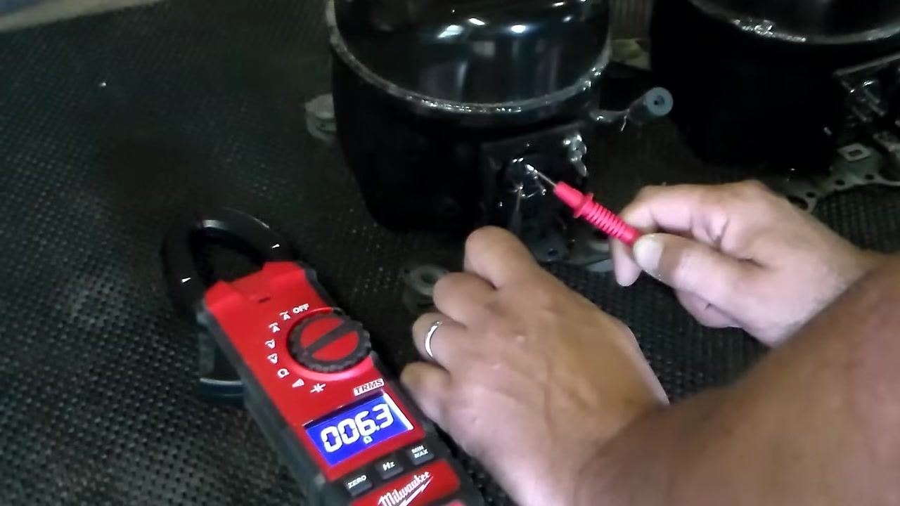
Step 12: Test resistance from the top terminal to the bottom left terminal. Move one probe to the top terminal and the other to the bottom left terminal. Expect a reading of about 6 ohms.
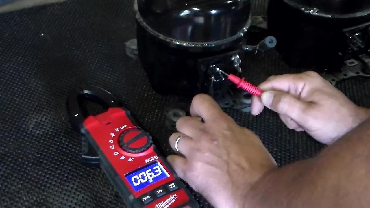
Step 13: Test resistance from the top terminal to the bottom right terminal. Move one probe to the top terminal and the other to the bottom right terminal. Expect a reading of about 4 ohms.
Interpreting the results: If the readings are approximately 10, 6, and 4 ohms, the used compressor windings are in good condition, just as with a new compressor.
Verifying compressor operation
Step 14: Attach the relay and power cord. Attach a relay and a power cord to the compressor terminals in preparation for a live power test.
Step 15: Plug in the compressor and listen for operation. Plug the compressor into a power receptacle and listen for it to start running. A noticeable operating sound confirms the compressor is functional.
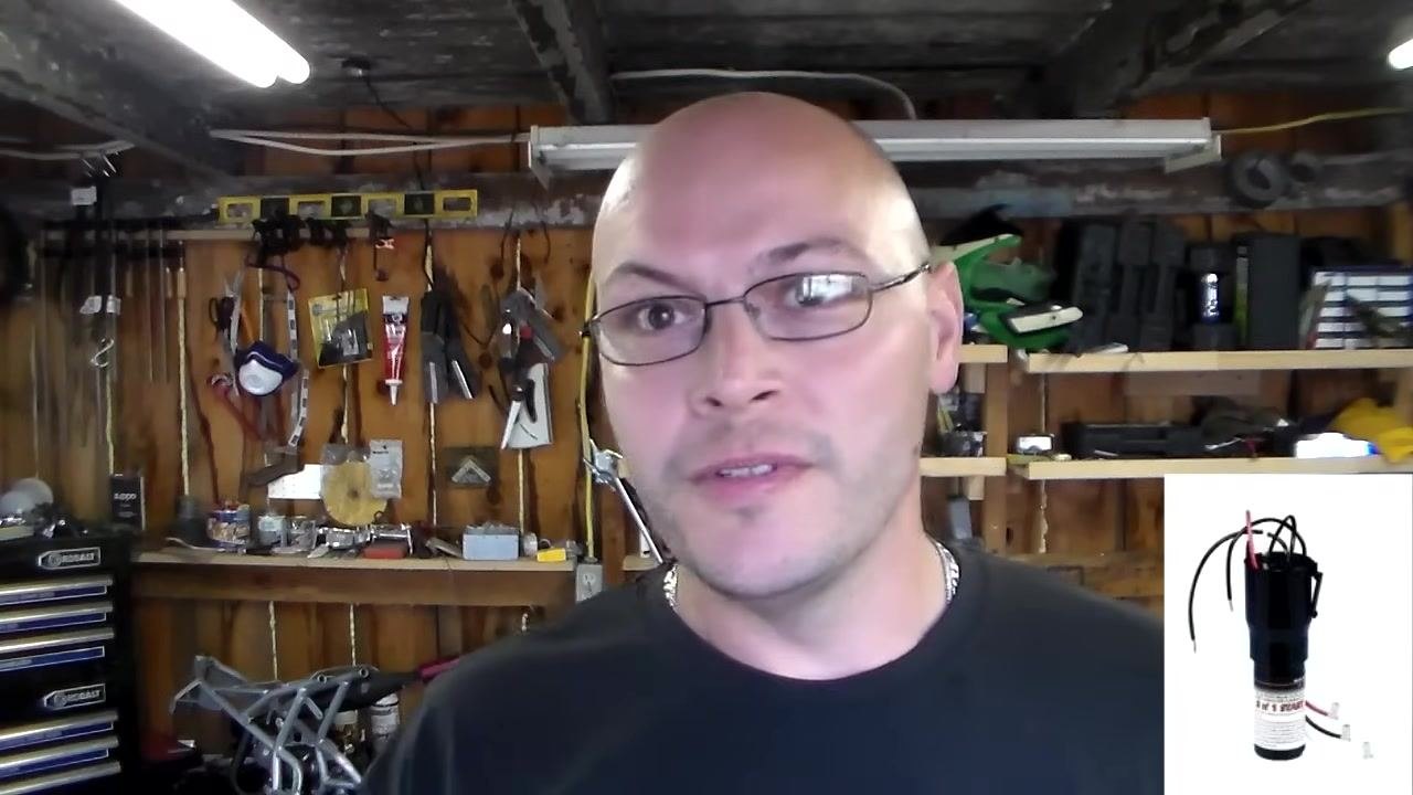
Troubleshooting a compressor that does not run
If you have tested the pins and received correct resistance readings, but the compressor still does not run, follow these checks:
- Ensure the refrigerator is unplugged before testing.
- Remove the relay from the compressor.
- Test the compressor pins for resistance as described above.
- If the compressor checks out but still does not run, proceed to test the relay.
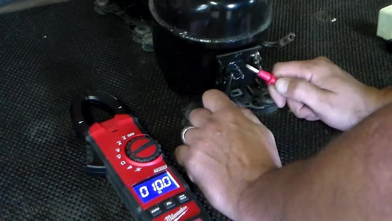
Step 16: Prepare for relay testing. Plug the refrigerator back in and set it so the freezer fan is running. Audible fan noise indicates the unit is powered and attempting to cool, which confirms you are ready to test the relay.
Testing the relay
Step 17: Set the multimeter to Volts AC. Set your multimeter to the Volts AC setting and prepare to test the voltage on the two wires connected to the compressor relay. Hold the relay and wires securely for testing.
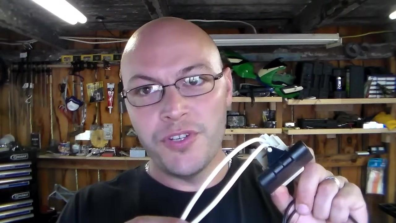
Step 18: Test for 120 volts AC. Place the multimeter probes on the two wires leading to the relay. If the reading shows 120 volts AC, the relay is receiving power.
Replacing the relay or start capacitor
Step 19: Replace the relay if it is faulty. If the relay itself is faulty, replace it with a new one. Note that relays can be relatively expensive for their size and function.
Step 20: Consider a three-in-one start capacitor as an alternative. If a replacement relay is too costly, a three-in-one start capacitor is a lower-cost option, typically priced around $10–$20. These are suitable for compressors rated at about 1/3 horsepower.

Step 21: Identify the three-in-one start capacitor. A three-in-one start capacitor typically has two wires coming off one end, which are used to connect the capacitor to the compressor.
Step 22: Wire the start capacitor. Connect the two wires from the start capacitor to the appropriate terminals on the compressor. Ensure all connections are secure and insulated.
Step 23: Verify compressor operation after wiring. Once wired, the three-in-one start capacitor should help the compressor start, allowing the refrigerator or freezer to begin cooling again.
Choosing replacement parts
When replacing a relay or start capacitor, you have two main options:
- Purchase factory replacement parts, designed specifically for your freezer model, from a reputable supplier.
- Use a universal replacement part, which may look different from the original but can function the same way despite the visual difference.
For field service work, carrying spare three-in-one start capacitors allows you to quickly power up a compressor and check amperage during service calls, supporting efficient troubleshooting and repair.
Verification checklist
Before concluding your test, confirm the following:
- Resistance readings across the three terminal pairs were consistent with expected values (approximately 10, 6, and 4 ohms).
- The multimeter returned to OL when the probes were not touching the terminals, confirming accurate readings.
- The compressor started and ran audibly when connected to a relay and power cord.
- If the compressor did not run despite passing the resistance test, the relay was tested for 120 volts AC and replaced or supplemented with a start capacitor as needed.
What's next
If the compressor fails the resistance test or produces a short-circuit-like reading, replace the compressor. If the compressor passes the resistance test but does not run, test and replace the relay, or install a three-in-one start capacitor as a lower-cost alternative. Once the compressor runs and the relay or capacitor tests correctly, reassemble the unit and confirm the refrigerator or freezer resumes normal cooling.

Generation details: cost, quality tiers
Docsie billed 4,000 credits ($2.80) to analyze this 8-minute video at standard quality. The rewrite, template fill and Word/PDF exports were included. The same video at each quality tier:
| Quality | Frames sampled | Credits | Approx. cost |
|---|---|---|---|
| Draft | every 16-30 s | 2,000 | $1.40 |
| Standard (this guide) | every 8-15 s | 4,000 | $2.80 |
| Detailed | every 4-7 s | 8,000 | $5.60 |
| Ultra | every 1-3 s | 16,000 | $11.20 |
Credits priced at $0.70 per 1,000; plans include a monthly allowance. Enterprise customers on on-premise or bring-your-own-model deployments run this on their own inference and pay no per-video credits.
Generated by Docsie Video-to-Docs on 2026-09-20 from a 7-minute video. Screenshots are frames from the source video and belong to their creator, Bill Newberry, whose original is embedded above. If you own this video and want the guide removed or credited differently, contact us and we will act within one business day.