
How to Test a Motor with a Multimeter
This procedure explains how to test a motor with a multimeter to verify that an induction motor is safe and ready for operation. It covers four essential checks — continuity, short circuit, ground leakage, and resistance — using a standard digital multimeter. Following these steps helps you confirm that motor windings are intact, properly insulated, and free of faults before connecting the motor to a power source.
Video: how to test 3 phase motor with multimeter by ELEKTRECA (2021). All credit for the demonstration goes to the creator; watch the original on YouTube. The written guide below was generated from this video by Docsie. Creator? Request a change or removal.
This procedure explains how to test a motor with a multimeter to verify that an induction motor is safe and ready for operation. It covers four essential checks — continuity, short circuit, ground leakage, and resistance — using a standard digital multimeter. Following these steps helps you confirm that motor windings are intact, properly insulated, and free of faults before connecting the motor to a power source.
Purpose
This SOP describes the process for testing an induction motor with a multimeter to detect open windings, shorted windings, and ground leakage faults. Completing these checks before energizing the motor reduces the risk of equipment damage and electrical hazards.
Scope
This procedure applies to induction motors with six labeled terminal leads (U1, U2, V1, V2, W1, W2) and is intended for use in a workshop or maintenance setting where a digital multimeter and basic hand tools are available.
Required equipment
- A digital multimeter with continuity and resistance modes (a UNI-T UT139E or equivalent model is suitable)
- Pliers and screwdrivers for accessing the terminal box
- A clamp meter (optional, for additional measurements)
- An induction motor with a clearly labeled terminal box
Safety note: Ensure the motor is fully disconnected from any power source before beginning any test.
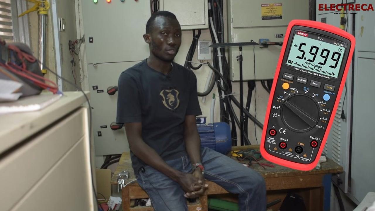
Identify your test equipment
Confirm that your digital multimeter is functioning correctly and set aside the tools you will need for the procedure. Along with the multimeter, keep pliers, screwdrivers, and a clamp meter within reach for accessing and testing the terminal box.
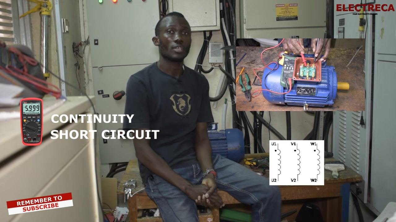
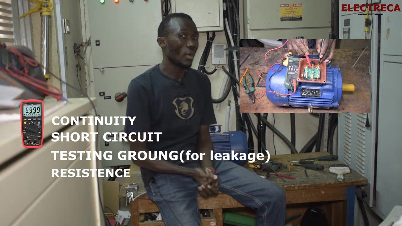
Review the tests you will perform
With a multimeter, you can perform four checks on an induction motor:
- Continuity test: Confirms that each winding's coil connections (U1-U2, V1-V2, W1-W2) are intact.
- Short circuit test: Confirms that the windings are not shorted to one another.
- Ground leakage test: Confirms that no winding is making contact with the motor body.
- Resistance test: Compares resistance values between windings to check for uniformity.
Locate and identify the motor terminals
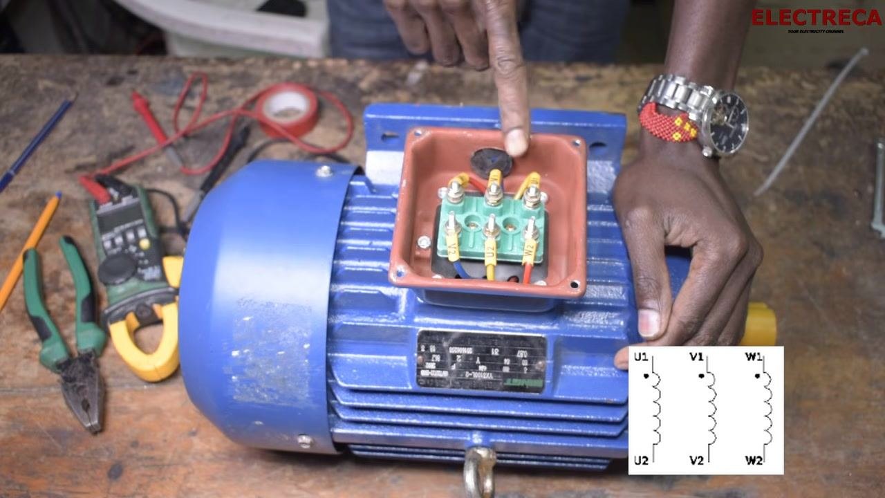
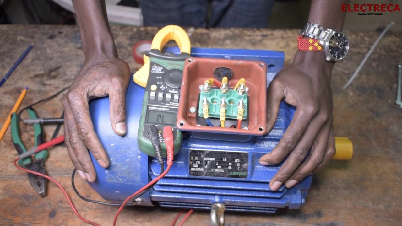
Open the terminal box and locate the six leads. These are typically labeled U1, U2, V1, V2, W1, and W2, and may also be color-coded. Correct identification of each terminal is essential before you begin testing.
Reference the winding diagram
Use the winding diagram to confirm which terminal pairs belong to the same winding: U1-U2, V1-V2, and W1-W2. This diagram guides both the continuity and resistance tests that follow.
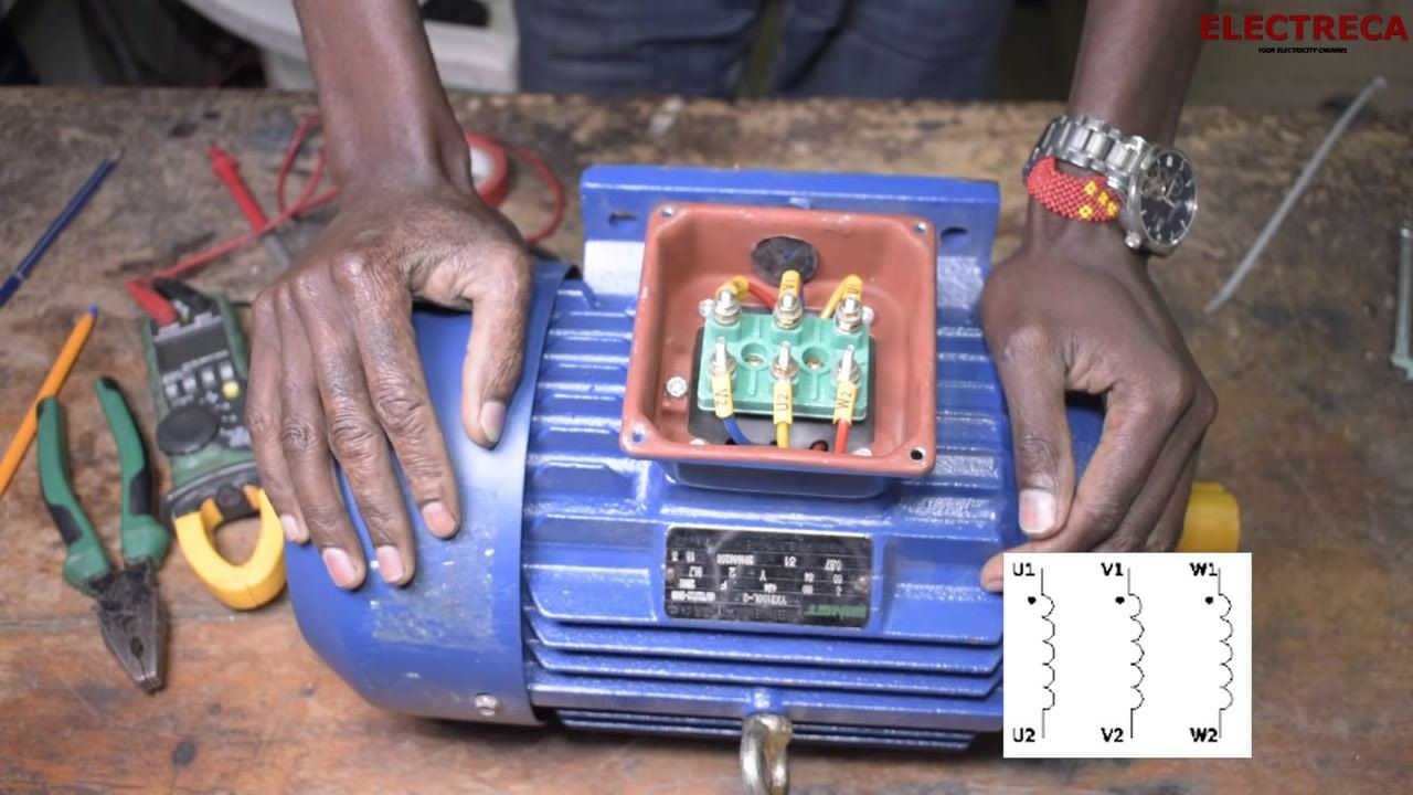
Match terminal pairs before testing
Note that matching terminal numbers (for example, U1 with U2) indicate the two ends of the same winding. Wire color can help confirm pairs, but be aware that all wires may sometimes appear the same color. If colors are not distinct, rely on the multimeter readings instead of color alone to identify winding pairs.
Prepare the multimeter for continuity testing
Safety note: Confirm the motor remains disconnected from any power source before proceeding. Set your digital multimeter to continuity mode, typically indicated by a sound wave or diode symbol, and keep the probes within easy reach of the terminal box.
Test continuity between each winding pair
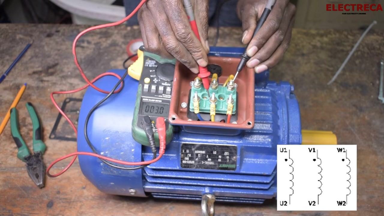
Place one probe on U1 and the other on U2, then listen for a beep or observe a low resistance reading to confirm continuity. Repeat this process for V1-V2 and then W1-W2. Each pair should register continuity, confirming the winding is intact.
Record the resistance value for each pair
As you test each pair, note the resistance value shown on the multimeter display. Healthy windings typically show low, similar resistance values across all three pairs. Example readings from this procedure were:
- U1-U2: 0.30 Ω
- V1-V2: 0.29 Ω
- W1-W2: 0.22 Ω
Consistent readings across all pairs indicate the windings are likely in good condition.
Verification: Confirm that all three winding pairs show continuity and similar resistance values. If any pair shows no continuity or a very high resistance reading, that winding may be open or damaged. If resistance values differ significantly between pairs, investigate further before proceeding.
Test for short circuits between windings
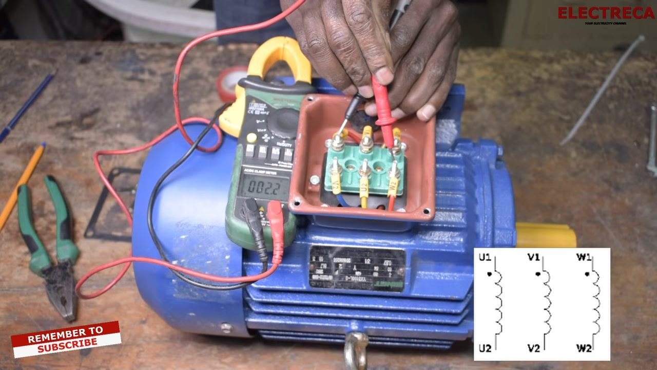
With the multimeter still in continuity mode, place one probe on U1 and the other on V1, then repeat for U1-W1 and V1-W1. These cross-winding tests should show no continuity — either no beep or an infinite resistance ("OL") reading. If you detect continuity between different windings (for example, U1 and V2), this indicates a short circuit, which must not be present. Only matching pairs (U1-U2, V1-V2, W1-W2) should ever show continuity.
Test for ground leakage
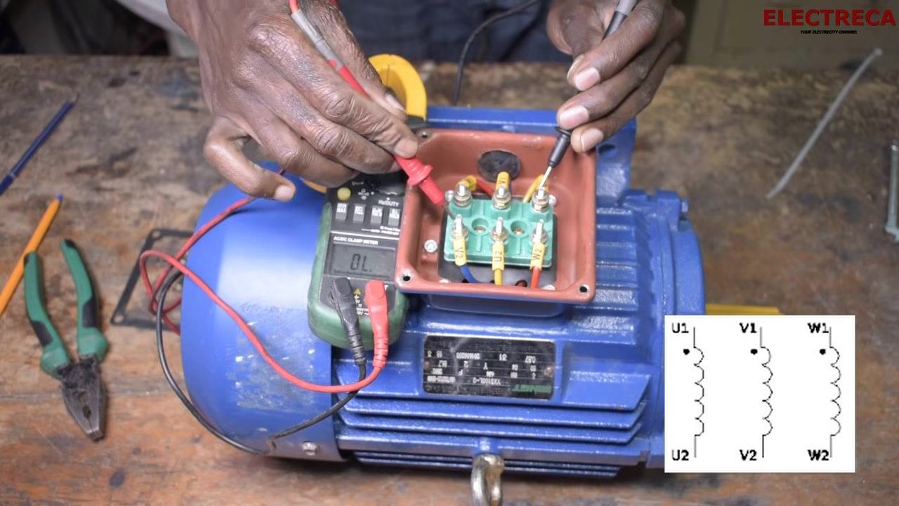
Place one multimeter probe on a winding terminal (for example, U1) and the other probe on a bare metal part of the motor body. Repeat this test for all six terminals. There should be no continuity — no beep and an infinite resistance ("OL") reading — between any terminal and the motor body. Any reading indicates ground leakage, which may result from damaged insulation or a cut wire touching the stator, and confirms the windings are not properly insulated from the motor frame.
Safety note: If you get a resistance reading or a beep during this test, there is a ground fault. Do not use the motor until the fault is repaired.
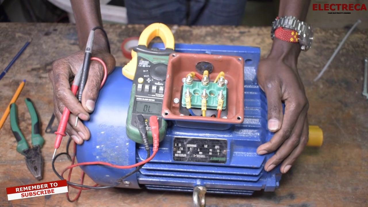
Confirm the motor body is conductive
Before finalizing your ground leakage results, verify that the multimeter correctly detects the motor body as conductive. Touch a probe to a bare metal part of the motor body while confirming the meter's response, ensuring your test setup is valid.
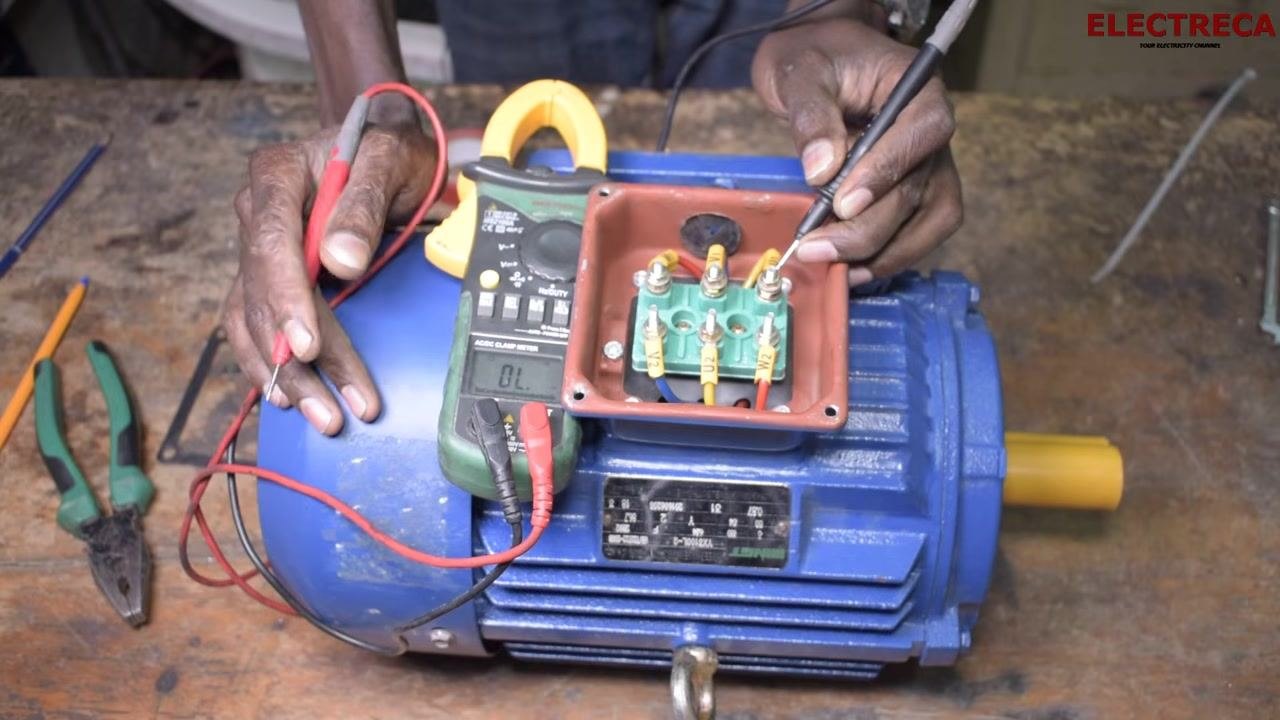
Test each remaining terminal against the motor body
Place one probe on the motor body and the other on each terminal in turn — U1, V1, W1, and any remaining leads. The display should show "OL" or infinite resistance for each terminal, confirming no ground leakage.
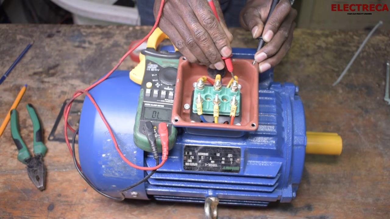
Confirm the motor is ready for use
Once continuity, short circuit, and ground leakage tests have all passed, the motor is confirmed healthy and ready for operation.
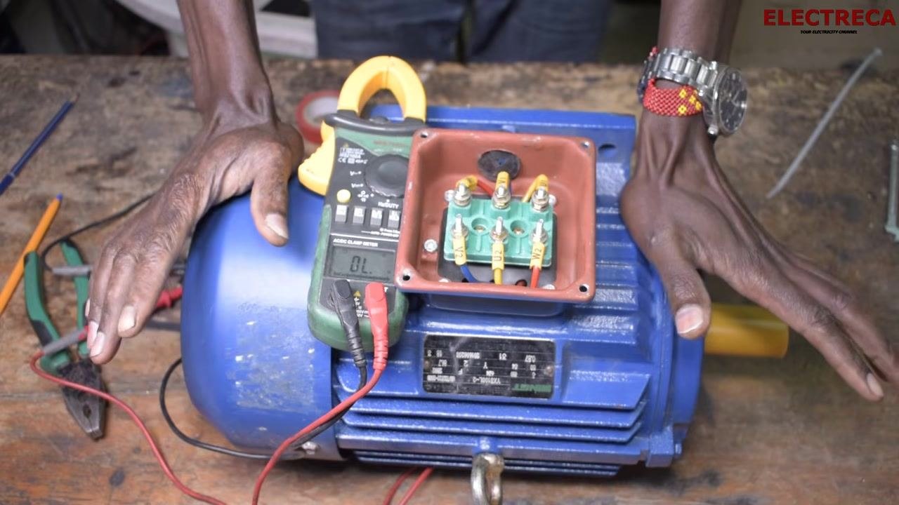
Complete all checks before powering the motor
Safety note: Double-check that continuity, short circuit, and ground leakage tests have all been performed and passed. Only connect the motor to a power source after confirming all results are satisfactory.
Verification and summary
Before returning the motor to service, confirm the following:
- All three winding pairs (U1-U2, V1-V2, W1-W2) show continuity with low, similar resistance values.
- No continuity exists between different windings, ruling out a short circuit.
- No continuity exists between any winding terminal and the motor body, ruling out ground leakage.
- The motor body was confirmed conductive before ground leakage testing began.
Any deviation from these results indicates a fault — an open winding, a short circuit, or ground leakage — that must be addressed before the motor is connected to power. Passing all four checks confirms the motor is safe and ready for operation.
Generation details: cost, quality tiers
Docsie billed 3,000 credits ($2.10) to analyze this 6-minute video at standard quality. The rewrite, template fill and Word/PDF exports were included. The same video at each quality tier:
| Quality | Frames sampled | Credits | Approx. cost |
|---|---|---|---|
| Draft | every 16-30 s | 1,500 | $1.05 |
| Standard (this guide) | every 8-15 s | 3,000 | $2.10 |
| Detailed | every 4-7 s | 6,000 | $4.20 |
| Ultra | every 1-3 s | 12,000 | $8.40 |
Credits priced at $0.70 per 1,000; plans include a monthly allowance. Enterprise customers on on-premise or bring-your-own-model deployments run this on their own inference and pay no per-video credits.
Generated by Docsie Video-to-Docs on 2026-09-20 from a 5-minute video. Screenshots are frames from the source video and belong to their creator, ELEKTRECA, whose original is embedded above. If you own this video and want the guide removed or credited differently, contact us and we will act within one business day.