
How to Test a Compressor Capacitor
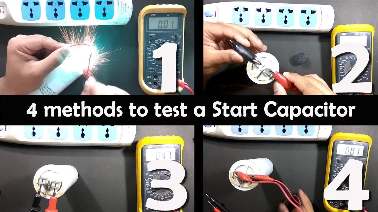
This procedure explains how to test a compressor capacitor — specifically the start capacitor used in single-phase induction motors — using four different testing methods. If your motor is not starting or is running at a very low speed, you should check the start capacitor to determine whether it is faulty. Some methods described below require a multimeter, while others do not.
Video: How to Test Motor Start and Motor Run AC Capacitor of ac fan and compressor by Tech StudyCell (2017). All credit for the demonstration goes to the creator; watch the original on YouTube. The written guide below was generated from this video by Docsie. Creator? Request a change or removal.
This procedure explains how to test a compressor capacitor — specifically the start capacitor used in single-phase induction motors — using four different testing methods. If your motor is not starting or is running at a very low speed, you should check the start capacitor to determine whether it is faulty. Some methods described below require a multimeter, while others do not.
Purpose
This SOP provides a standardized process for testing a start capacitor in a single-phase induction motor. It covers visual inspection, safety discharge procedures, and four distinct testing methods so you can confirm whether a capacitor is functioning correctly before replacing it or reinstalling it in a motor.

Scope
This procedure applies to anyone testing a start capacitor removed from a single-phase induction motor, including compressor motors. It covers testing with and without a multimeter, and includes both resistance-based and direct capacitance measurement approaches.
Required equipment and PPE
Depending on the method you choose, gather the following:
- Start capacitor to be tested
- Digital multimeter (required for Methods 3 and 4)
- Two connecting wires with alligator clips
- Power strip or AC supply (switched off until needed)
- Small DC source, such as a 12V battery (for Method 2)
- Small DC load, such as a buzzer (for Method 2)
- Insulated screwdriver for discharging terminals
- Non-conductive work surface
Safety precautions
- Always discharge the capacitor before handling or testing it by shorting its two terminals with an insulated screwdriver.
- Never touch the metallic parts of wires or capacitor terminals while the capacitor is charged.
- If you do not have a multimeter or a small DC source, you may use Method 1, but it is not recommended without proper safety precautions. Improper handling can result in severe electric shock.
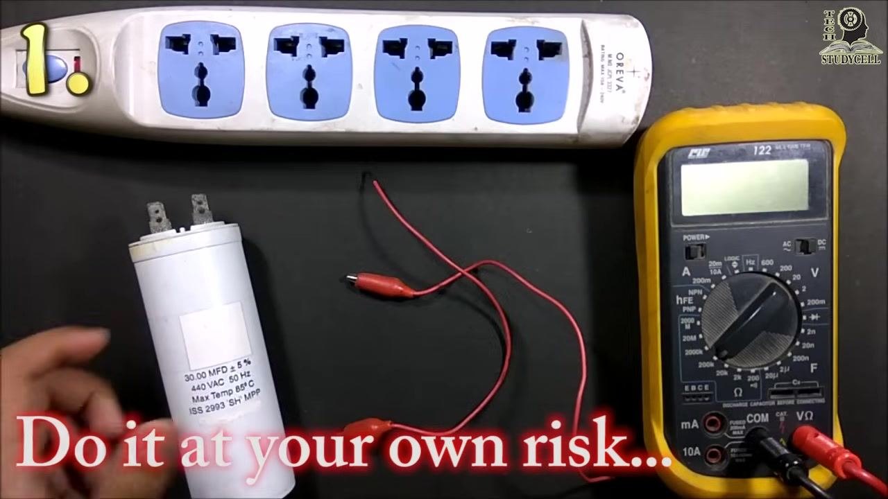
- Perform any live-wire test at your own risk and only if you are confident in handling electrical components safely.
Locate the start capacitor
Locate the start capacitor inside the single-phase induction motor. It is typically a cylindrical component connected to the motor wiring.
Discharge the capacitor before inspection
Before handling the capacitor, always short its two terminals using an insulated screwdriver to discharge any stored charge safely.
Inspect the capacitor for physical damage
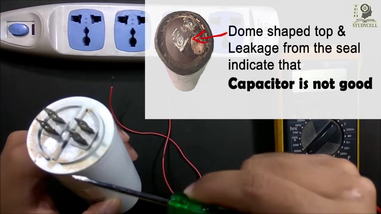
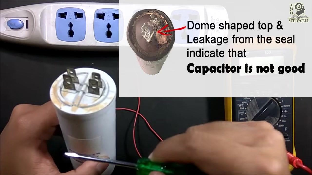
Examine the capacitor body for leakage or a dome-shaped top. A dome-shaped top or leakage from the seal indicates the capacitor is faulty and must not be reused.
If the capacitor shows no leakage or dome shape, it is physically intact and you can proceed to test it using one of the four methods below.
Verify the capacitor's rating label
Read the label on the capacitor to confirm its specifications before testing:
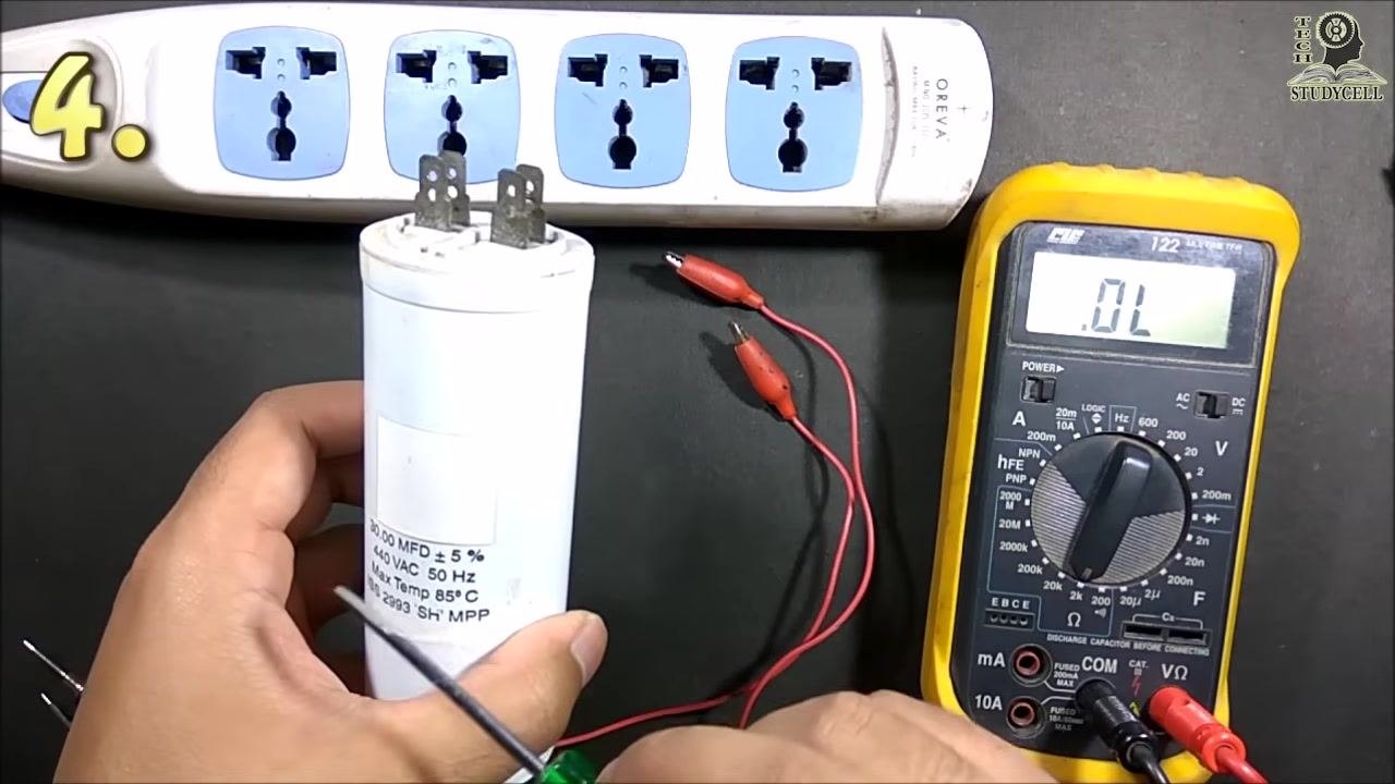
- Capacitance: 30.00 MFD (microfarads) ± 5%
- Voltage: 440 VAC
- Frequency: 50 Hz
- Maximum temperature: 85°C
- Standard: ISS 2993 SH MPP
You are now ready to test the capacitor using one of the four methods described below.
Method 1: Test by charging and discharging (without a multimeter)
Warning: This method involves briefly connecting the capacitor to a live AC supply. Improper handling can cause severe electric shock. Only proceed if you are confident and take all necessary safety measures.
Step 1: Set up the equipment
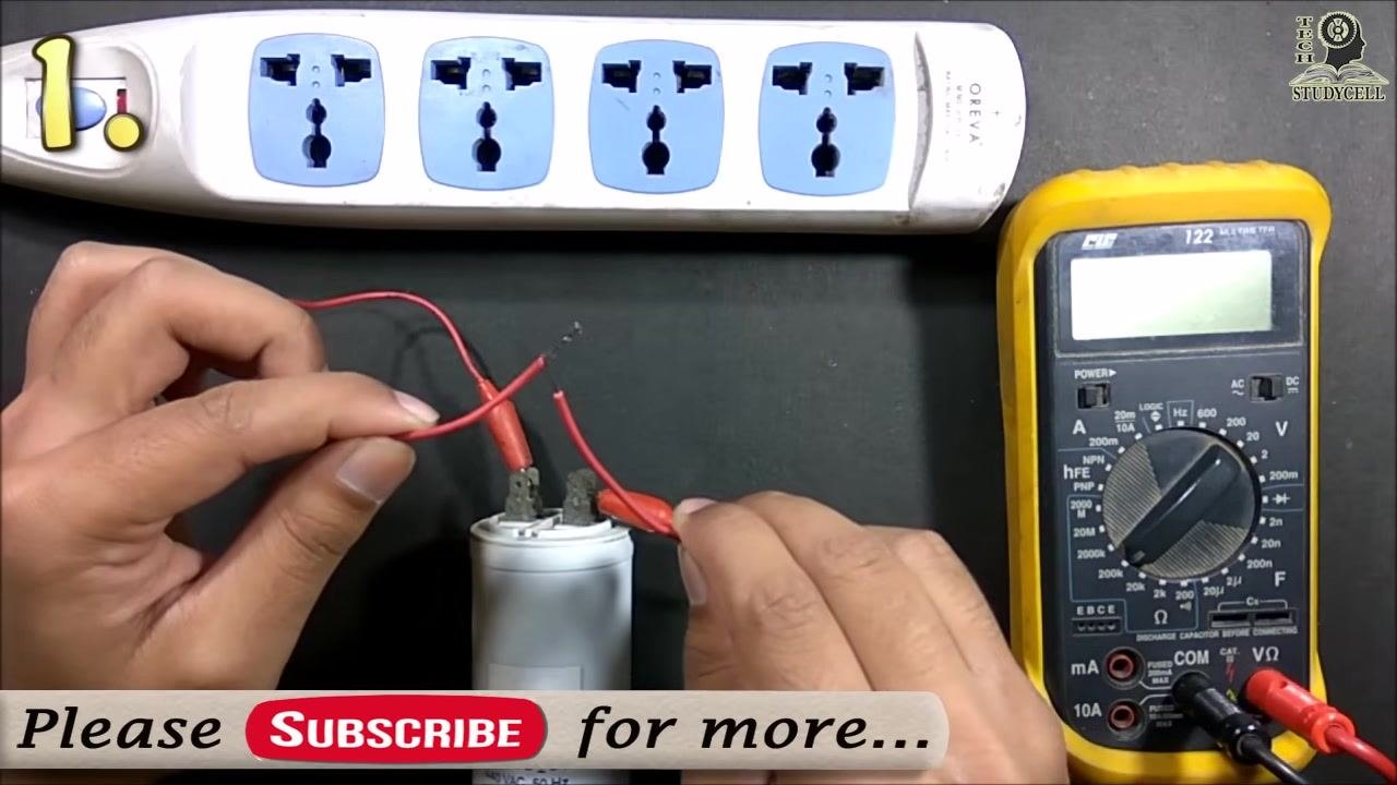
Place the start capacitor, connecting wires with alligator clips, and power strip on a non-conductive surface. Confirm the power supply is switched off before making any connections.
Step 2: Connect wires to the capacitor terminals
Attach one end of each connecting wire to the two terminals of the capacitor using alligator clips. Ensure the connections are secure and the wires are not touching each other. Confirm the power supply remains off.
Step 3: Position the wires for charging
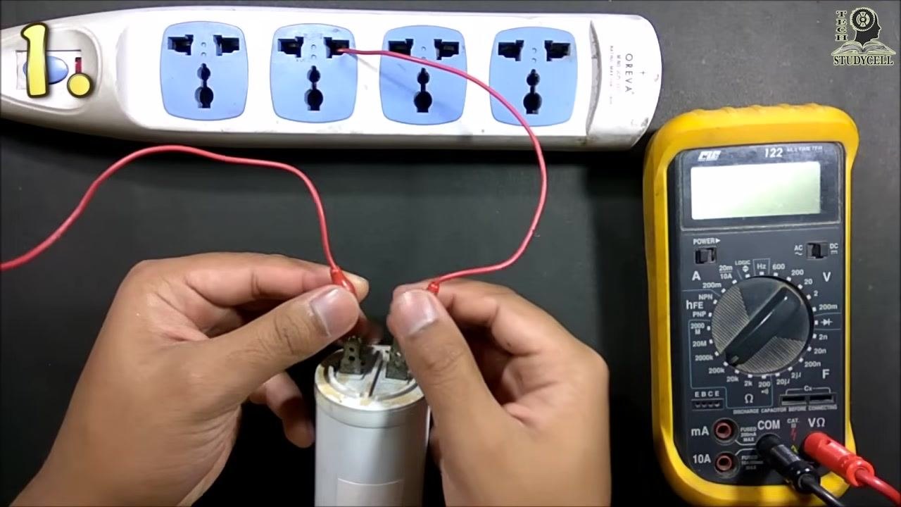
Hold the free ends of the two wires without touching any metallic part of the wires or the capacitor terminals directly.
Step 4: Charge the capacitor
Briefly connect the free ends of the wires to the live and neutral sockets of the power supply for less than one second, then disconnect immediately.
Warning: Do not keep the capacitor connected to the supply for more than a fraction of a second, and do not touch any metallic parts during this process.
Step 5: Prepare to discharge the capacitor
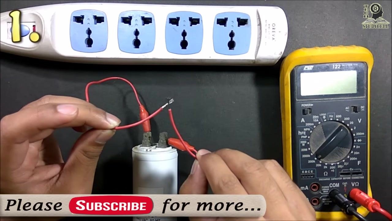
After charging, remove the wires from the power supply immediately. Hold the insulated part of the wires and bring the free ends together to short them.
Step 6: Discharge the capacitor and observe the result
Touch the free ends of the wires together to short them, discharging the capacitor. Listen for a spark sound or observe a visible spark at the point of contact.
Step 7: Interpret the results
If you hear a spark sound or see a spark when shorting the wires, the capacitor is charging and discharging correctly, indicating it is functional. If there is no spark or sound, the capacitor may be faulty and should be replaced.
Step 8: Complete the test safely
You may repeat the charging and discharging process once more for added confidence, always connecting the capacitor to the supply for only a fraction of a second each time. Never touch metallic parts during charging or discharging.
Note: This method confirms only that the capacitor charges and discharges; it does not measure the capacitance value.
Method 2: Test using a DC source and DC load
Step 1: Gather the equipment
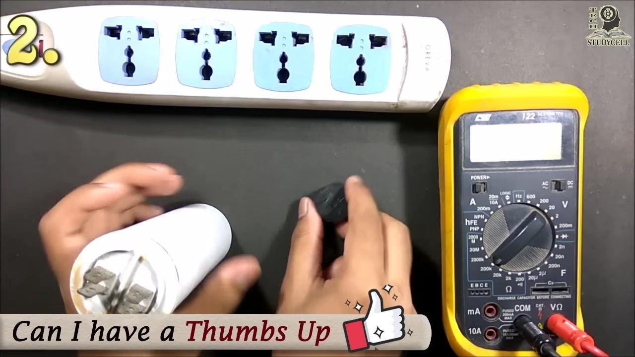
Prepare a start capacitor, a small DC source (such as a 12V battery), a small DC load (such as a buzzer), and connecting wires with alligator clips.
Step 2: Connect the capacitor to the DC source
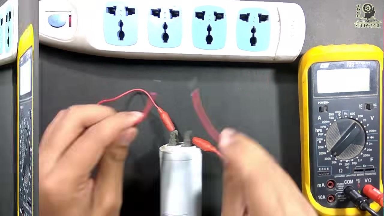
Attach the alligator clips to the capacitor terminals, ensuring the connections are secure and the wires are not touching each other.
Step 3: Charge the capacitor
Briefly connect the free ends of the wires to the positive and negative terminals of the DC source. Hold the wires by their insulated parts and avoid touching any metallic parts. Allow the capacitor to charge for a few seconds.
Step 4: Prepare the DC load
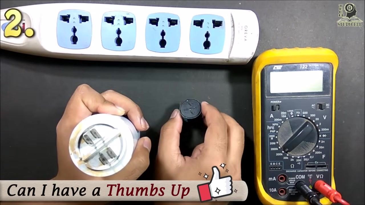
Hold the buzzer and get ready to connect it across the capacitor terminals.
Step 5: Connect the load and observe
After charging, disconnect the capacitor from the DC source. Immediately connect the buzzer across the capacitor terminals, ensuring correct polarity — the positive terminal of the buzzer to the positively charged terminal of the capacitor.
Step 6: Confirm discharge through the load
Listen for the sound from the buzzer, which indicates the capacitor is discharging through the load.
Step 7: Interpret the results
If the buzzer sounds for a short period, the capacitor is charging and discharging correctly, indicating it is functional. If there is no sound, the capacitor may be faulty and should be replaced.
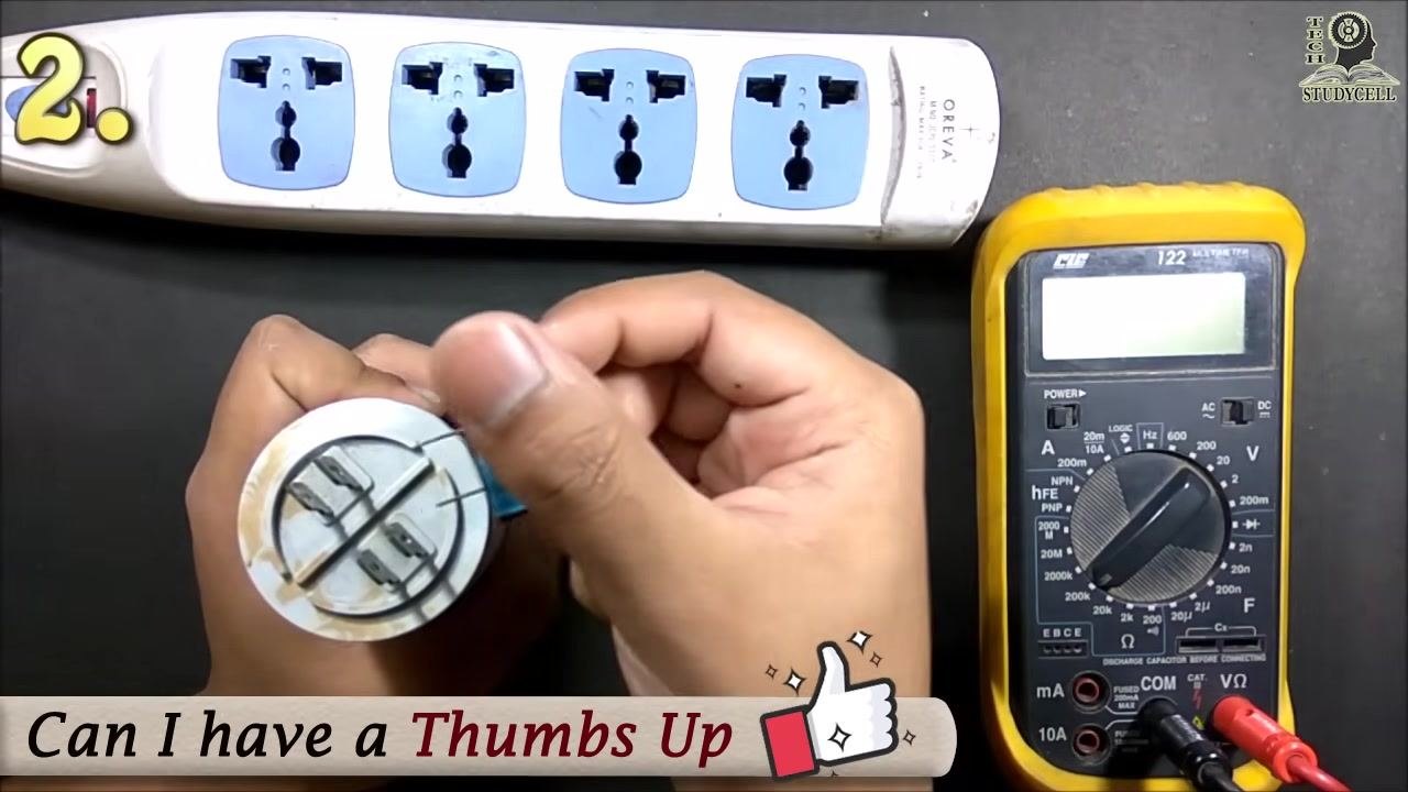
Limitation: This method only confirms whether the capacitor is charging and discharging. It does not provide an accurate measurement of the capacitance value.
Method 3: Test using a multimeter (resistance/ohmic scale)
Step 1: Discharge the capacitor
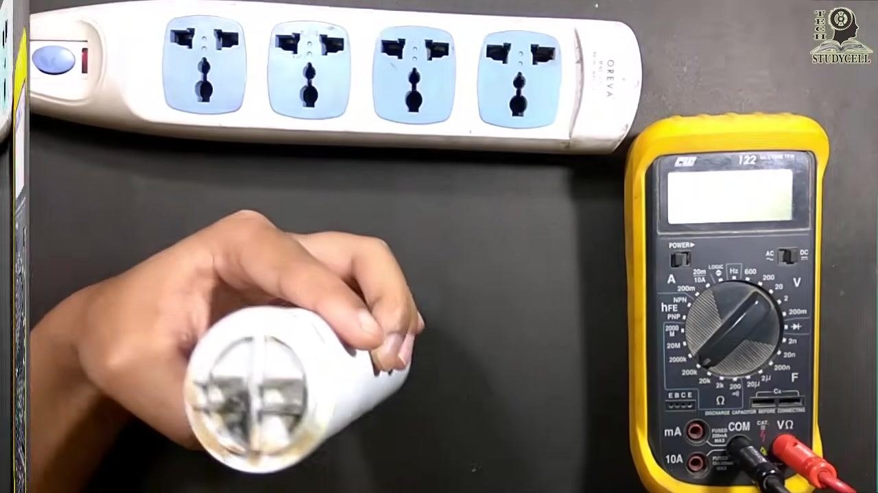
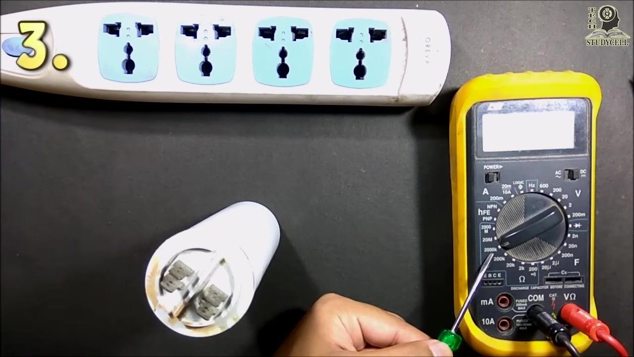
Before testing, fully discharge the capacitor by shorting its terminals with an insulated screwdriver. Hold the capacitor securely and touch the screwdriver blade across both terminals.
Step 2: Set up the multimeter
Insert the red lead into the VΩ port and the black lead into the COM port on the multimeter. Turn the dial to a high resistance range, such as 200kΩ.
Step 3: Connect the probes and observe the initial reading
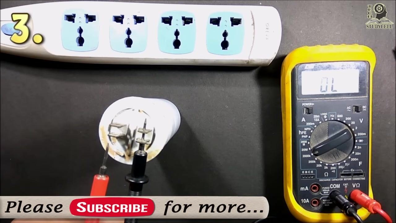
Touch one probe (black) to one terminal and the other probe (red) to the other terminal of the capacitor. The display initially shows "OL" (over limit), indicating no continuity at the start.
Step 4: Observe the reading as the capacitor charges
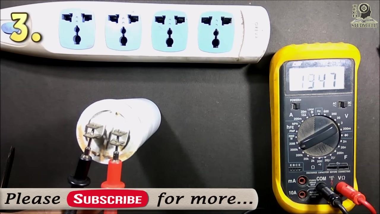
Keep the probes connected and watch the display as the value increases (for example, from "OL" to "225"), indicating the capacitor is charging.
Step 5: Wait for the reading to return to over limit
After a short time, the display returns to a high value or "OL," such as "1947," confirming the capacitor is holding a charge.
Step 6: Reverse the multimeter leads
Remove the probes from the capacitor and swap their positions — red to the terminal where black was, and vice versa. Touch the probes to the terminals again; the display should initially show "OL."
Step 7: Reconnect the reversed probes
With the leads reversed, touch the probes to the capacitor terminals again.
Step 8: Monitor the discharge process
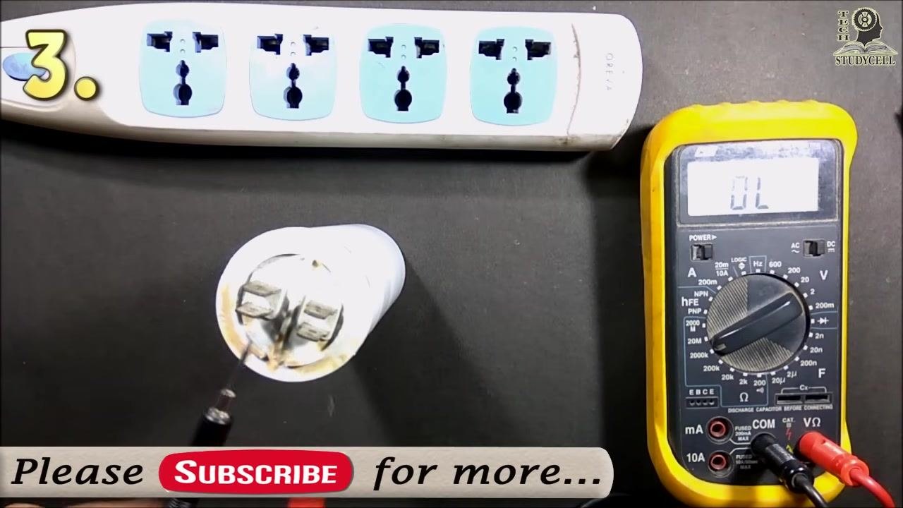
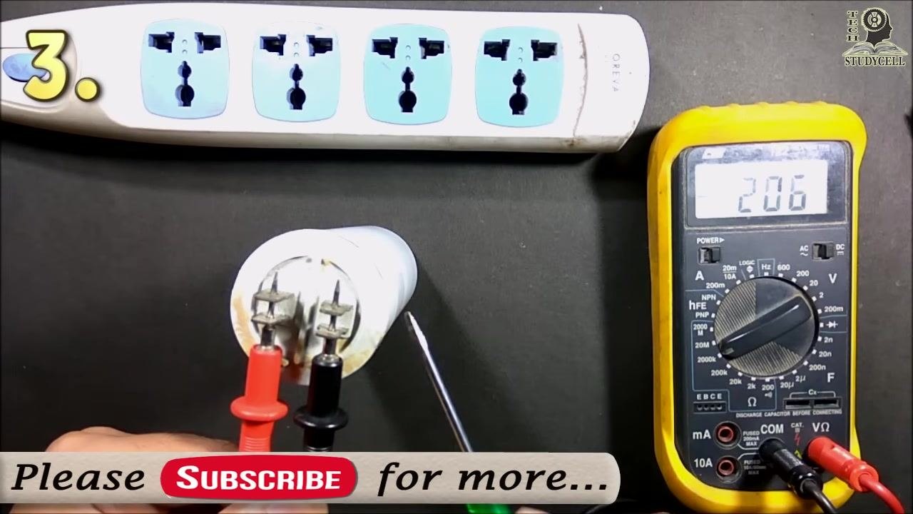
Continue observing the multimeter as the value decreases (for example, from "206" down to lower numbers), confirming the capacitor is discharging.
Step 9: Confirm full discharge
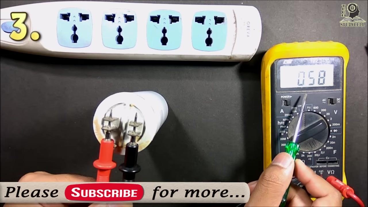
Wait until the reading drops to a low value, such as "058," indicating the capacitor is nearly fully discharged. Use an insulated screwdriver to short the terminals if necessary to ensure complete discharge.
Step 10: Repeat the test if needed
You may repeat the charging and discharging process to confirm the capacitor's behavior. The reading should increase while charging and decrease while discharging.
Method 4: Test using a multimeter (capacitance scale)
Measuring capacitance directly with a multimeter is the most accurate and recommended method for testing a compressor capacitor.
Step 1: Discharge the capacitor
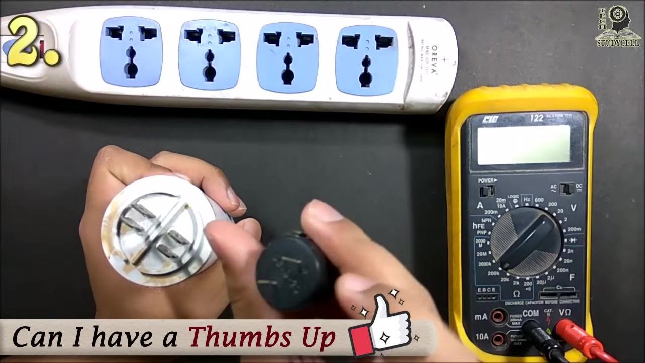
Before testing, use an insulated screwdriver to short the two terminals of the capacitor and fully discharge it.
Step 2: Set the multimeter to capacitance mode
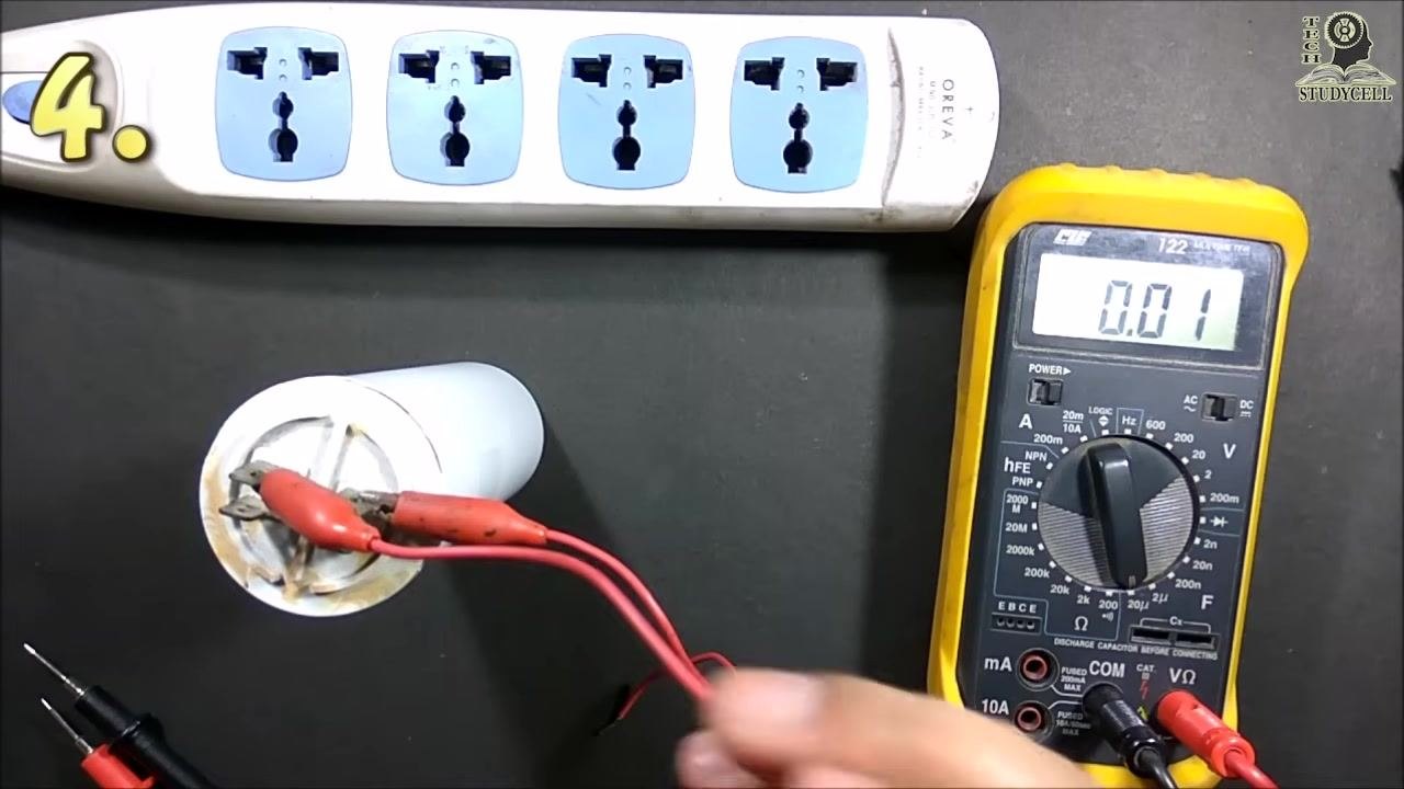
Turn the multimeter dial to the capacitance (F) setting. On this model, the range is marked "20μF" (microfarads). Confirm the display shows "OL," indicating it is ready for measurement.
Step 3: Connect the leads to the capacitor
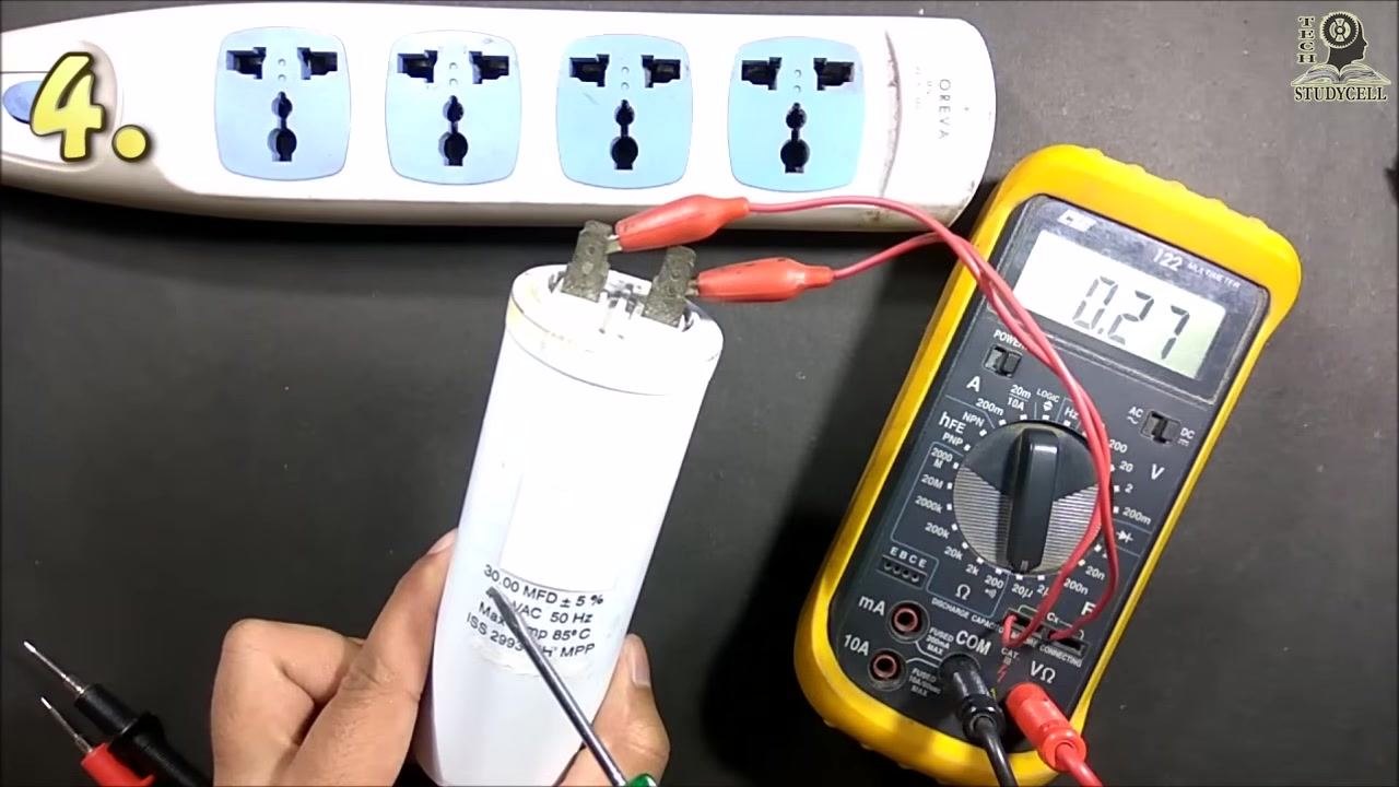
Attach the alligator clips from the multimeter leads to the two terminals of the capacitor, ensuring a secure connection. Observe the display as it begins to register a value.
Step 4: Check the multimeter's capacitance range
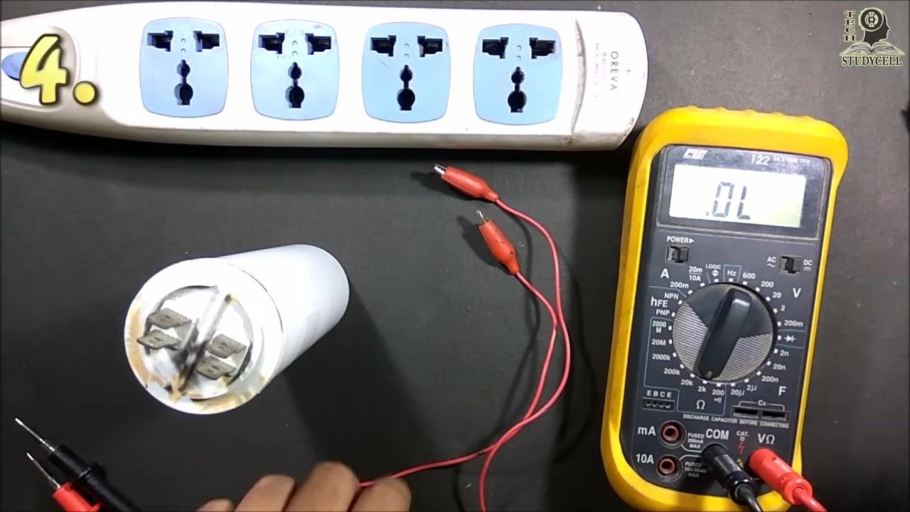
This multimeter can measure up to 20 microfarads (μF). The capacitor under test is labeled "30.00 MFD ± 5%," which exceeds the meter's maximum range. If the capacitance is above the meter's range, the display shows "OL." If the value remains "OL" after adjusting the leads or settings, the capacitor is too large for this meter.
Step 5: Read and interpret the measurement
If the capacitor value is within the meter's range, the display shows a numeric value, such as "9.30" for 9.3 μF. If the value is too high, the display shows "OL." Compare the measured value to the capacitor's rated value to determine if it is within specification.
Step 6: Verify against the rated specification
Use a screwdriver or pointer to indicate the capacitor's label and confirm its rated capacitance, such as "30.00 MFD ± 5%." If the measured value is significantly lower than the rated value, the capacitor may be faulty.
Step 7: Confirm your findings
If your multimeter cannot measure the full value of the capacitor, use a meter with a higher capacitance range or verify the result with another testing method.
Verification and summary
You can confirm a start capacitor's condition using any of the four methods below:
- Charging and discharging without a multimeter (visual/audible spark check)
- Charging and discharging using a DC source and DC load (buzzer sound check)
- Charging/discharging behavior observed on a multimeter's resistance scale
- Direct capacitance measurement compared against the rated specification
Measuring capacitance directly with a multimeter is the most accurate and recommended method for testing a compressor capacitor. Always ensure the capacitor is fully discharged before handling or testing it, to avoid electric shock or damage to your multimeter.
What's next
If your multimeter cannot measure the full rated value of your capacitor, use a meter with a higher capacitance range or cross-check the result using one of the other three methods described above. If a capacitor fails any of these tests — through lack of spark, lack of buzzer sound, or a significantly lower capacitance reading than its rated value — replace it before reinstalling it in the motor.
Generation details: cost, quality tiers
Docsie billed 4,500 credits ($3.15) to analyze this 9-minute video at standard quality. The rewrite, template fill and Word/PDF exports were included. The same video at each quality tier:
| Quality | Frames sampled | Credits | Approx. cost |
|---|---|---|---|
| Draft | every 16-30 s | 2,250 | $1.57 |
| Standard (this guide) | every 8-15 s | 4,500 | $3.15 |
| Detailed | every 4-7 s | 9,000 | $6.30 |
| Ultra | every 1-3 s | 18,000 | $12.60 |
Credits priced at $0.70 per 1,000; plans include a monthly allowance. Enterprise customers on on-premise or bring-your-own-model deployments run this on their own inference and pay no per-video credits.
Generated by Docsie Video-to-Docs on 2026-09-20 from a 8-minute video. Screenshots are frames from the source video and belong to their creator, Tech StudyCell, whose original is embedded above. If you own this video and want the guide removed or credited differently, contact us and we will act within one business day.