
How to Test a Circuit Breaker with a Multimeter
This procedure describes how to test a circuit breaker with a multimeter to confirm whether it is functioning correctly. It covers both a continuity test and an AC voltage test, allowing you to determine if a breaker is good or if it needs to be replaced.
Video: How To Test A Circuit Breaker With A Multimeter by Electro University (2022). All credit for the demonstration goes to the creator; watch the original on YouTube. The written guide below was generated from this video by Docsie. Creator? Request a change or removal.
Purpose
This procedure describes how to test a circuit breaker with a multimeter to confirm whether it is functioning correctly. It covers both a continuity test and an AC voltage test, allowing you to determine if a breaker is good or if it needs to be replaced.

Scope
This SOP applies to anyone who needs to check the condition of a circuit breaker inside a residential or general electrical panel box using a multimeter. It includes the steps for opening the panel, isolating power, and performing continuity and voltage checks.
Required equipment and PPE
Before you begin, gather the following insulated tools:
- Multimeter (with ohm and AC voltage measurement capability)
- Set of insulated screwdrivers (various sizes)
- Insulated gloves

Using insulated tools and gloves is essential to prevent electrical shock and injuries. Always wear this protective equipment before working inside the circuit breaker box.
Procedure
Step 1: Open the circuit breaker box
Put on your insulated gloves before touching the panel. Use an insulated screwdriver to remove the screws at the corners of the circuit breaker box, then carefully open the box to access the internal wiring and components.
Step 2: Locate the power source and switch it off
Identify the main or general switch inside your electrical panel box. Flip the main switch to the OFF position to ensure there is no live current while you work.
Step 3: Identify the circuit breaker to test
Examine the inside of the opened panel to locate the circuit breakers and associated wiring. Confirm that the box is still connected to the power cable, but make sure the main switch remains OFF while you identify the breaker.
Step 4: Set up the multimeter for a continuity test
Take your multimeter and turn the dial to the ohms (Ω) setting, usually represented by the omega symbol. Ensure the multimeter probes are connected to the correct ports (COM and Ω) before testing.
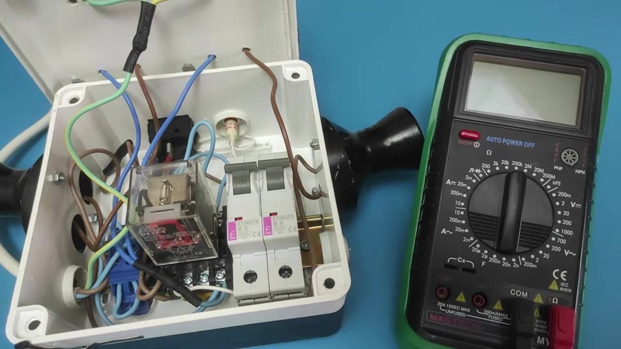
Step 5: Test the circuit breaker for continuity
Place one probe on each end of the circuit breaker you wish to test and observe the reading on the multimeter display.
- Desired result: The multimeter reads 0 ohms, indicating continuity and that the breaker is good.
- If you see resistance (any value other than 0 ohms): The circuit breaker is faulty and should be replaced.
Step 6: Interpret readings in the ON and OFF positions
With the circuit breaker in the ON position, place the multimeter probes on both terminals of the breaker and confirm the display reads 0.00 ohms, which indicates proper continuity and a functioning breaker.
Switch the circuit breaker to the OFF position, then place the probes on the same terminals again. Confirm the display now reads 1 ohm (or infinite resistance), which means the circuit is open and the breaker is functioning correctly.
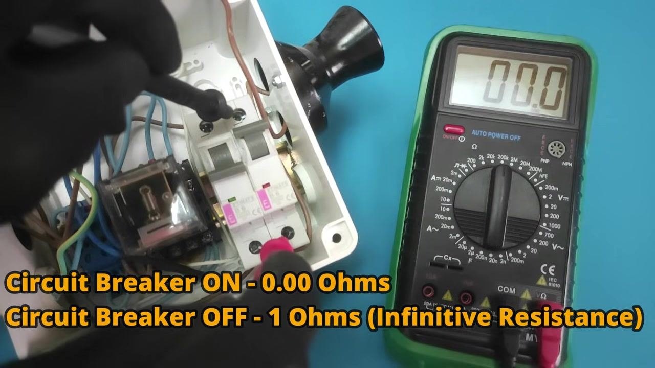
Expected results:
- Circuit breaker ON: 0.00 ohms
- Circuit breaker OFF: 1 ohm (infinite resistance)
Step 7: Perform an alternative test by measuring AC voltage
Turn the multimeter dial to the AC voltage (V~) setting. Connect one probe to the voltage output terminal of the circuit breaker and the other probe to a ground terminal, then observe the display for the AC voltage reading.
- The expected voltage should be between 120 and 240 volts, depending on your local supply.
- If the voltage is significantly lower or unstable (for example, 180 volts), this may indicate the circuit breaker is starting to fail.
Step 8: Complete the test and restore the panel
Once testing is complete, turn the main switch back ON if it was turned off. Carefully reattach the cover of the circuit breaker box using the insulated screwdriver, then remove your insulated gloves and store all tools safely.
Verification and summary
By following these steps, you can confidently test a circuit breaker for both continuity and operational voltage using a multimeter. A breaker reading 0.00 ohms when ON and 1 ohm (infinite resistance) when OFF is functioning correctly, while an AC voltage reading well below the expected 120–240 volt range signals a breaker that may be failing.
Always prioritize safety by using insulated tools and personal protective equipment, and ensure the power is off before beginning any electrical work.
Generation details: cost, quality tiers
Docsie billed 1,500 credits ($1.05) to analyze this 3-minute video at standard quality. The rewrite, template fill and Word/PDF exports were included. The same video at each quality tier:
| Quality | Frames sampled | Credits | Approx. cost |
|---|---|---|---|
| Draft | every 16-30 s | 750 | $0.52 |
| Standard (this guide) | every 8-15 s | 1,500 | $1.05 |
| Detailed | every 4-7 s | 3,000 | $2.10 |
| Ultra | every 1-3 s | 6,000 | $4.20 |
Credits priced at $0.70 per 1,000; plans include a monthly allowance. Enterprise customers on on-premise or bring-your-own-model deployments run this on their own inference and pay no per-video credits.
Generated by Docsie Video-to-Docs on 2026-09-20 from a 2-minute video. Screenshots are frames from the source video and belong to their creator, Electro University, whose original is embedded above. If you own this video and want the guide removed or credited differently, contact us and we will act within one business day.