
How to Tell If an Ac Compressor Is Bad
Before you condemn a compressor and order a replacement, you need to confirm it is actually faulty. This SOP walks you through how to tell if an AC compressor is bad by measuring winding resistance, checking the internal thermal overload, testing for shorts to ground, inspecting the plug and terminals, and verifying three-phase motor windings. Only replace a compressor once you have thoroughly tested and verified that it is burned out.
Video: Testing if an HVACR Compressor is Shorted to Ground, Open, or Overload Tripped! by AC Service Tech LLC (2020). All credit for the demonstration goes to the creator; watch the original on YouTube. The written guide below was generated from this video by Docsie. Creator? Request a change or removal.
Before you condemn a compressor and order a replacement, you need to confirm it is actually faulty. This SOP walks you through how to tell if an AC compressor is bad by measuring winding resistance, checking the internal thermal overload, testing for shorts to ground, inspecting the plug and terminals, and verifying three-phase motor windings. Only replace a compressor once you have thoroughly tested and verified that it is burned out.
Purpose
This procedure gives you a repeatable method for diagnosing compressor electrical faults, including:
- Windings shorted to ground
- Open windings
- An open internal thermal limit (overload protector)
- Damaged plug terminals or lugs
Scope
This SOP applies to the compressor types you are most likely to encounter in the field:
- Scroll compressors
- Rotary compressors (including three-phase units found in mini-split systems)
- Reciprocating compressors (commonly found in outdoor units, single-phase)
Required equipment and PPE
- Multimeter capable of measuring resistance in ohms (a DL489 True RMS meter or similar)
- Safety glasses
- Nitrile gloves
- Compressor lug repair kit (for use only when a terminal lug is damaged)
- Clear access to the compressor compartment and terminals
Safety note: Before performing any electrical test on a compressor, turn off the power supply to the contactor and verify with your multimeter that no voltage is present. Always follow proper lockout/tagout procedures before touching electrical components.
Preparing to test the compressor
Step 1: Confirm the unit is de-energized and access the compressor. Open the access panel to the compressor compartment and confirm you have a clear view of the terminals and wiring. Verify with your multimeter that there is no voltage present before you touch any wires.

Step 2: Disconnect the compressor wires. Terminal access is often difficult because of its location, so start your diagnosis at the wiring connections near the top of the unit. Identify the wire connected to the HERM (hermetic) terminal on the capacitor, then disconnect the wires leading to the compressor to isolate it for testing.
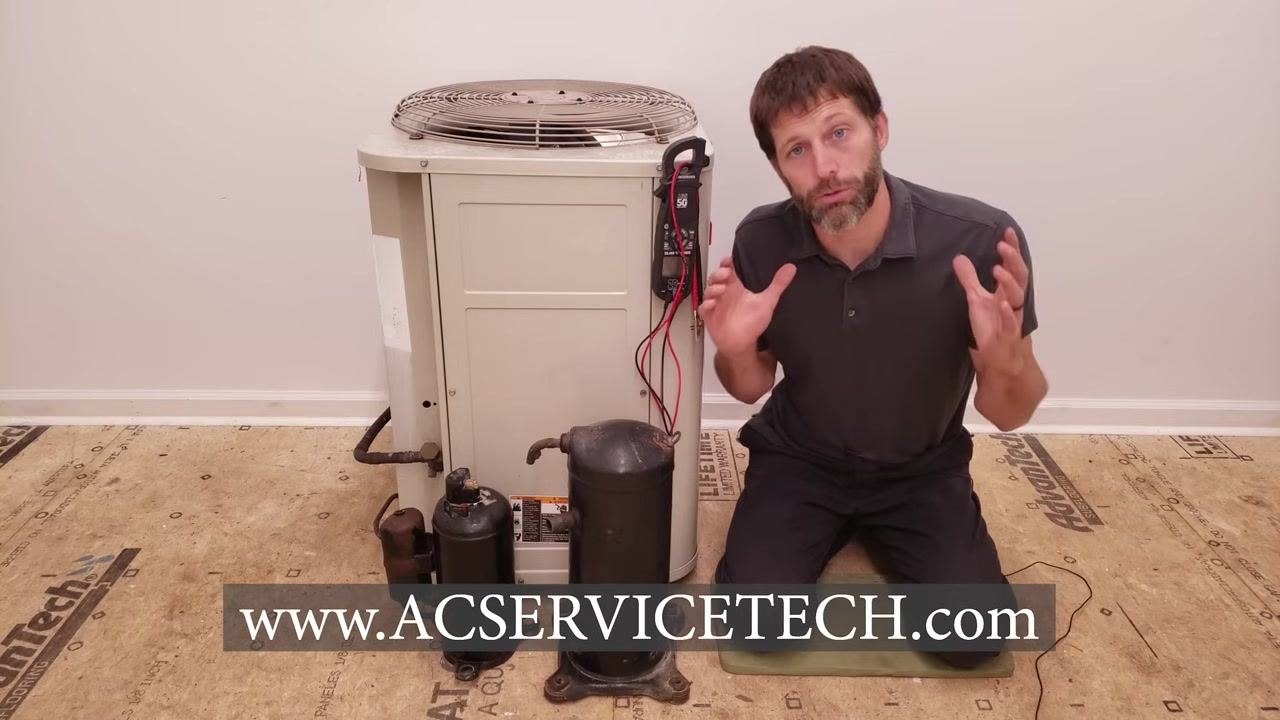
Step 3: Fully isolate the compressor terminals. Carefully disconnect each wire (in this case, yellow, black, and blue) from its terminal. Make sure all wires to the compressor are disconnected before you take any resistance readings.
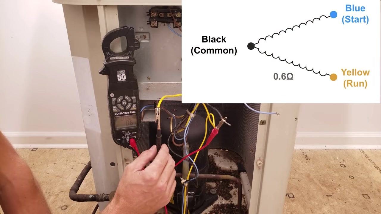
Measuring compressor winding resistance
Step 4: Measure resistance across the winding pairs. Set your multimeter to the resistance (ohms, Ω) setting. Inspect the terminals for corrosion and clean them if needed so your probes or alligator clips make good contact. Then measure and record:
- Black (Common) to Yellow (Run)
- Black (Common) to Blue (Start)
- Blue (Start) to Yellow (Run)
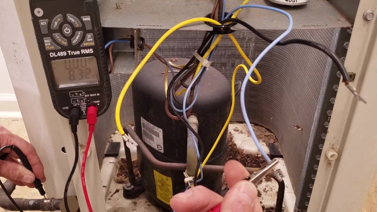
In this example, the readings were 0.6 Ω, 1.7 Ω, and 2.3 Ω respectively. The lowest reading identifies Common-to-Run, the middle reading identifies Common-to-Start, and the highest reading identifies Start-to-Run.
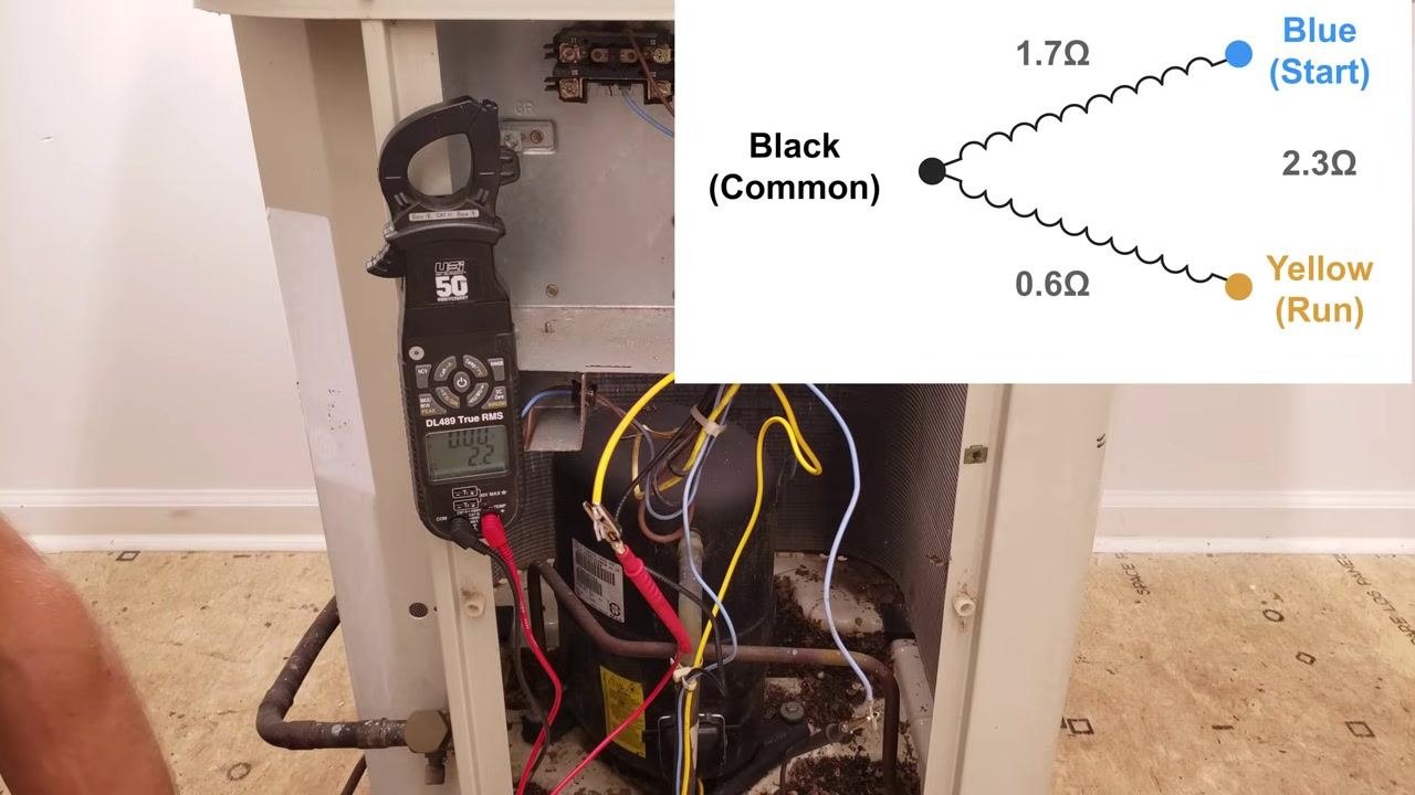
Step 5: Verify your readings by checking that they add up correctly. Measure between Start and Run again and compare it to the sum of Common-to-Run plus Common-to-Start. In this example, the meter read 2.2 Ω between Blue and Yellow, which is very close to the calculated 2.3 Ω (0.6 Ω + 1.7 Ω). A close match like this confirms your readings are accurate and that the windings between those terminals are intact.
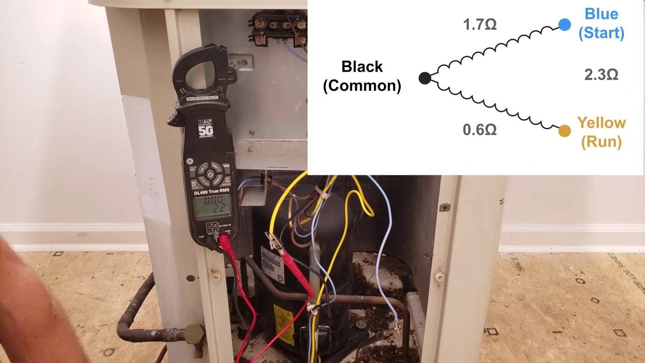
Understanding thermal overload protection
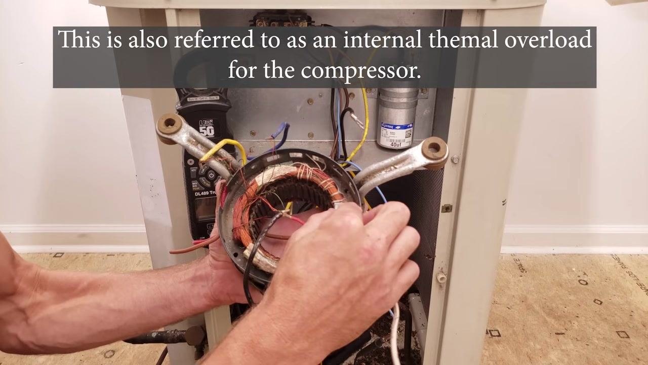
Step 6: Understand what the thermal limit protects. The black wire is the Common terminal. If you can measure resistance from Common to the other terminals, the internal thermal limit (overload protector) is intact. This device is a safety component inside the compressor that opens the circuit to prevent overheating; on small fractional-horsepower compressors it may be accessible externally, but on larger compressors it is internal and cannot be reached.
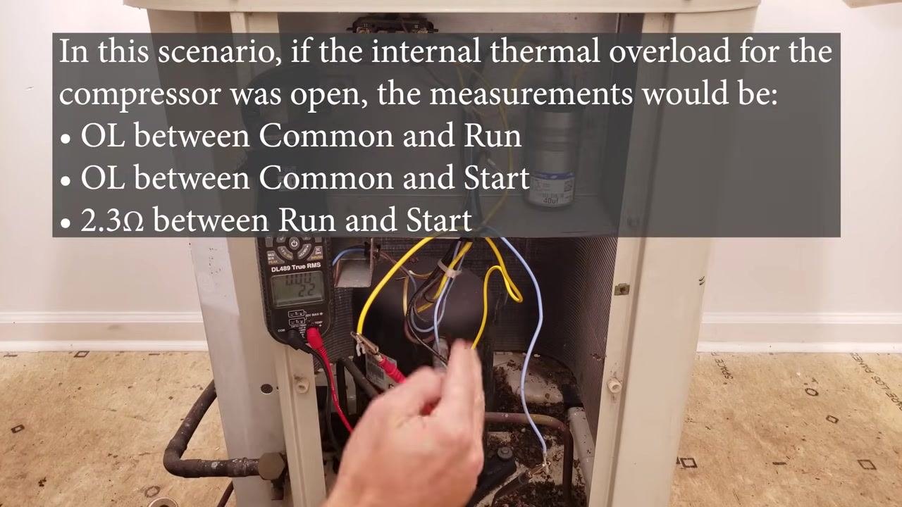
Step 7: Recognize the readings of an open thermal overload. If the overload has opened, typically due to overheating, your readings will change. Expect:
- OL (Open Line) between Common and Run
- OL between Common and Start
- 2.3 Ω between Run and Start
"OL" on your meter means no continuity. If you see this pattern and the compressor is hot, let it cool down and retest, since the overload may reset once the temperature drops. If it remains open after cooling, further investigation or replacement may be needed.
Checking for shorts to ground
Step 8: Confirm the unit is still de-energized before continuing. Make sure the power to the unit remains completely off and allow the compressor to cool if it has been running. Confirm your multimeter is ready to measure resistance before you proceed to the ground check.
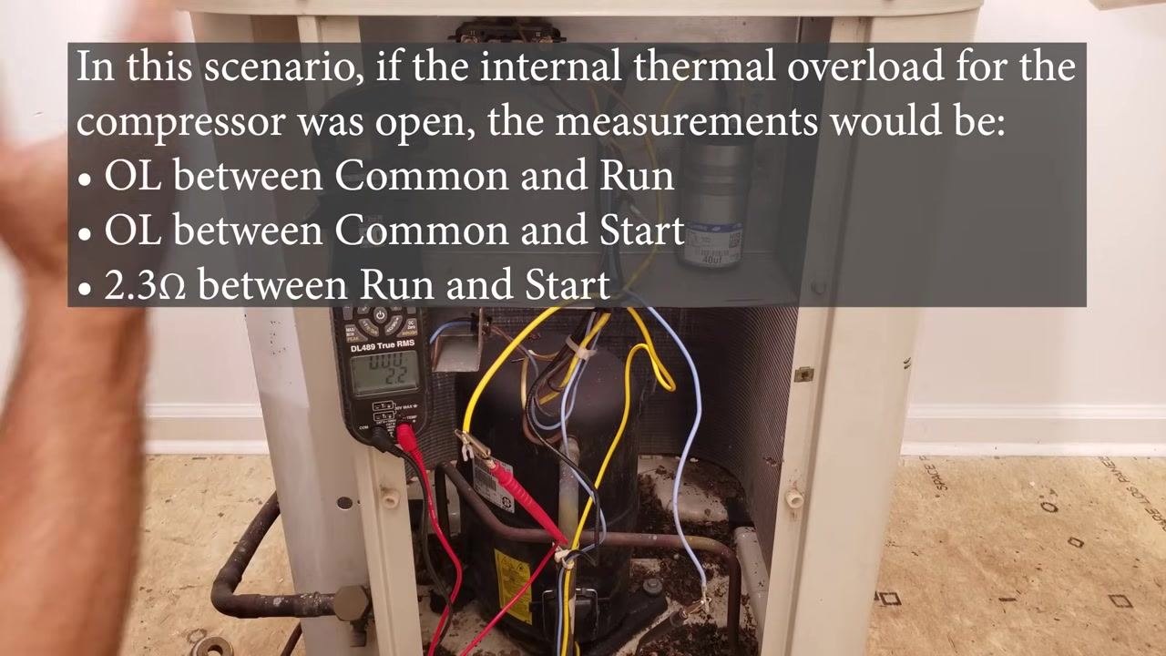
Step 9: Prepare a clean ground reference point. Clean a small section of the copper tube on the compressor so your meter probe makes good contact. This cleaned section becomes your ground reference for the short-to-ground test.
Step 10: Check each terminal wire for a short to ground. Touch one probe to a compressor terminal wire and the other to the cleaned copper tube. If there is no short to ground, the meter reads "OL." If you have already verified good resistance values between all terminal pairs, you only need to check one wire for a short to ground.
Step 11: Investigate any unusual resistance readings. If you measure a value in the kilo-ohm or mega-ohm range, or the meter reads "OL" unexpectedly, further investigation is needed before you draw a conclusion.
Checking the plug terminal
Step 12: Move to the plug terminal if readings are inconclusive. If you measure "OL" or a high resistance value between any pair of terminals (Common-Run, Common-Start, or Start-Run) and you believe the thermal overload is actually closed, the next place to check is the plug terminal.
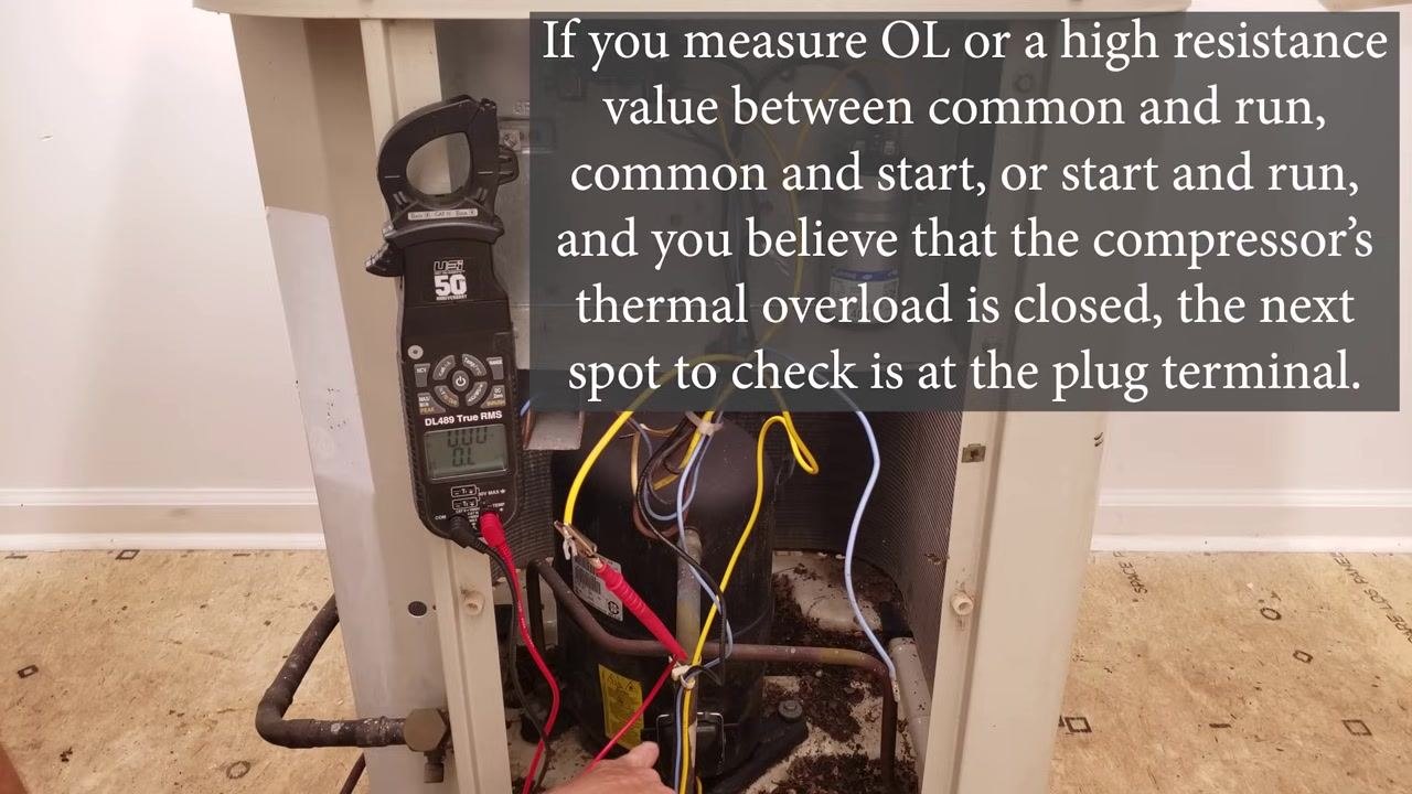
Step 13: Put on safety glasses before removing the plug. Some compressor plugs can leak refrigerant or oil when removed, so wear safety glasses and proceed carefully.
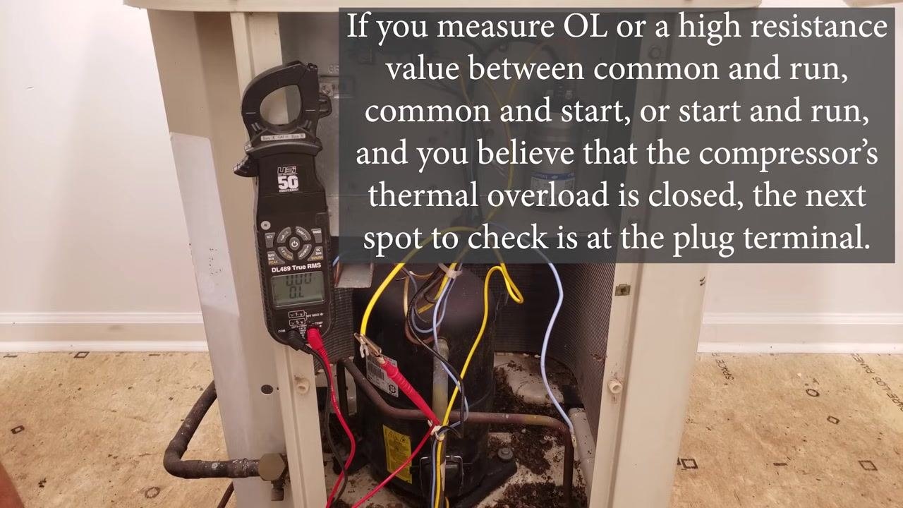
Step 14: Locate the plug and its protective cover. The compressor plug is typically covered by a protective cap. On the reciprocating compressor shown, a black plastic cover is secured over the plug with a metal clip.
Step 15: Remove the plug cover. Gently remove the cover, taking care not to damage the plug or surrounding wires. This exposes the plug terminals labeled "C" (Common), "R" (Run), and "S" (Start).
Inspecting the compressor plug and terminals for damage
Step 16: Handle the plug area with care. The area around the compressor plug is a weak point and can pop open, releasing refrigerant if mishandled. Work carefully around this area.
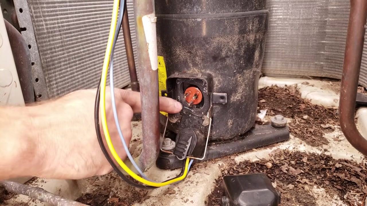
Step 17: Inspect the terminals for damage or corrosion. Examine the plug area for visible damage, corrosion, or wear. Confirm the "C," "R," and "S" labels are legible and that all lugs are intact.
Step 18: Check that the plug fits tightly on the terminals. A properly functioning plug should fit tightly when pushed onto the terminals. A loose fit is a warning sign of a poor connection.
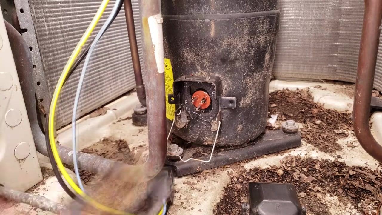
Step 19: Look for missing or damaged lugs. Inspect the terminals for missing or worn lugs, which can indicate melting or electrical damage. A missing or melted lug points to a history of high current or a loose connection.
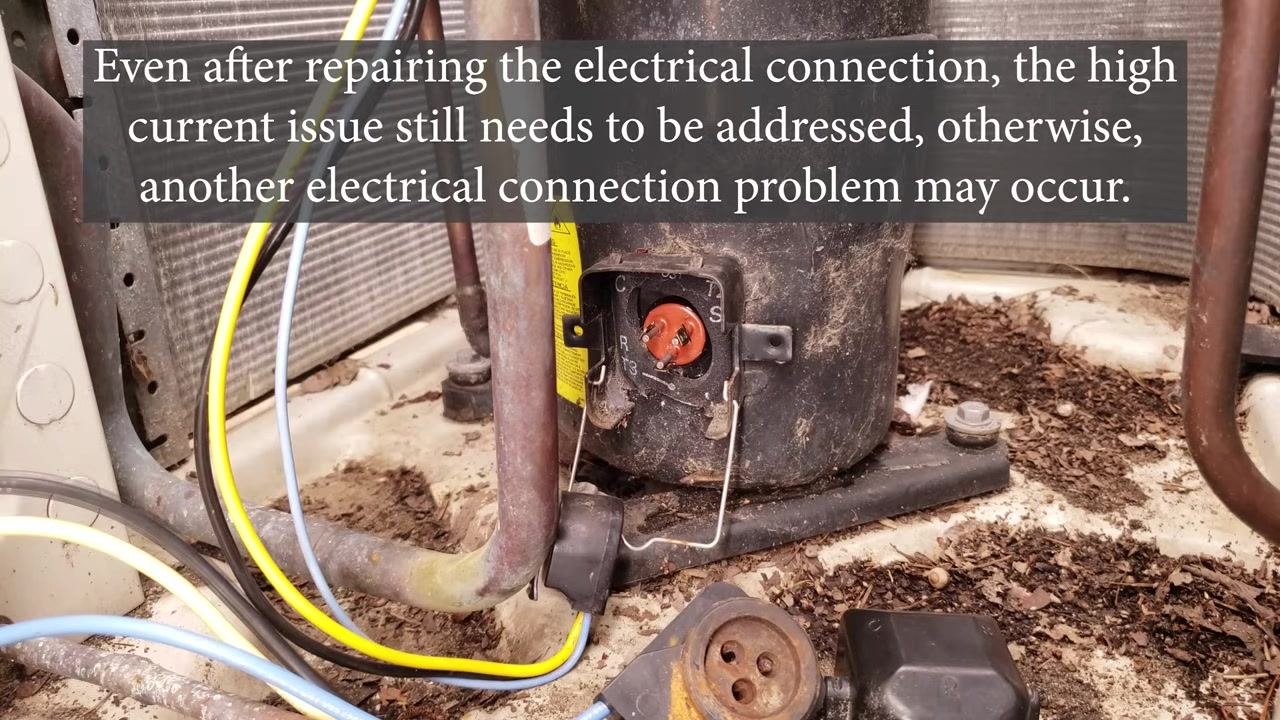
Step 20: Diagnose the underlying cause of terminal damage. Melted or worn lugs are typically caused by excessive current or a poor electrical connection. If you find this kind of damage, investigate the broader electrical system rather than treating the terminal in isolation.
Step 21: Use a compressor lug repair kit only as a temporary fix. If a terminal is damaged, a compressor lug repair kit lets you clamp onto the remaining terminal to restore the connection. This is a temporary solution — the high current issue that caused the damage still needs to be addressed, or the problem may recur.
Step 22: Understand that a repair kit is a last resort. A secure original plug connection is always preferable to a repair kit. Use the kit only when the original plug cannot be restored.
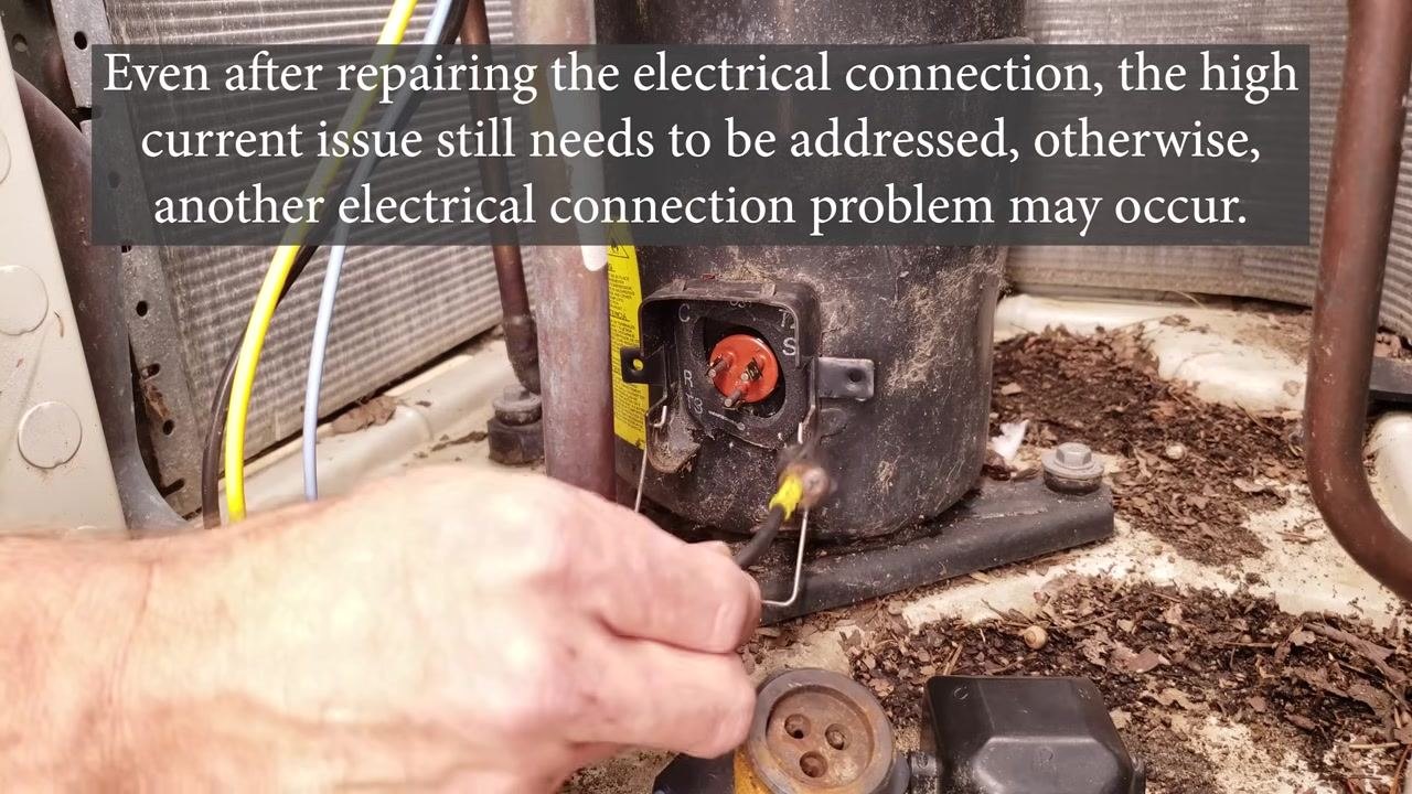
Step 23: Complete a full diagnosis before relying on a repair kit. Always perform a thorough diagnosis to confirm the compressor issue is not simply a faulty plug or terminal. Address the underlying electrical or mechanical problem rather than relying solely on the repair kit.
Step 24: Move on to checking a scroll compressor for a short to ground. As an example, a winding-to-copper-tube measurement of 2 ohms indicates a ground fault on a scroll compressor. Prepare to repeat the ground-fault test on this type of compressor.
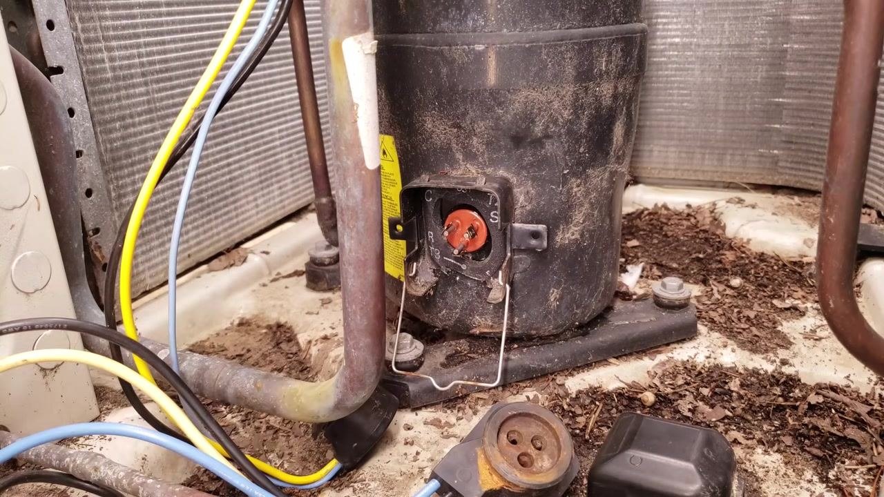
Diagnosing ground shorts and internal burnout
Step 25: Visually inspect the terminals before testing. Look at the exposed terminals labeled "C," "R," and "S," and note any dirt, corrosion, or debris around the compressor base. Identify the removed plug and cover placed nearby before you proceed.
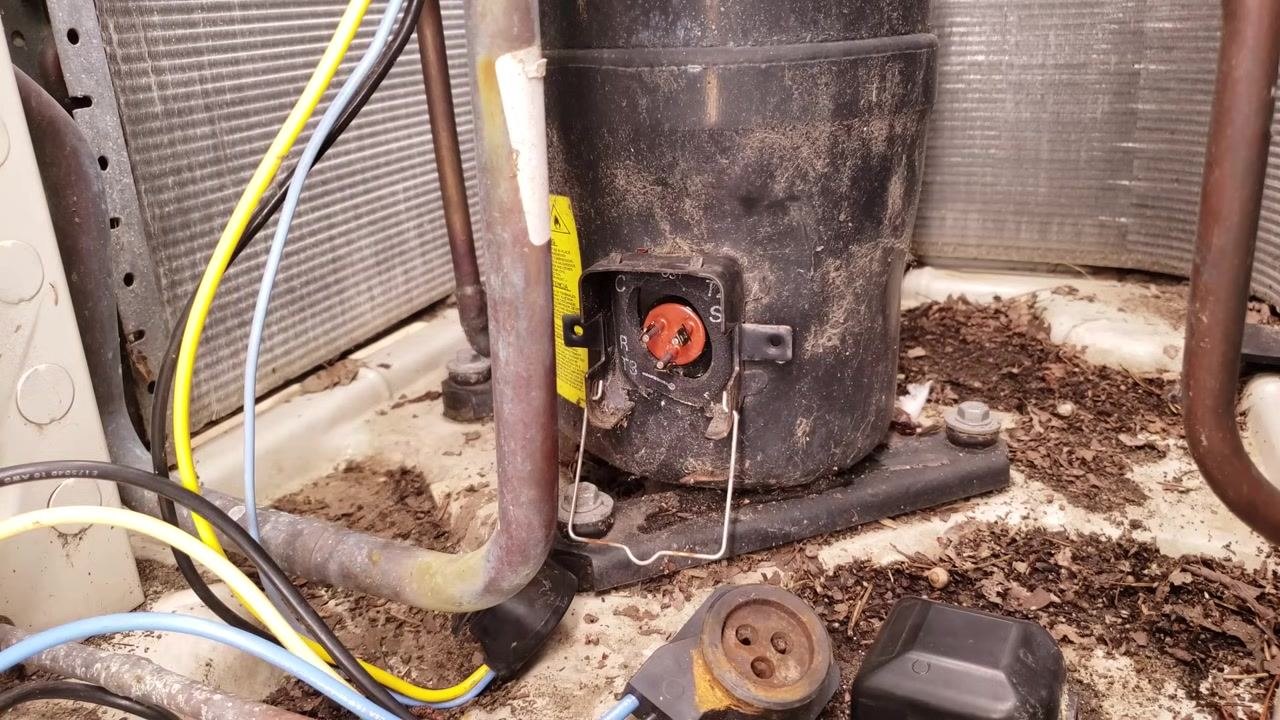
Step 26: Measure resistance between a terminal and ground. Set your multimeter to resistance and attach one probe to a compressor terminal and the other to the copper tube (ground). In this example, the meter shows 2.7 MΩ (megaohms), which checks for a short between the windings and ground.
Step 27: Recognize a short to ground. A resistance reading that is very low, close to zero, indicates a short to ground, which is a serious compressor fault. In this example, the meter alternates and shows 0.000 MΩ at one point.
Step 28: Repeat the measurement to confirm the fault. Take the reading again to confirm your result. In this example, the meter returns to 2.7 MΩ on the repeated test, so compare both readings carefully before concluding whether a short exists.
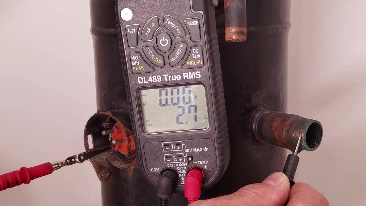
Step 29: Inspect a burned-out compressor internally, if available. Remove the compressor shell to look at the internal windings and rotor. Wear nitrile gloves for safety and cleanliness. Look for burned, blackened, or melted winding insulation, which confirms a burnout.
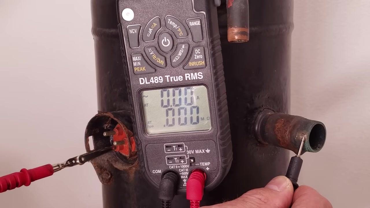
Step 30: Examine the windings and rotor from above. Take a top-down look at the windings and rotor to fully assess the extent of the burnout damage.
Testing a mini-split (three-phase) compressor
Step 31: Test the mini-split compressor for continuity. Connect your multimeter probes to the compressor terminals to measure resistance between pairs on a three-phase mini-split compressor. If there is no continuity, or resistance is very high, the display reads "OL."
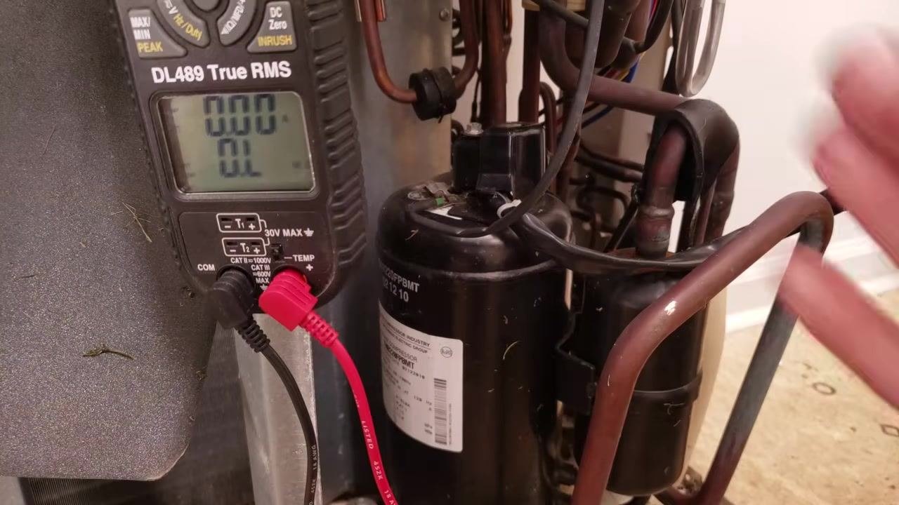
Step 32: Remove the terminal cover. Carefully remove the black plastic terminal cover from the compressor. Note or document the wire positions before you disconnect anything.
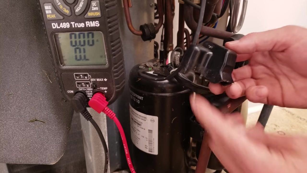
Step 33: Disconnect the compressor wires. Gently pull the wires off the compressor terminals with both hands, keeping the multimeter connected and ready for the resistance measurement.
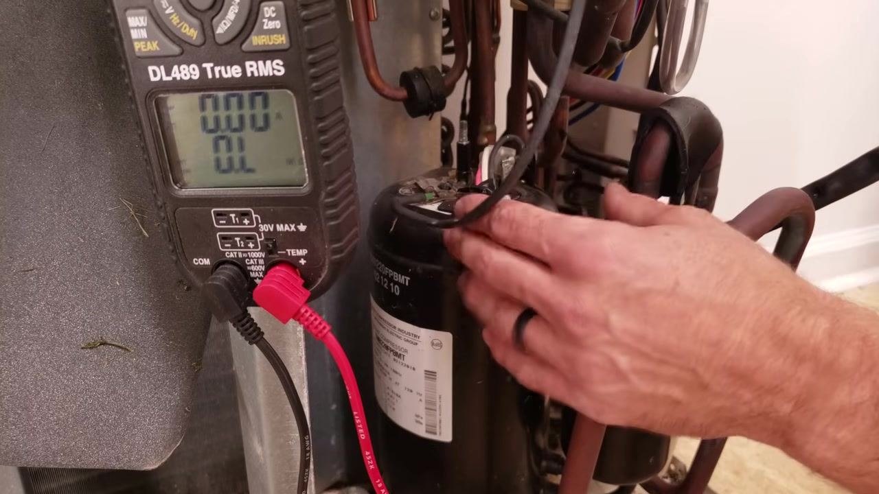
Step 34: Measure resistance between each terminal pair. Set the multimeter to resistance mode and measure between each pair of terminals. In this example, the readings are approximately 1 ohm for each pair (0.3 ohms shown), which indicates normal winding resistance.
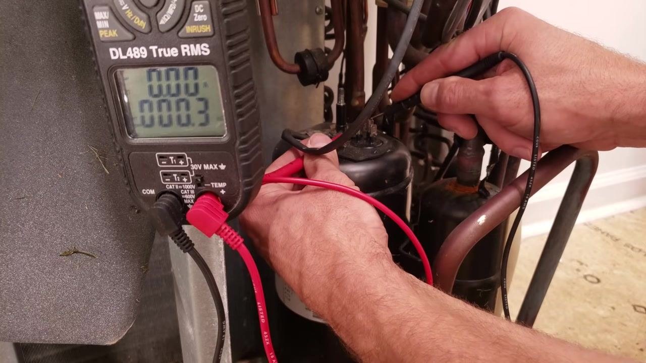
Step 35: Confirm there is no short to ground on the three-phase motor. A healthy three-phase motor shows matching resistance readings between its windings. Place the test leads on the terminals and then check to ground; the display should show "0.00" between windings and "OL" (Open Line) to ground, confirming there is no continuity to ground and the windings are not open.

Verification and summary
Use the following checks to confirm whether an AC compressor is bad:
- Winding resistance between Common-Run, Common-Start, and Start-Run should follow a consistent pattern, with the Start-Run reading approximately equal to the sum of the other two.
- "OL" between Common and both Run and Start, paired with a normal Start-Run reading, points to an open thermal overload rather than a failed winding — let the compressor cool and retest before condemning it.
- A very low resistance reading (near zero) between any terminal and ground indicates a short to ground and confirms a genuine compressor fault.
- Damaged, missing, or melted lugs on the plug terminals point to a high-current or connection problem that must be resolved, not just patched with a repair kit.
- Blackened or melted winding insulation visible after opening the shell confirms a burnout.
- On three-phase motors, matching resistance between windings and an "OL" reading to ground confirms the motor is healthy.
Always ensure the compressor is powered off, isolated, and (if needed) cooled down before performing any of these checks, and use clean, corrosion-free terminal connections for accurate readings.
What's next
Once you've confirmed a compressor is bad using the resistance, ground-fault, and visual inspection steps above, proceed with sourcing a replacement or repair kit as appropriate. For further learning, additional HVAC resources are available:
-
Step 36: Explore the AC Service Tech website for free resources, including an A/C book, articles and tips, tools, a podcast, quizzes, and calculators.
-
Step 37: Access the full video library and additional free educational materials, including quick tips and Q&A content, directly from the website.
-
Step 38: Review the "Refrigerant Charging and Service Procedures for Air Conditioning" book by Craig Migliaccio, available on Google Play Books, for step-by-step HVACR troubleshooting procedures.

- Step 39: Purchase the spiral-bound edition of the book on Amazon for $59.99, along with related quick reference cards and a workbook, or visit www.acservicetech.com for further resources.
Generation details: cost, quality tiers
Docsie billed 6,000 credits ($4.20) to analyze this 12-minute video at standard quality. The rewrite, template fill and Word/PDF exports were included. The same video at each quality tier:
| Quality | Frames sampled | Credits | Approx. cost |
|---|---|---|---|
| Draft | every 16-30 s | 3,000 | $2.10 |
| Standard (this guide) | every 8-15 s | 6,000 | $4.20 |
| Detailed | every 4-7 s | 12,000 | $8.40 |
| Ultra | every 1-3 s | 24,000 | $16.80 |
Credits priced at $0.70 per 1,000; plans include a monthly allowance. Enterprise customers on on-premise or bring-your-own-model deployments run this on their own inference and pay no per-video credits.
Generated by Docsie Video-to-Docs on 2026-09-20 from a 11-minute video. Screenshots are frames from the source video and belong to their creator, AC Service Tech LLC, whose original is embedded above. If you own this video and want the guide removed or credited differently, contact us and we will act within one business day.