
How to Measure Amps with a Multimeter
This procedure explains how to measure amps with a multimeter, along with the related steps for measuring voltage, in a demonstration circuit built from a power supply and parallel pilot lights. It also covers the underlying electrical units—volts, amps, ohms, and watts—so you can interpret your multimeter readings correctly and calculate power consumption.
Video: How To Measure Volts, Amps, Watts, & Ohms with a Multimeter by GalcoTV (2015). All credit for the demonstration goes to the creator; watch the original on YouTube. The written guide below was generated from this video by Docsie. Creator? Request a change or removal.
Purpose
This procedure explains how to measure amps with a multimeter, along with the related steps for measuring voltage, in a demonstration circuit built from a power supply and parallel pilot lights. It also covers the underlying electrical units—volts, amps, ohms, and watts—so you can interpret your multimeter readings correctly and calculate power consumption.
Scope
This procedure applies to measuring voltage and current in a parallel pilot light circuit using a digital multimeter and a regulated DC power supply. It covers preparing the circuit, taking voltage readings, safely reconfiguring the circuit for a current measurement, and calculating power from the results.
Required equipment
- Digital multimeter capable of DC voltage and current measurement (demonstrated with a Fluke 177 True RMS Multimeter)
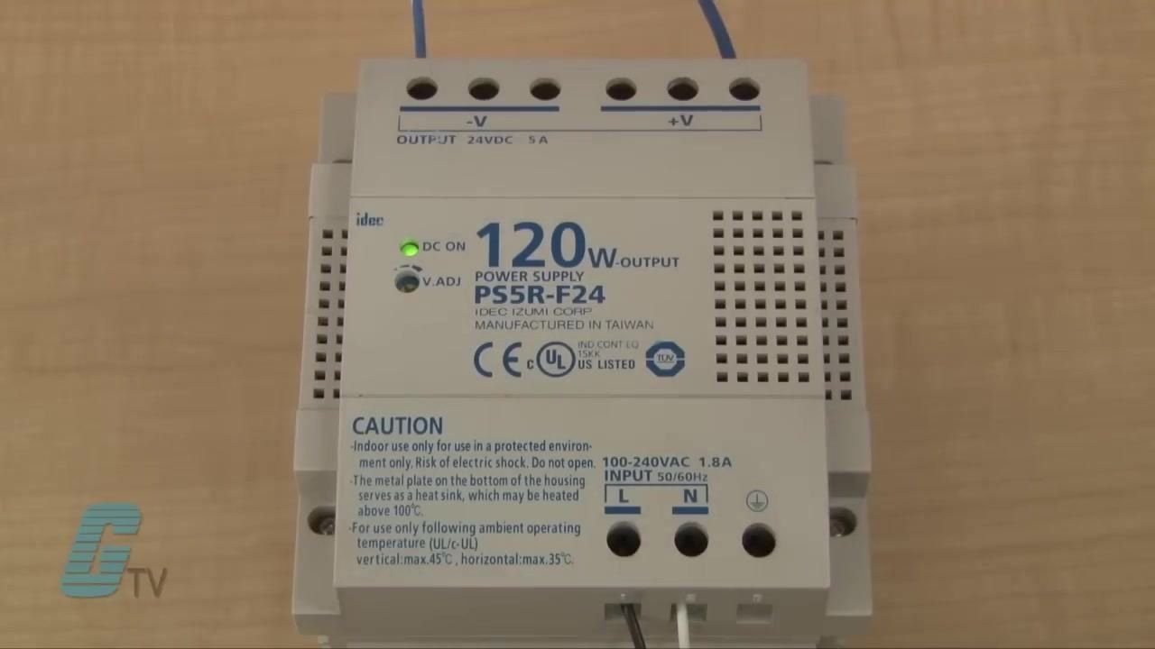
- Regulated DC power supply (demonstrated with an IDEC PS5R-F24, 120 W output, 24 VDC, 5 A)
- Three pilot lights (red, blue, green) wired in parallel
- Selector switch wired to complete the circuit for the pilot lights
- Circuit wiring and terminals
Understand the key electrical units
Before measuring, review the four units you will encounter on the multimeter and in your calculations:
- Volts (V): The unit of electric potential difference, or the force that pushes electrons through a circuit.
- Amps (A): Short for ampere, the unit of electric current, representing the number of electrons flowing through a circuit.
- Ohms (Ω): The unit of electrical resistance, which slows the flow of current in a circuit.
- Watts (W): The unit of power, calculated as the product of current (amps) and voltage (volts). Wattage is the power rating shown on electrical equipment.

These units are related through Ohm's Law:
- Voltage (V) = Current (I) × Resistance (R)
- Current (I) = Voltage (V) ÷ Resistance (R)
- Power (W) = Voltage (V) × Current (I)
For example, light bulbs are rated in watts. A typical bulb may run on a 120-volt supply but draw a comparatively low amp rating—lower wattage means lower current at the same voltage.
Review the demonstration setup
Before taking any measurements, confirm the layout of the circuit:
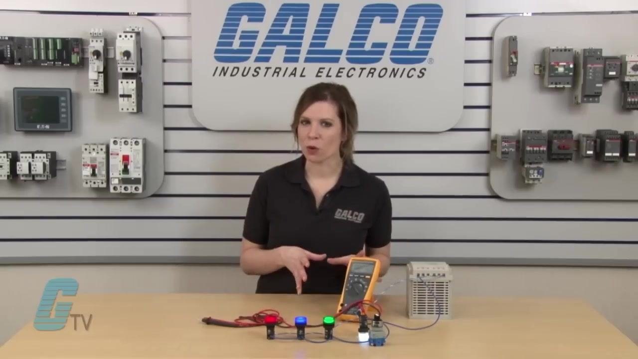
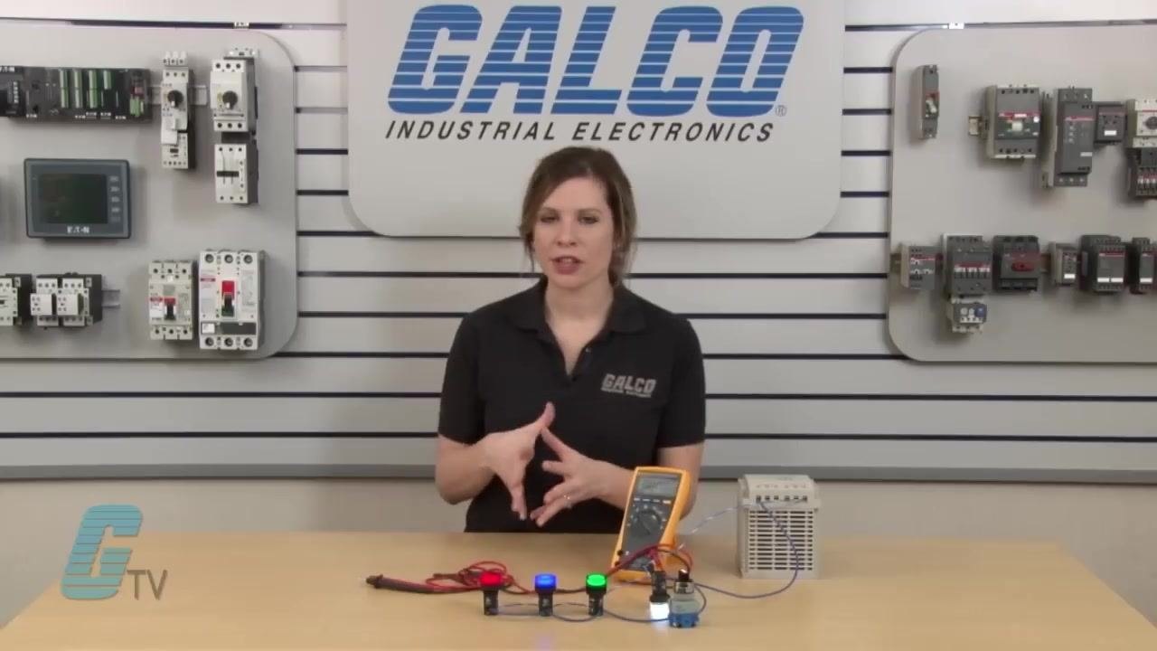
- The setup uses a multimeter, a power supply, and three pilot lights wired in parallel.
- The first pilot light is connected to a selector switch, which completes the circuit for all the lights.
- The first pilot light remains continuously energized throughout the procedure.
- The power supply is set to output 24 volts.
Prepare for measurement
Confirm the following before proceeding:
- The power supply is set to 24 volts.
- The selector switch is completing the circuit for all pilot lights.
- The first pilot light is continuously energized.
Measure voltage with the multimeter
- Place the multimeter probes across the terminals of the last pilot light in the parallel circuit.
- Observe the voltage reading on the multimeter display; it should show approximately 24 volts.
- This confirms that each parallel branch receives the full supply voltage.
Turn off the selector switch
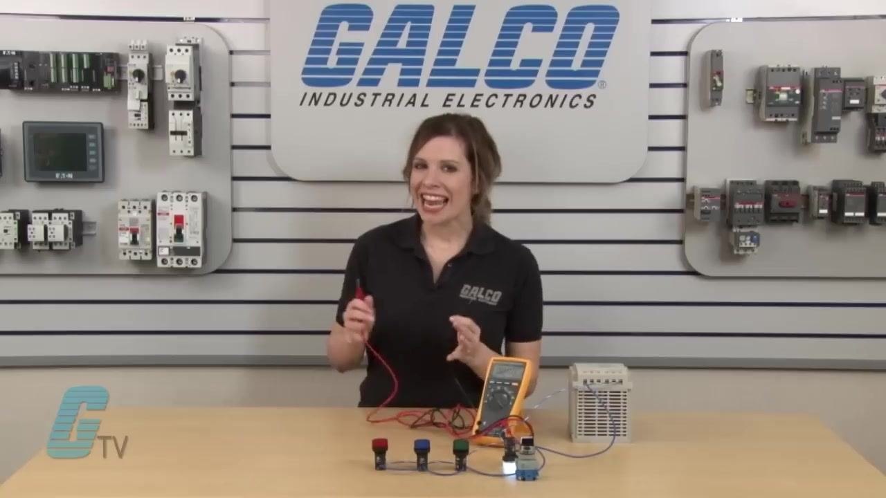
Rotate the selector switch to the off position to disconnect the circuit for all pilot lights except the first, which remains energized. Measure the voltage on the remaining energized pilot light to confirm it still reads 24 volts.
Prepare to measure current
Current is drawn by the load and must be measured in series with the circuit, unlike voltage, which is measured in parallel. Some applications draw more current than others, which is why the meter must be placed in line with the load rather than across it.
Turn off the power supply
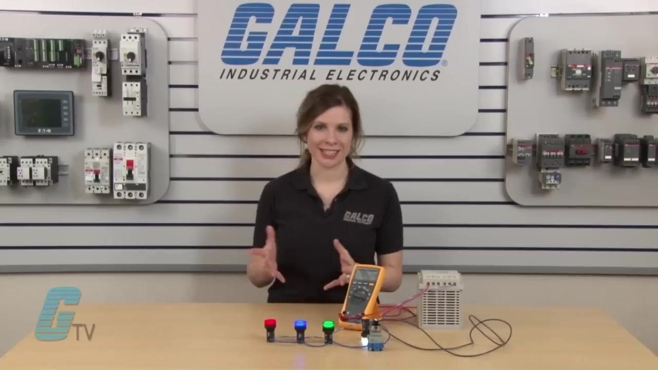
Safety note: Always switch off the power supply before modifying any circuit connections.
Locate the power supply (demonstrated with an IDEC PS5R-F24, 120 W output, 24 VDC, 5 A) and switch it off so the circuit can be safely reconfigured.
Disconnect the line to the pilot light
Remove the wire leading to the pilot light where current will be measured. This creates the opening needed to insert the multimeter in series with the load.
Connect the multimeter for current measurement
- Attach one end of the disconnected wire to one lead of the multimeter.
- Connect the other lead of the multimeter to the terminal of the pilot light.
- Insert the multimeter leads into the correct ports for amperage measurement:
- Red lead in the 10A port.
- Black lead in the COM port.
Set the multimeter to measure amps
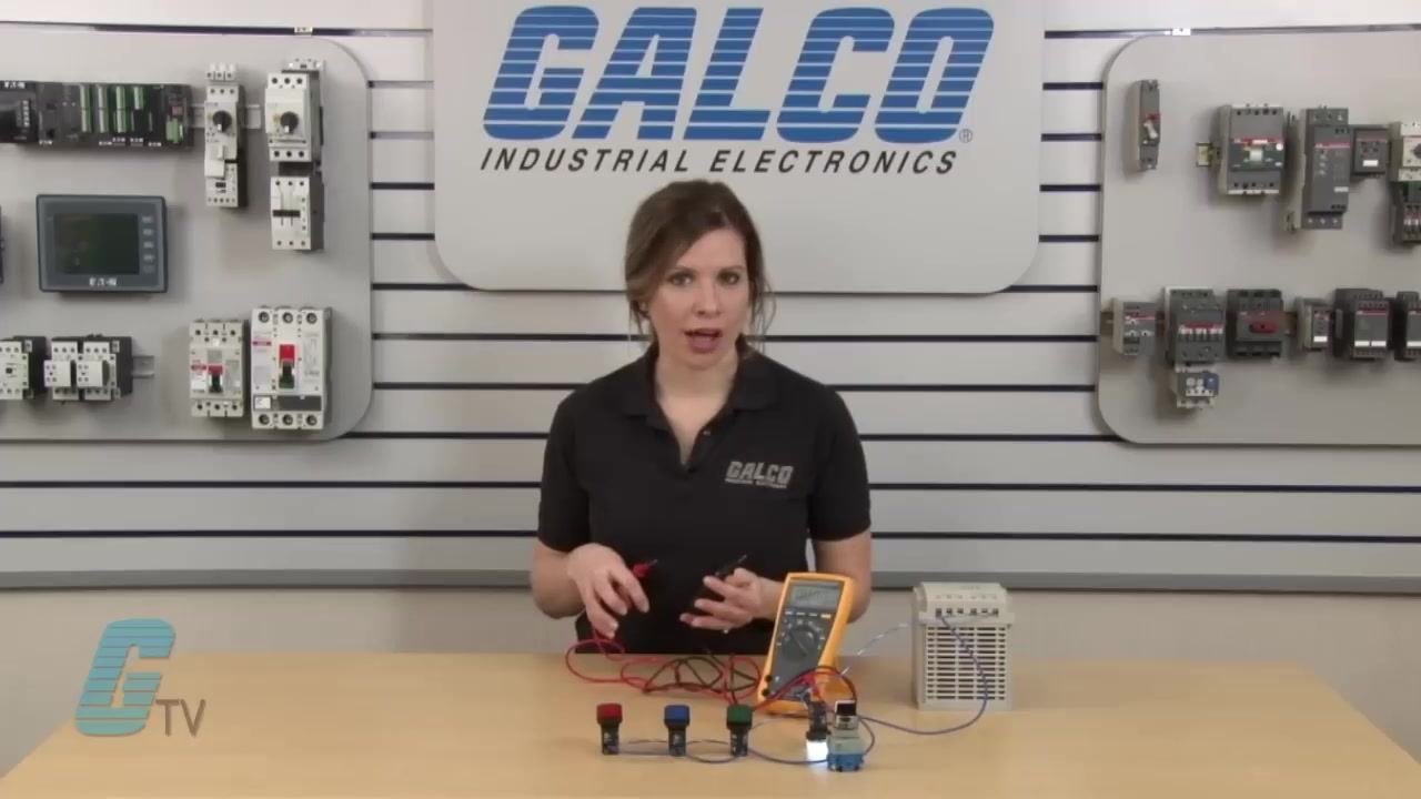
Turn the multimeter dial to the highest current (A) setting—A4 or 10A, depending on your model. Starting at the highest range prevents damage to the multimeter if the actual current is higher than expected.
Reapply power and measure current
- Turn the power supply back on.
- Read the current value on the multimeter display.
In this demonstration, the multimeter reads 0.014 A (14 mA) DC.
Turn on the selector switch for all loads
Activate the selector switch to energize all pilot lights. Watch the current reading on the multimeter increase, reflecting the total current drawn by all parallel loads.
Calculate power consumption
Use the measured current and the known supply voltage (24 V) to calculate the total power consumed by the circuit:
- Multiply the current value by 24 volts to obtain the wattage.
- Example: If the current is 0.014 A, then Power (W) = 24 V × 0.014 A = 0.336 W.
Verification and summary
You have now measured both voltage and current in a parallel pilot light circuit using a multimeter, and calculated the resulting power consumption. Confirm the following before closing out the procedure:
- Voltage readings across the pilot lights matched the 24-volt supply.
- The multimeter was placed in series with the load for the current reading, using the correct input ports.
- The measured current was used with the supply voltage to calculate wattage.
Always turn off power before modifying circuit connections, and always start a current measurement on the highest available range on your multimeter.
What's next
For additional products, technical resources, and support related to multimeters, power supplies, and pilot lights, visit galco.com.

Generation details: cost, quality tiers
Docsie billed 2,000 credits ($1.40) to analyze this 4-minute video at standard quality. The rewrite, template fill and Word/PDF exports were included. The same video at each quality tier:
| Quality | Frames sampled | Credits | Approx. cost |
|---|---|---|---|
| Draft | every 16-30 s | 1,000 | $0.70 |
| Standard (this guide) | every 8-15 s | 2,000 | $1.40 |
| Detailed | every 4-7 s | 4,000 | $2.80 |
| Ultra | every 1-3 s | 8,000 | $5.60 |
Credits priced at $0.70 per 1,000; plans include a monthly allowance. Enterprise customers on on-premise or bring-your-own-model deployments run this on their own inference and pay no per-video credits.
Generated by Docsie Video-to-Docs on 2026-09-20 from a 3-minute video. Screenshots are frames from the source video and belong to their creator, GalcoTV, whose original is embedded above. If you own this video and want the guide removed or credited differently, contact us and we will act within one business day.