
How to Use Stiffener in CATIA
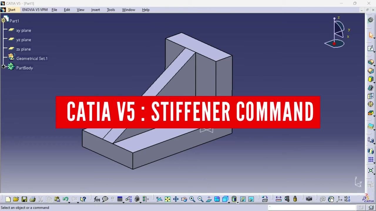
The Stiffener command adds a rib or stringer to a part or wall. It increases the part's strength without breaking the part. This guide shows you how to use stiffener in CATIA V5 in two scenarios: between two flat surfaces, and between a flat surface and a round surface.
Video: How to use stiffener command in catia v5 | stiffener in catia v5 | catia v5 tutorial by Design with Sairaj (2024). All credit for the demonstration goes to the creator; watch the original on YouTube. The written guide below was generated from this video by Docsie. Creator? Request a change or removal.
The Stiffener command adds a rib or stringer to a part or wall. It increases the part's strength without breaking the part. This guide shows you how to use stiffener in CATIA V5 in two scenarios: between two flat surfaces, and between a flat surface and a round surface.
Prerequisites
- CATIA V5 with access to the Part Design workbench
- Basic familiarity with sketching, such as drawing profiles and applying constraints
Scenarios covered
- Both surfaces are flat.
- One surface is flat and the other is round.
Create a stiffener between two flat surfaces
In this scenario, you create a pad, sketch a line across it, and use that line to build the stiffener.
Step 1: Open the Part Design workbench
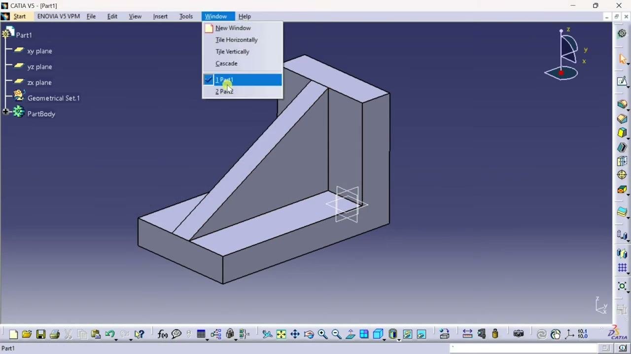
Open the Part Design workbench in CATIA V5. You see the default interface, with the model tree on the left and the 3D workspace in the center.
Step 2: Make PartBody the active work object
Before sketching, right-click PartBody in the model tree and select Define In Work Object. This ensures all new features are added to the correct part body.
Step 3: Start a sketch on a plane
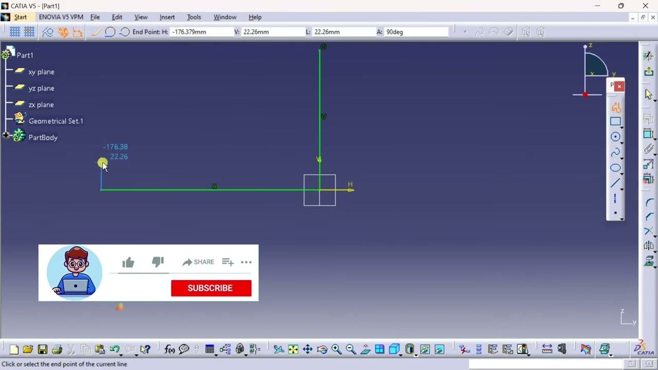
Click the Sketch command and select a plane (xy, yz, or zx). The selected plane is highlighted, and the sketching grid appears in the workspace.
Step 4: Draw the profile
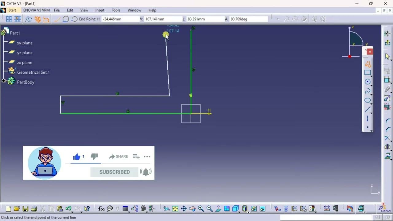
Use the Profile command to draw the sketch on the selected plane. Draw lines as needed to define the profile. The interface displays coordinates and dimensions as you draw.
Step 5: Exit the sketch
Press Esc, then click Exit Workbench to return to the main modeling environment. The sketch is saved and ready to use.
Step 6: Select the sketch for the pad
Click the Pad command in the Part Design workbench. In the Pad Definition dialog, click the Selection box under Profile/Surface. Select your sketch in the workspace or model tree. The selected sketch is highlighted.
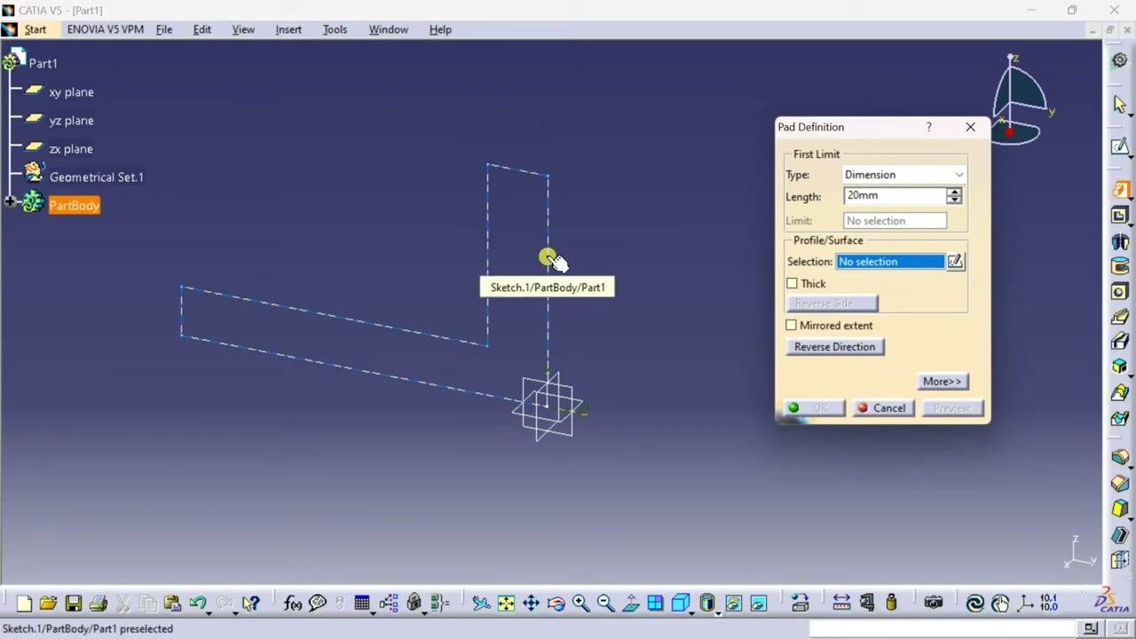
Step 7: Set the pad length and mirrored extent
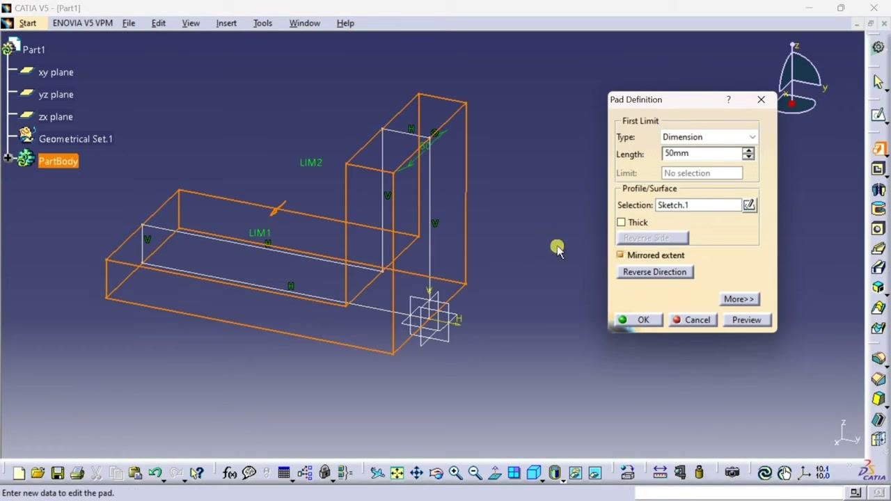
In the Length field, enter the pad length, for example 50 mm. To extend the pad equally in both directions from the sketch plane, check Mirrored extent. The preview shows the pad extending equally on both sides of the sketch plane.
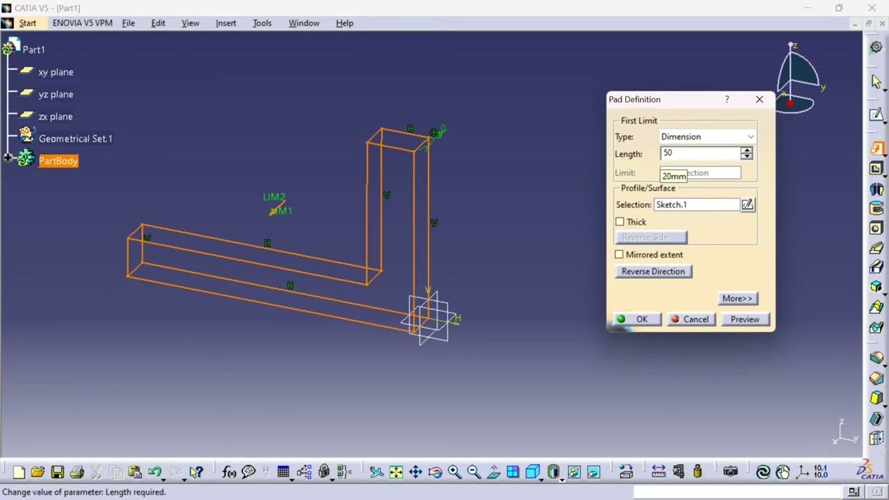
Step 8: Create the pad
Click Preview to check the result, then click OK. The 3D model updates to show the new solid feature.
Step 9: Sketch the stiffener line
Click the Sketch command and select the plane or planar face you want on your model. Click the Line tool in the sketch toolbar, then click the start and end points of your stiffener line. Press Esc to stop the line command.
Step 10: Open the Constraint command
Constrain the line so that it is fully defined. Click the Constraint command in the sketch toolbar.
Step 11: Apply coincidence constraints
Right-click an endpoint of the line and select Coincidence from the context menu. Then select the edge of the sketch or model that you want to attach the line to. Repeat for the other endpoint as needed.
When the line turns green, it is fully constrained and fixed in position.
Step 12: Exit the sketch and open the Sketch-Based Features toolbar
Click Exit Workbench to leave the sketch environment and return to the Part Design workbench. Make sure the line is ready to use as the stiffener profile.
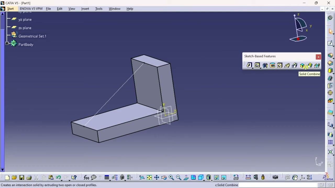
Locate the Sketch-Based Features toolbar. If necessary, drag it to a convenient place on your screen.
Step 13: Access the Stiffener command
This step is the starting point for how to use stiffener in CATIA V5. In the Sketch-Based Features toolbar, click the Solid Combine icon. Click the small arrow next to it to expand more options, then select Stiffener from the dropdown.
Step 14: Select the stiffener profile
In the Stiffener Definition dialog, go to the Profile section and click the Selection box. Click the line you drew, for example Sketch.2/PartBody/Part1. The selected line is highlighted in the 3D view.
Step 15: Set the stiffener thickness
In the Stiffener Definition dialog, set these values:
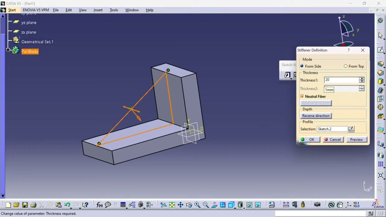
- Set Thickness1 to 20mm.
- Set Thickness2 to 0mm, if it is not already set.
- Check Neutral Fiber to distribute the thickness equally on both sides of the profile, similar to the Mirrored extent option.
Optionally, adjust the Mode (From Side or From Top) and the Depth.
Step 16: Preview and create the stiffener
Click Preview in the Stiffener Definition dialog to see the stiffener. If you are satisfied, click OK. The 3D model updates to show the new stiffener connecting the two flat surfaces.
Create a stiffener between a flat and a round surface
In this scenario, you extrude a circle and a rectangle with Multi-Pad, then add a stiffener between the resulting cylinder and the rectangle.
Step 17: Open a new part
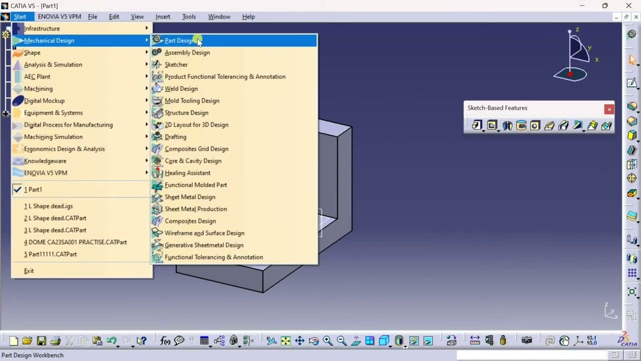
Click Start in the top menu and go to Mechanical Design > Part Design. In the New Part dialog, enter a name for your part, for example "Part2". Keep the default options (Enable hybrid design, Create a geometrical set) as needed, then click OK.
Step 18: Prepare the new part for sketching
In the new part, right-click PartBody in the tree and select Define In Work Object. This makes PartBody the active work object.
Step 19: Remove unwanted sketches
If an unwanted sketch exists on the selected plane, right-click it and delete or clear it before you continue. The next steps use a sketch that contains a circle and a rectangle.
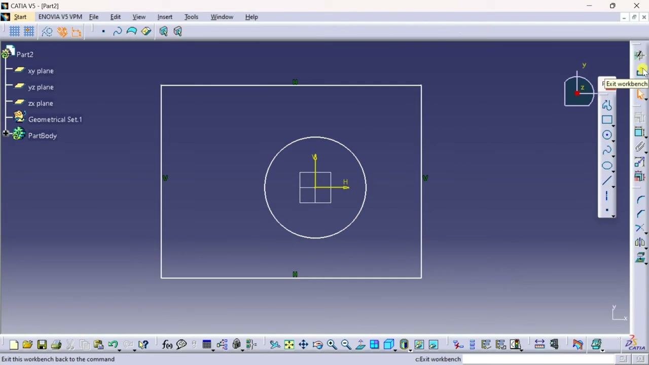
Step 20: Exit the sketch workbench
Click the Exit workbench icon on the right toolbar. This returns you to the main Part Design workbench. The rectangle and circle remain visible.
Step 21: Start the Multi-Pad feature
In the Sketch-Based Features toolbar, click the Multi-Pad icon. This lets you create extrusions from multiple domains in the sketch.
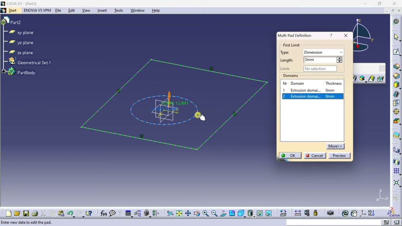
Step 22: Select the circle as a domain
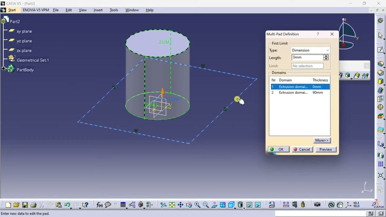
In the Multi-Pad Definition dialog, click the circle in the sketch. The circle turns blue, and the domain list in the dialog updates to show the selection.
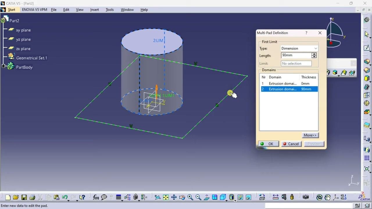
Step 23: Set the circle's extrusion length
Set Length for the circle domain to 90mm. The preview shows a cylinder extruded from the circle.
Step 24: Select the rectangle as a domain
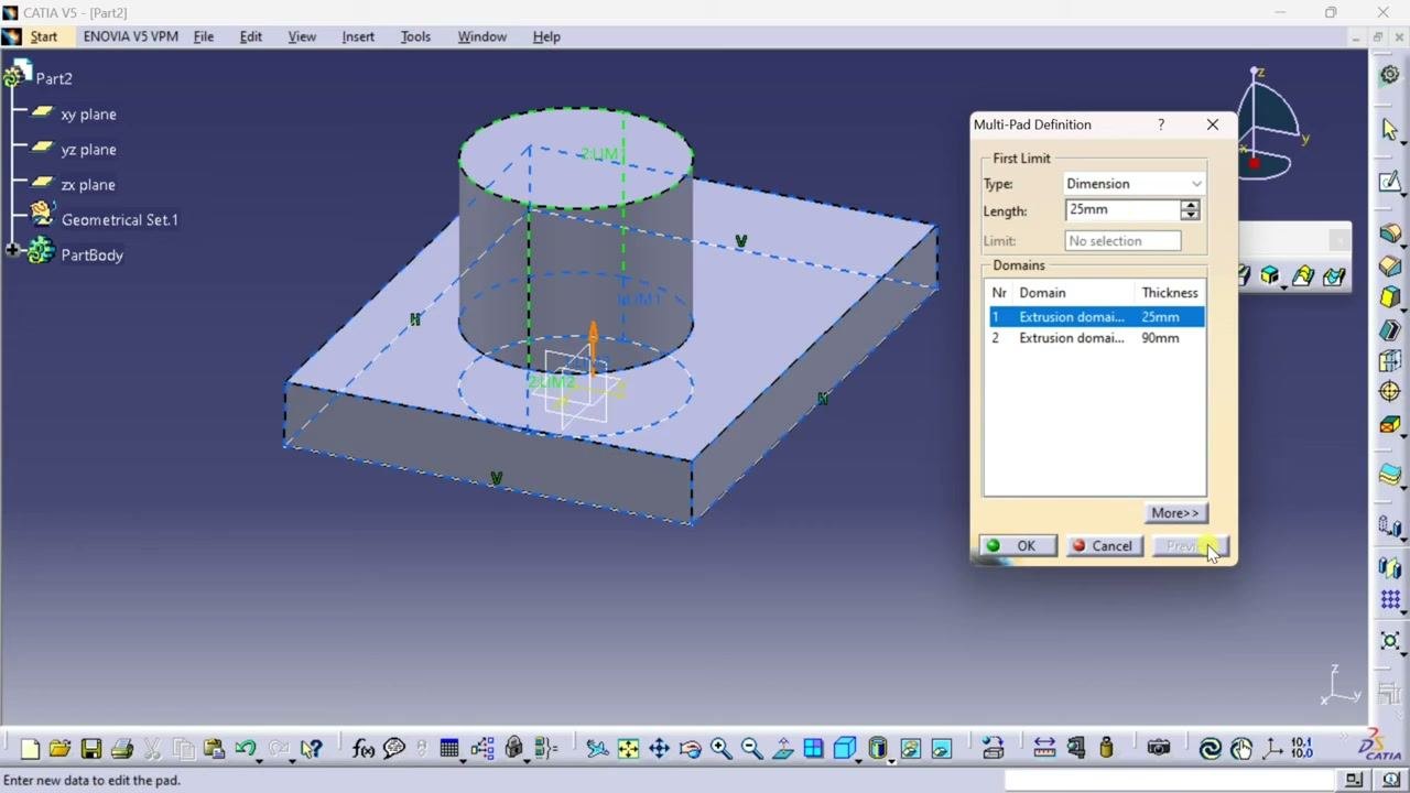
Click the rectangle in the sketch. The rectangle turns blue, and the domain list updates to show it as a domain.
Step 25: Set the rectangle's extrusion length
Set Length for the rectangle domain to 25mm. The preview shows both the cylinder and the extruded rectangle. Click OK to apply the Multi-Pad operation.
Step 26: Create a new sketch
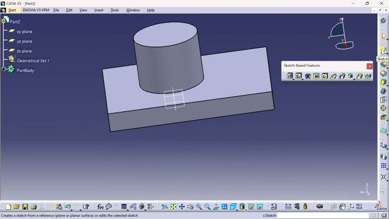
In the Sketch-Based Features toolbar, click the Sketch icon. The model is ready for a new sketch on a selected face or plane.
Step 27: Select the rectangle's face
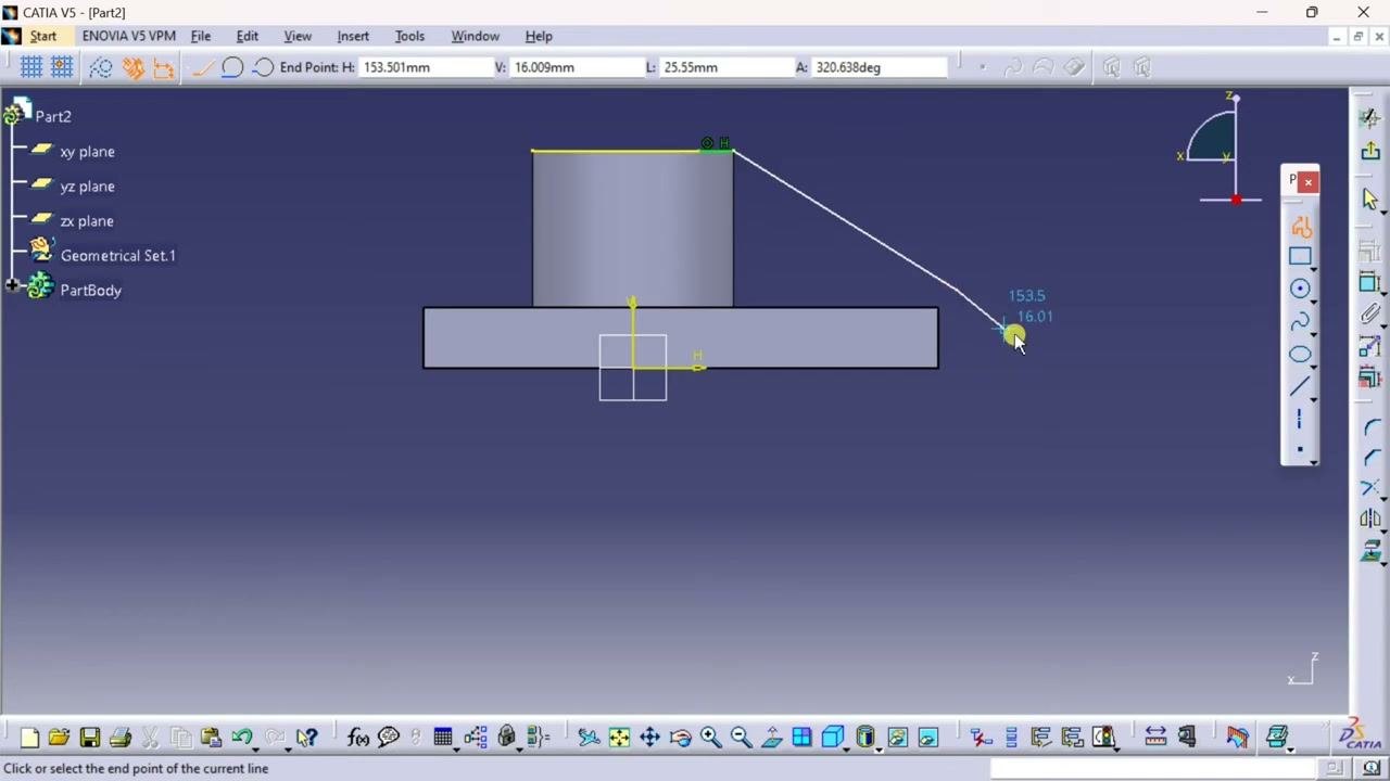
In the side view, position the cursor over the top face of the rectangle and select it. Coordinate values appear for the selected point.
Step 28: Project 3D elements as reference lines
Use the Project 3D Elements command to project edges from the 3D model onto the sketch plane. These reference lines help you position new sketch elements accurately.
Step 29: Draw the stiffener line
Draw a diagonal line from the top right of the cylinder to the lower right of the rectangle. The line is white, with endpoints highlighted in green and blue. At the lower endpoint, the status bar shows "End Point: H 153.501mm V 16.009mm L 25.55mm A 320.638deg". You are still in the sketcher workbench, and the line is ready to be constrained.
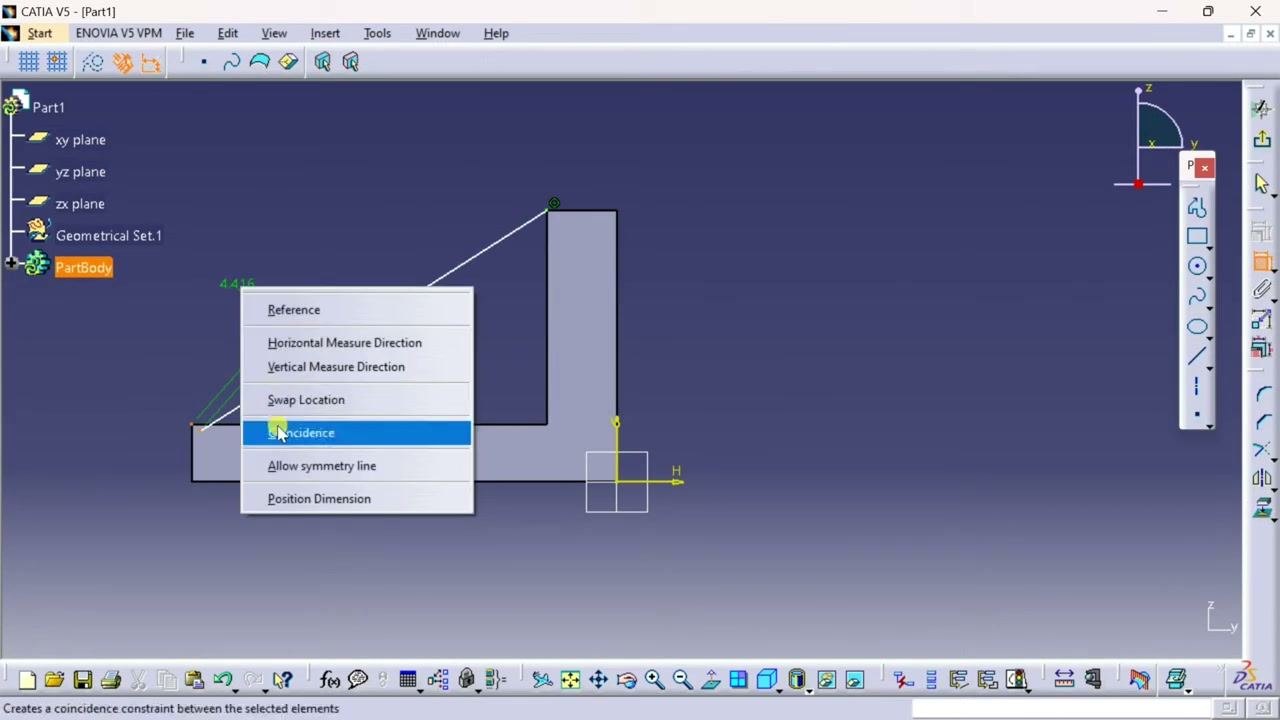
Step 30: Apply a coincidence constraint
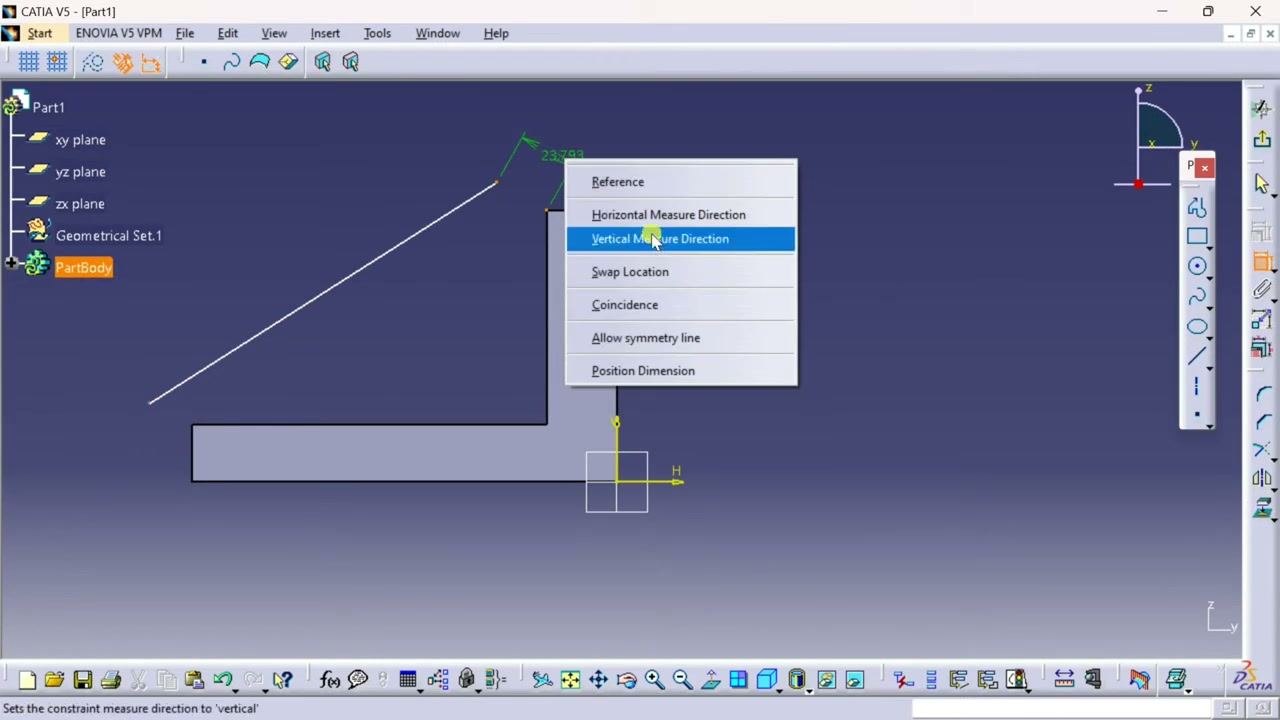
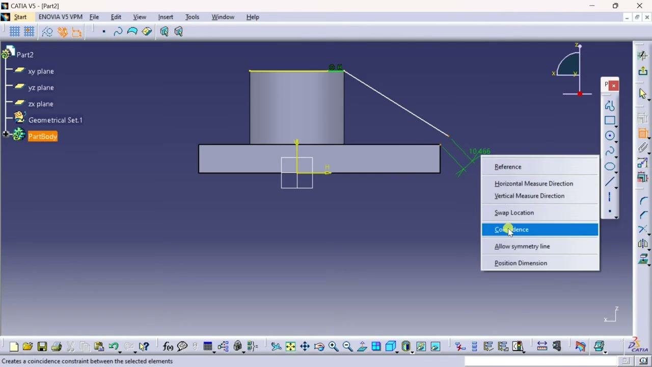
Right-click an endpoint of the line to open the context menu. It lists Reference, Horizontal Measure Direction, Vertical Measure Direction, Swap Location, Coincidence, Allow symmetry line, and Position Dimension. Select Coincidence to constrain the endpoint to the selected reference.
Step 31: Convert the line to a construction element
Click the Construction/Standard Element button in the top toolbar. The diagonal line turns green, which shows it is now a construction element. The model stays in the side view, with the construction line visible.
Step 32: Activate the Stiffener command
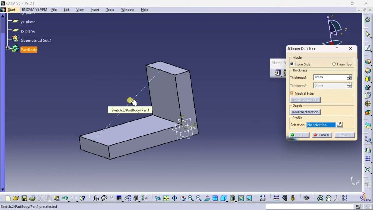
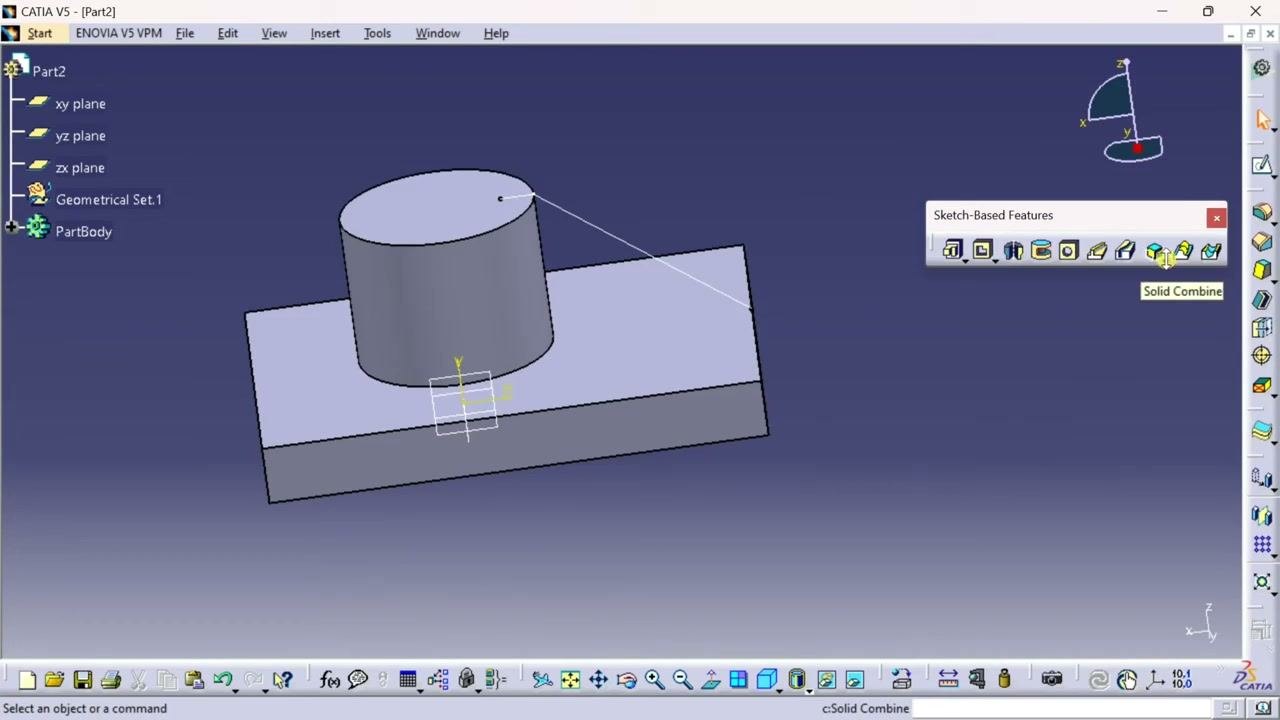
Exit the sketch so the model is shown in isometric view with the construction line visible. In the Sketch-Based Features toolbar, click the arrow next to Solid Combine, then click the Stiffener command. This is the second scenario for how to use stiffener in CATIA V5.
Step 33: Select the sketch line as the profile
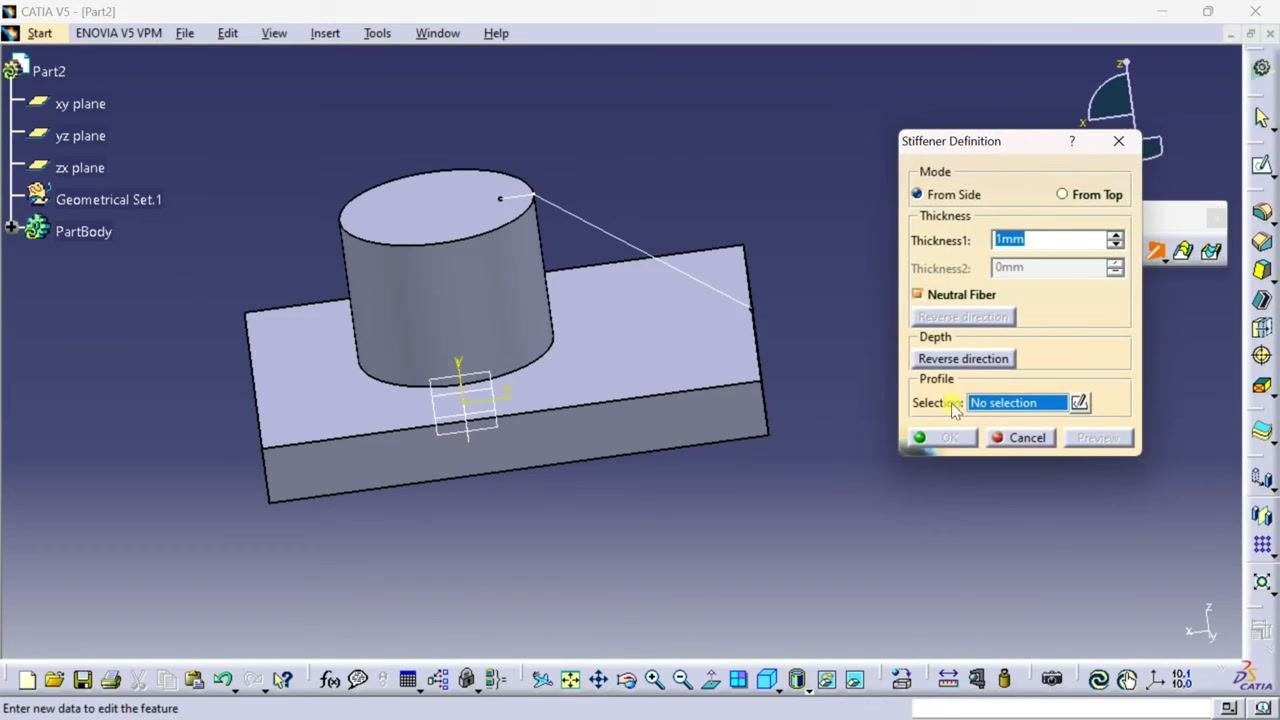
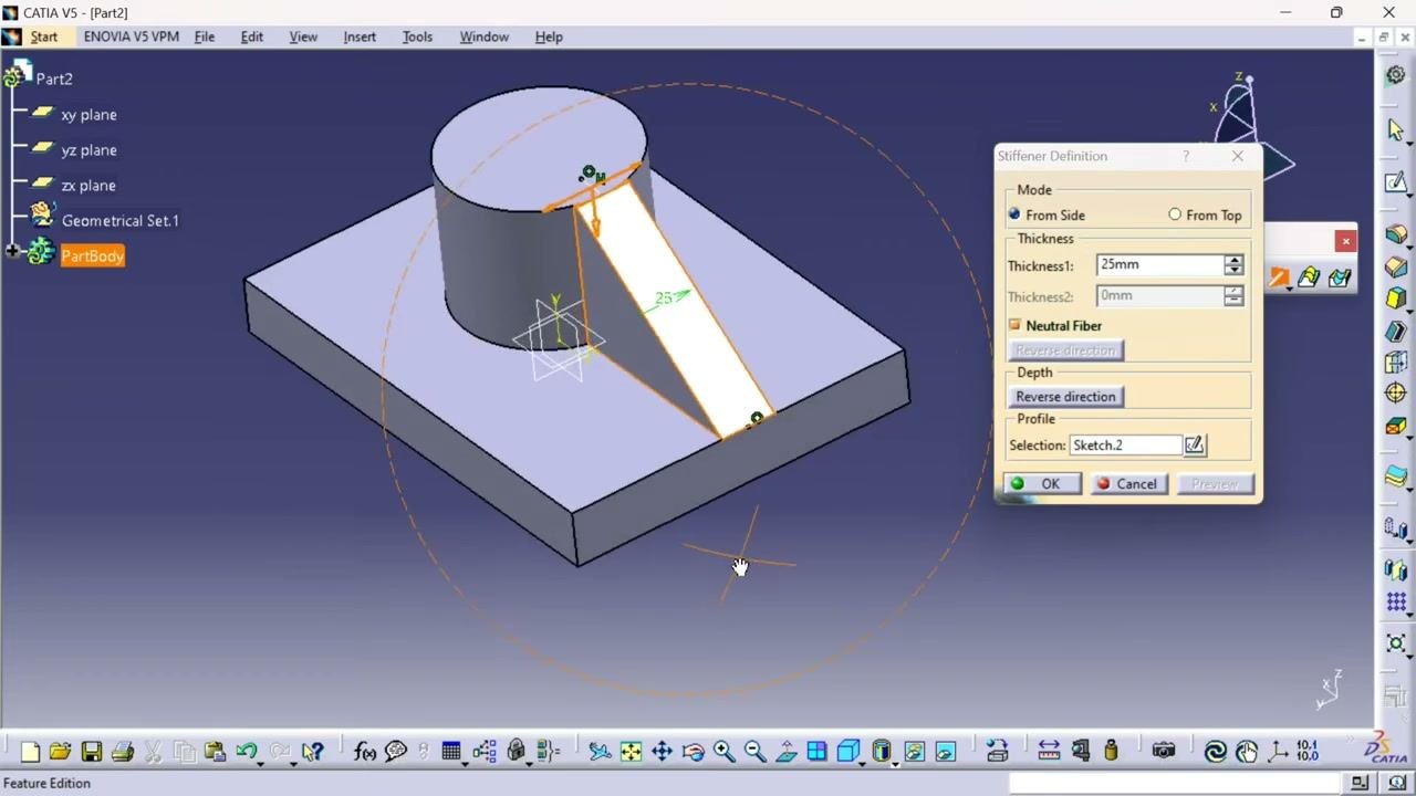
The Stiffener Definition dialog appears on the right. By default, Mode is From Side, Thickness1 is 1mm, Thickness2 is 0mm, and Neutral Fiber is checked. The Profile section shows "No selection". Select the sketch line as the profile.
Step 34: Set the thickness values
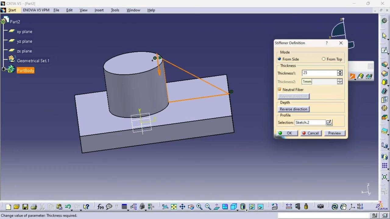
With the profile selected, the model shows the cylinder on top of the rectangle and an orange construction line connecting them. An orange arrow indicates the direction of the stiffener. Confirm these settings in the dialog:
- Mode: From Side
- Thickness1: 25mm
- Thickness2: 0mm
- Neutral Fiber: Checked
- Profile: Sketch.2
With Neutral Fiber checked, the thickness is distributed equally on both sides of the selected sketch line.
Step 35: Preview and confirm the stiffener
The model now displays the stiffener as a solid feature between the cylinder and the rectangle, following the construction line. The stiffener is highlighted in a light color, and the dimension "25" appears along it to show its thickness. The dialog stays open with your settings. Click OK to finish.
Summary
You now know how to use stiffener in CATIA V5 for both scenarios. For two flat surfaces, you create a pad, sketch and constrain a line, and apply the Stiffener command with a thickness and Neutral Fiber. For a flat and a round surface, you use Multi-Pad to extrude a circle and a rectangle, project 3D references, draw a construction line, and build the stiffener from it. In both cases, the Neutral Fiber option distributes the stiffener thickness equally on both sides of the profile.
Generation details: cost, quality tiers
Docsie billed 4,500 credits ($3.15) to analyze this 9-minute video at standard quality. The rewrite, template fill and Word/PDF exports were included. The same video at each quality tier:
| Quality | Frames sampled | Credits | Approx. cost |
|---|---|---|---|
| Draft | every 16-30 s | 2,250 | $1.57 |
| Standard (this guide) | every 8-15 s | 4,500 | $3.15 |
| Detailed | every 4-7 s | 9,000 | $6.30 |
| Ultra | every 1-3 s | 18,000 | $12.60 |
Credits priced at $0.70 per 1,000; plans include a monthly allowance. Enterprise customers on on-premise or bring-your-own-model deployments run this on their own inference and pay no per-video credits.
Generated by Docsie Video-to-Docs on 2026-11-15 from a 8-minute video. Screenshots are frames from the source video and belong to their creator, Design with Sairaj, whose original is embedded above. If you own this video and want the guide removed or credited differently, contact us and we will act within one business day.