
How to Use Multi-section Solid in CATIA
This guide shows you how to use multi-section solid in CATIA V5. You start with two circular sections, then move to sections with different profiles, such as a circle and a triangle. You then control the result with coupling modes, a spine curve, and guide curves. By the end, you have built a curved solid and compared it with a reference image.
Video: CATIA V5 Multi Section Solid | Coupling modes - FULL tutorial by MechStuff (2021). All credit for the demonstration goes to the creator; watch the original on YouTube. The written guide below was generated from this video by Docsie. Creator? Request a change or removal.
This guide shows you how to use multi-section solid in CATIA V5. You start with two circular sections, then move to sections with different profiles, such as a circle and a triangle. You then control the result with coupling modes, a spine curve, and guide curves. By the end, you have built a curved solid and compared it with a reference image.
Prerequisites
- CATIA V5 is installed and open on the main application window.
- You know how to open the Sketcher workbench and draw basic shapes such as circles, lines, and triangles.
When CATIA V5 starts, you see a starry background with the title bar and the standard menu options (Start, File, Edit, View, Insert, Tools, Window, Help). No part or model is open yet.
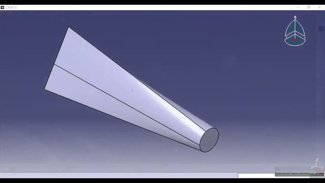
Understand padding and multi-section solid
Step 1. Compare padding with a multi-section solid
Before you build the model, review how the two features differ:
- Padding: Between any two sections, the cross-sectional area and the profile stay the same along the whole length.
- Multi-section solid: The cross-sectional area and the profile can be completely different from one section to the next.
The comparison shows two 3D models. The "Padding" model is a cylinder with the same cross-section throughout. The "Multi-section solid" model is a tapered or morphing solid with different cross-sections.
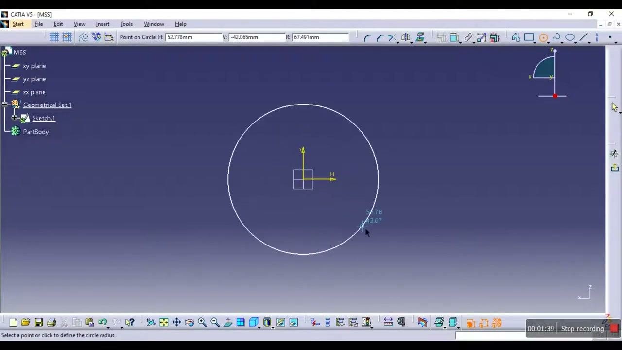
Set up the part and the first two sections
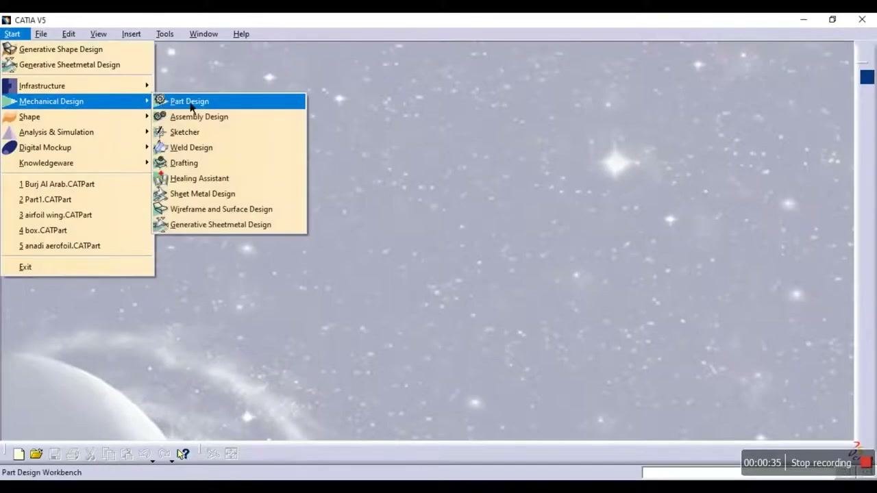
Step 2. Open the Part Design workbench
- Open the Start menu.
- Go to Mechanical Design.
- Select Part Design from the list.
The Part Design workbench opens.
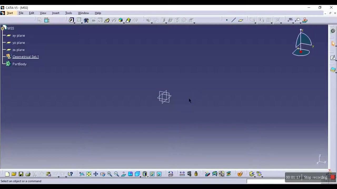
Step 3. Rename the part and review the workbench
Rename the file MSS (Multi Section Solid) so it is easy to identify.
The tree on the left shows the part name (MSS), the standard planes (xy, yz, zx), Geometrical Set.1, and PartBody. The main workspace is empty and ready for sketching.
Step 4. Select the ZX plane
Start with a simple sketch using the default settings.
- Select the ZX plane in the tree on the left.
- Enter the Sketcher workbench.
Step 5. Draw the first circle
- Draw a circle on the ZX plane.
- Set the radius to 60 mm.
- Complete the sketch and exit the Sketcher workbench.
Step 6. Create an offset plane for the second section
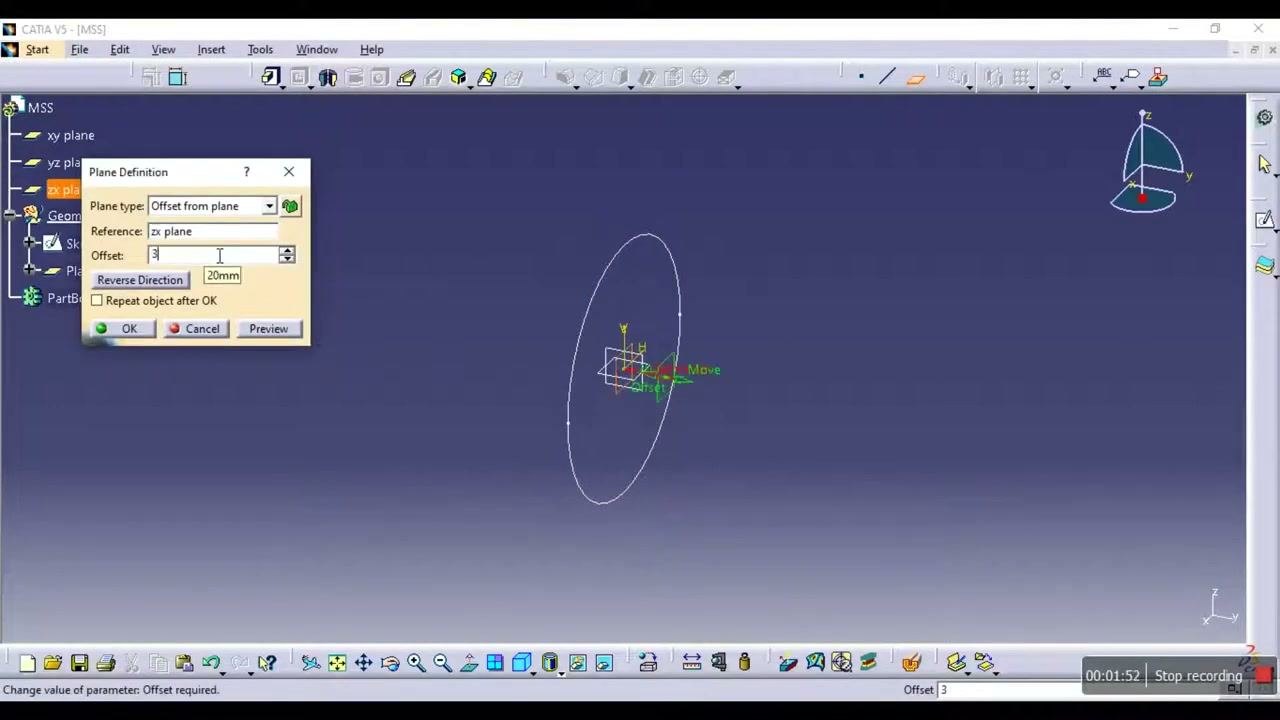
- Open the Plane Definition dialog.
- Set Plane type to "Offset from plane".
- Set Reference to "zx plane".
- Enter Offset as 300 mm. If needed, use "Reverse Direction" to flip the offset.
- Click OK to create the new plane.
Step 7. Draw a smaller circle on the offset plane
- Make sure you are working on the new offset plane (Plane.1).
- Enter the Sketcher workbench.
- Draw a circle with a radius of 20 mm.
- Complete the sketch and exit the Sketcher workbench.
Create a multi-section solid between two circles
Step 8. Use the Multi-Section Solid command
Now use multi-section solid in CATIA V5 with the two circles.
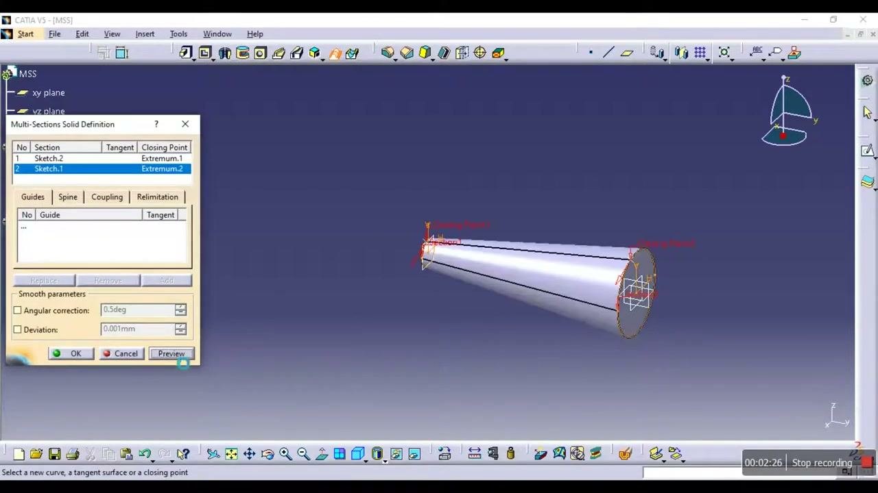
- Start the Multi-Section Solid command.
- In the Multi-Sections Solid Definition dialog, choose the first section as the smaller circle (Sketch.2).
- Choose the second section as the larger circle (Sketch.1).
- Click Preview to visualize the solid.
The solid transitions from a small circle to a large circle. The cross-sectional areas differ, but the profile stays the same (concentric circles).
Step 9. Review the generated solid
Rotate and inspect the solid to confirm the transition between the two circular sections. The cross-sectional area changes, but the profile remains circular throughout.
Use different section profiles
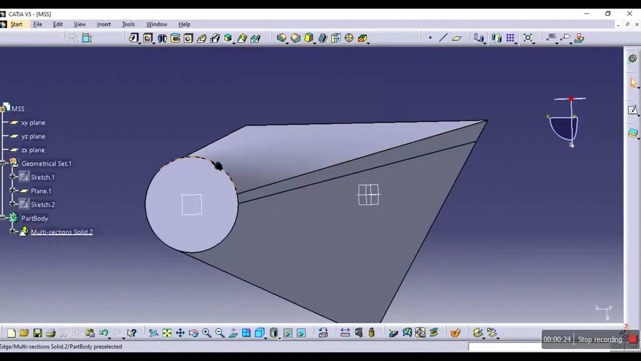
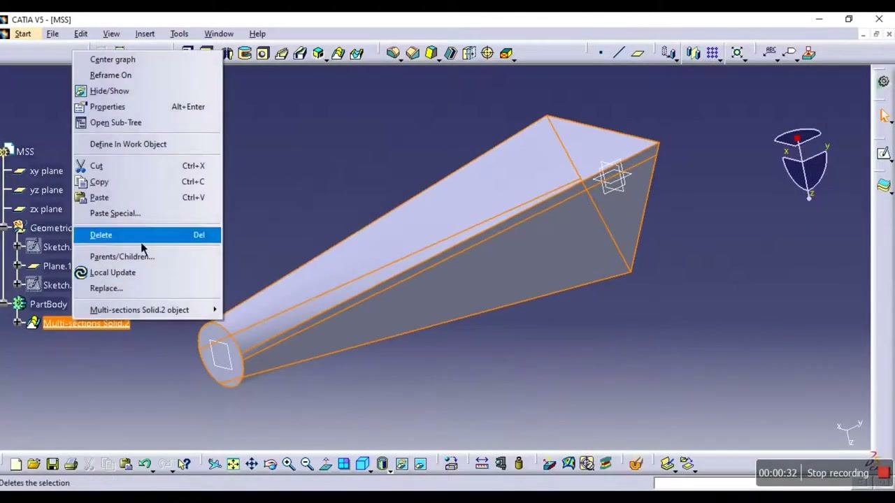
Step 10. Delete the first solid
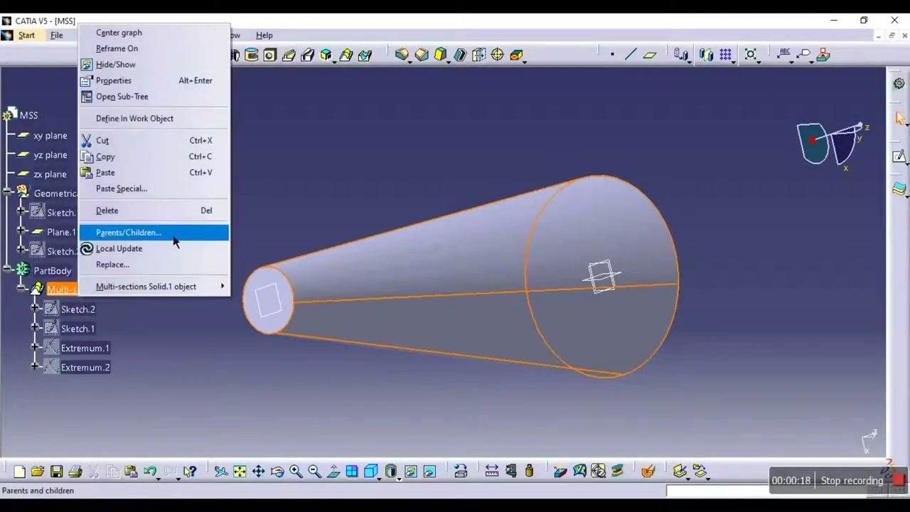
- In the tree, right-click the Multi-sections Solid.1 object.
- Select Delete.
- Confirm the deletion if prompted.
Step 11. Draw a triangle on the base plane
- Select the base plane (the ZX plane or Sketch.1).
- Enter the Sketcher workbench.
- Instead of a circle, draw an equilateral triangle inside the reference circle.
- Make sure the triangle is centered and properly dimensioned.
- Complete the sketch and exit the Sketcher workbench.
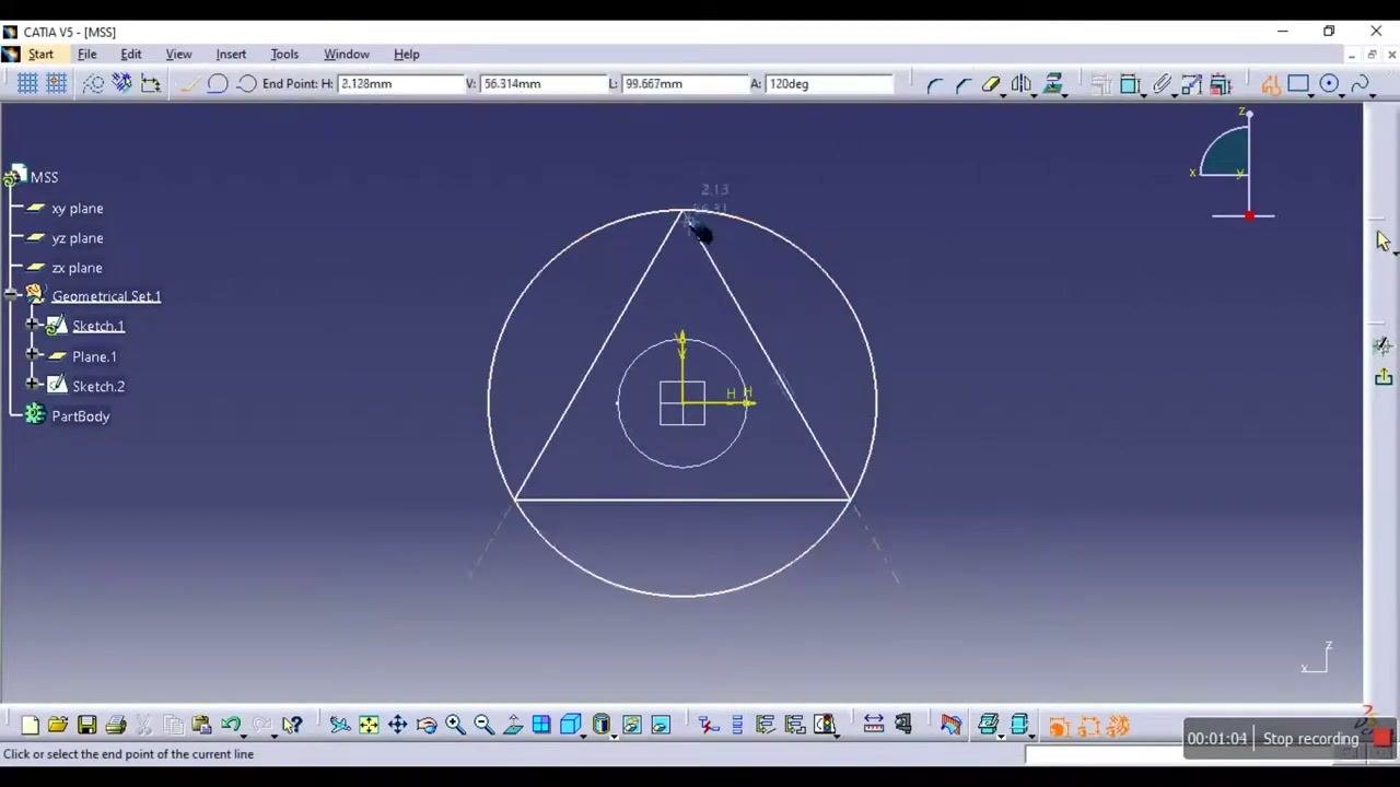
You now have sketches for a multi-section solid with different section profiles: a triangle and a circle.
Step 12. Select the circle and triangle as sections
- Select the Multi-Section Solid command from the toolbar.
- In the dialog, set Sketch.2 (circle) as the first section.
- Set Sketch.1 (triangle) as the second section.
Step 13. Preview the solid and read the error
Click Preview in the Multi-Sections Solid Definition dialog. An error appears, indicating that the current coupling mode cannot be applied.
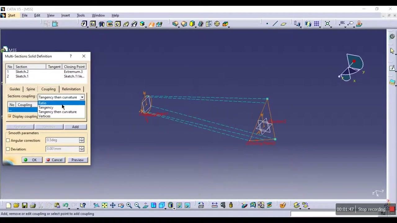
Step 14. Change the coupling mode to Ratio
- Go to the Coupling tab in the Multi-Sections Solid Definition dialog.
- Change the Sections coupling option from "Tangency then curvature" to Ratio.
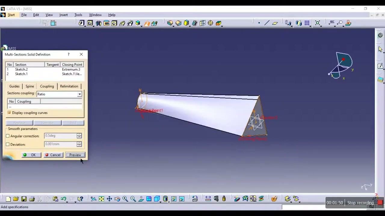
- Click Preview again to generate the solid.
The solid forms and transitions smoothly between the triangle and the circle. The transition creates multiple surfaces and edges, typically four to five, rather than just three.
Step 15. Inspect the resulting geometry
Rotate and zoom in on the solid to examine the surfaces and edges. The triangle's three edges result in several surfaces connecting to the circle.
Get three surfaces with the Vertices coupling mode
Step 16. Understand why the Vertices coupling mode is needed
To get three connecting surfaces, use the Vertices coupling mode. This mode matches each triangle vertex to a specific point on the circle.
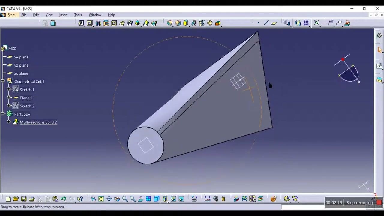
The triangle has three sides, three edges, and three vertices. The circle has no vertices or edges, which is the root of the coupling issue.
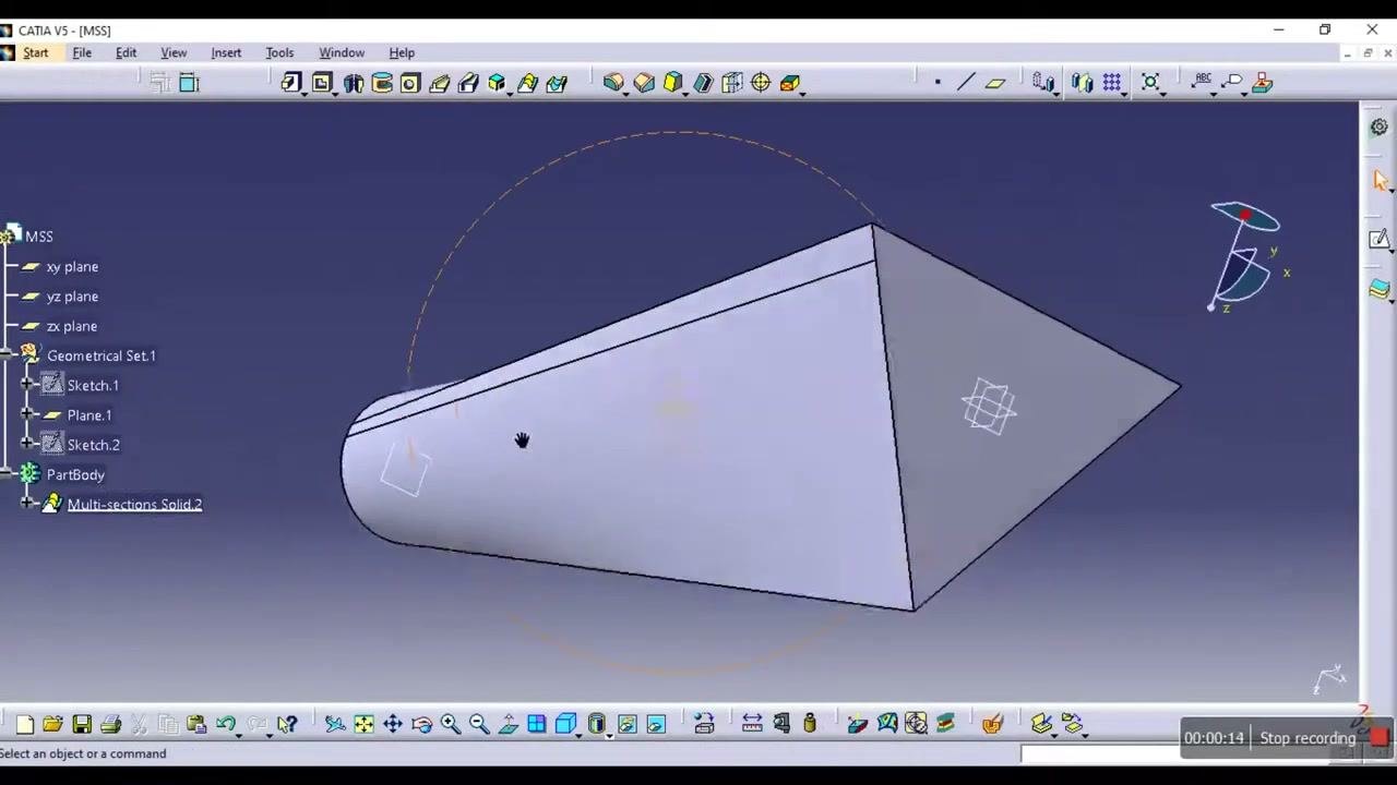
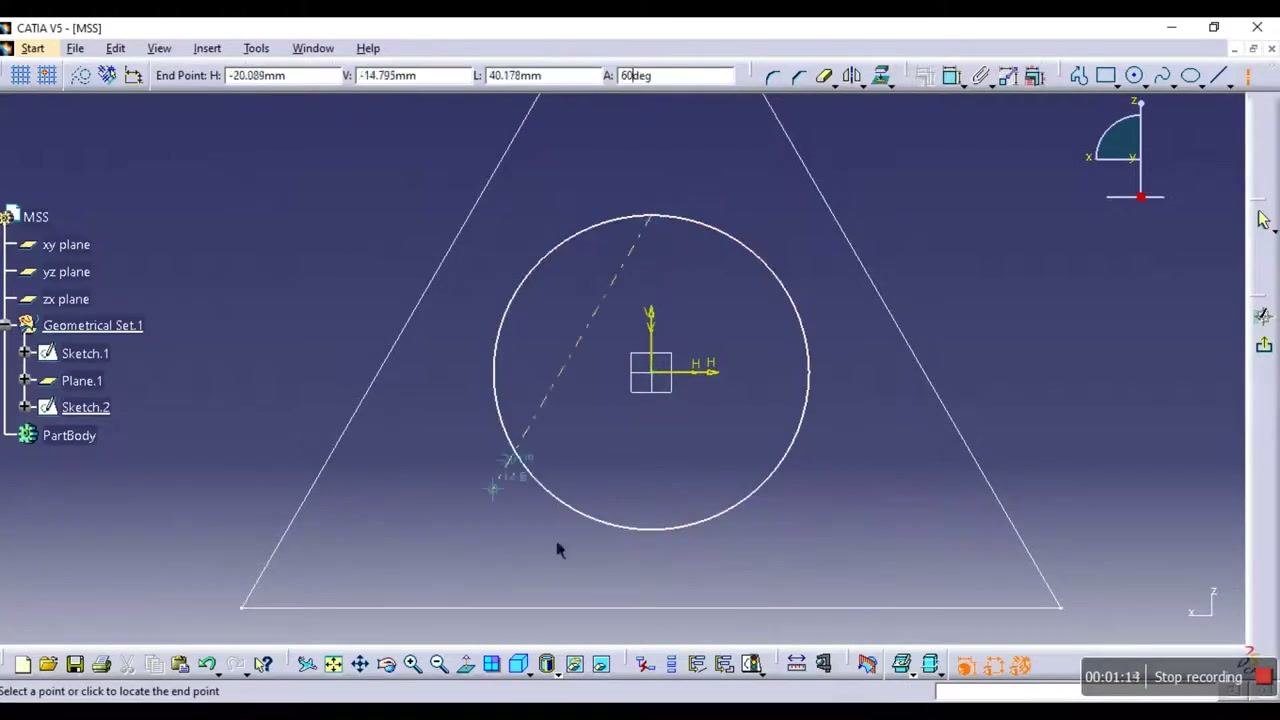
Step 17. Divide the circle into three equal parts
- Create or select a sketch that contains a circle.
- Draw lines from the center of the circle to its circumference, spaced 120° apart, to divide the circle into three equal sectors.
- Make sure the lines are placed accurately for an equal division.
Step 18. Trim the circle
- Go to the Trim command in the Sketcher workbench.
- Select "Trim and Keep" to remove unnecessary segments while keeping the required geometry.
- Trim the circle and lines so that only the three equal sectors remain.
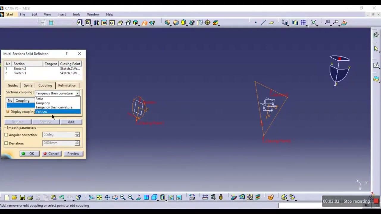
Step 19. Set the Vertices coupling in the Multi-Sections Solid Definition dialog
Make sure you have at least two sketches on parallel planes. One holds the divided circle (for example, Sketch.2). The other holds a different profile (for example, the triangle in Sketch.1).
- Activate the Multi-Sections Solid tool.
- In the dialog, select the first section (for example, Sketch.2) and the second section (for example, Sketch.1).
- Go to the Coupling tab.
- Set Sections coupling to "Vertices" for precise vertex-to-vertex mapping.
- Click Preview to visualize the resulting solid.
Step 20. Confirm and create the solid
If the preview is correct, click OK to generate the multi-section solid. The solid transitions smoothly from the circle to the triangle.
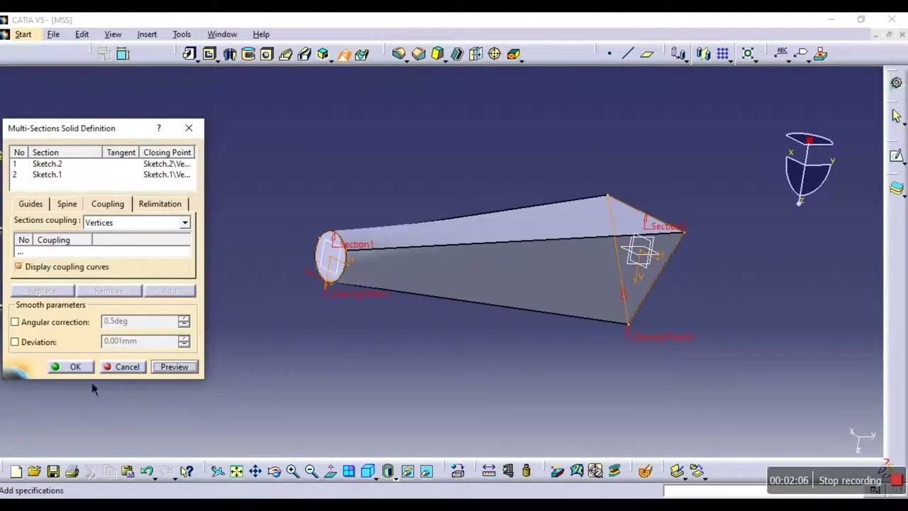
Step 21. Experiment with different end profiles
To create a solid that transitions from a circle to a hexagon, repeat the same steps with a hexagon sketch at one end. Divide the circle into six equal parts (60° apart) for accurate vertex mapping.
The resulting solid transitions smoothly between the two profiles, for example circle to triangle or circle to hexagon. The process is the same each time. Only the number of divisions and the end profile change.
Note:
- Make sure the number of divisions in the circle matches the number of vertices in the end profile for proper coupling.
- Use the "Vertices" coupling mode for precise mapping between corresponding points on each profile.
Follow a curved path with a spine
You can also use multi-section solid in CATIA V5 to build a solid that follows a curved path (a spine) rather than a straight line.
Step 22. Start the spine curve
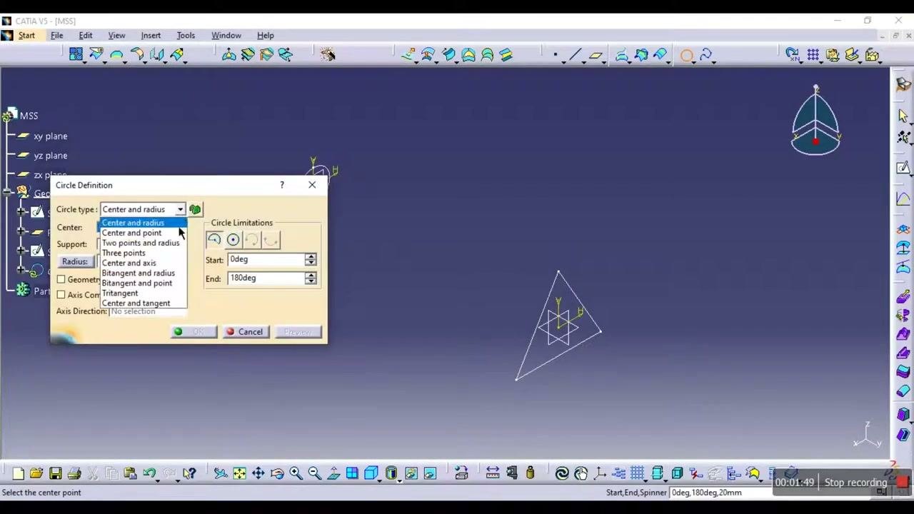
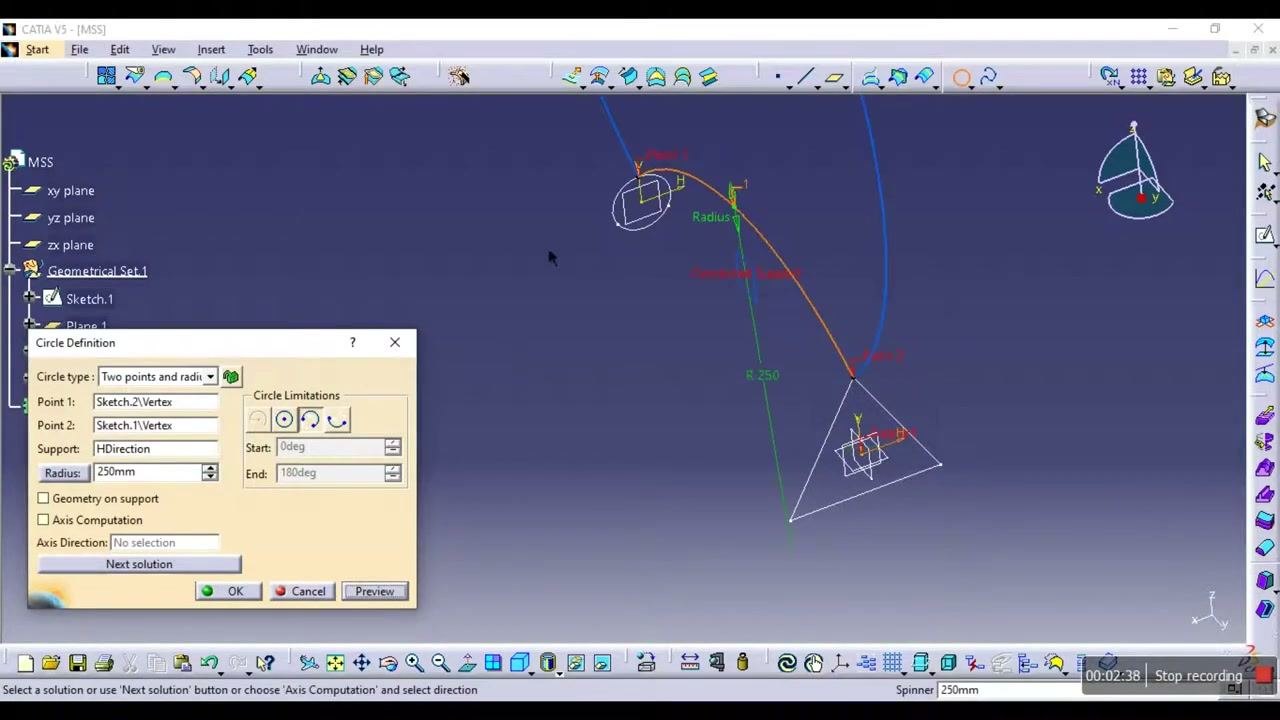
- Open the Circle Definition dialog to create a guiding arc (the spine) between the two section profiles.
- Select "Center and radius" as the circle type. The dialog offers several circle creation methods.
Step 23. Select the points for the spine
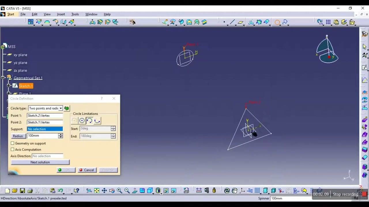
- Change the circle type to "Two points and radius".
- For Point 1, select a vertex on the circle sketch (
Sketch.2\Vertex). - For Point 2, select a corresponding vertex on the triangle sketch (
Sketch.1\Vertex).
The dialog now shows both points selected, ready to define the arc.
Step 24. Set the support and adjust the radius
- Set Support to
HDirection(horizontal direction). - Enter a radius value, for example 100mm.
- If an error says the radius is too short, increase the radius value.
The dialog and workspace display the selected points and support, with error messages if the radius is insufficient.
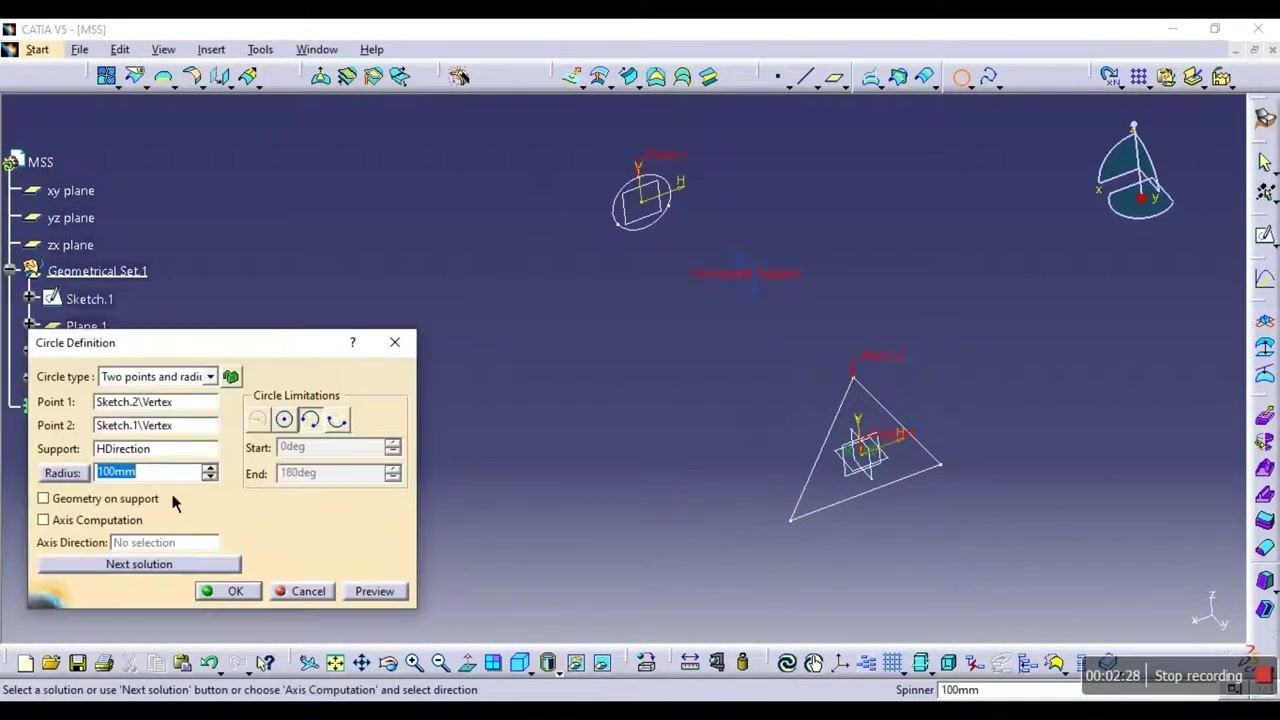
Increase the radius (for example, to 250mm) until the arc is created between the two points. The arc (spine) appears in the workspace, connecting the circle and triangle sketches. The dialog shows the updated radius, and the arc is labeled with its radius and endpoints.
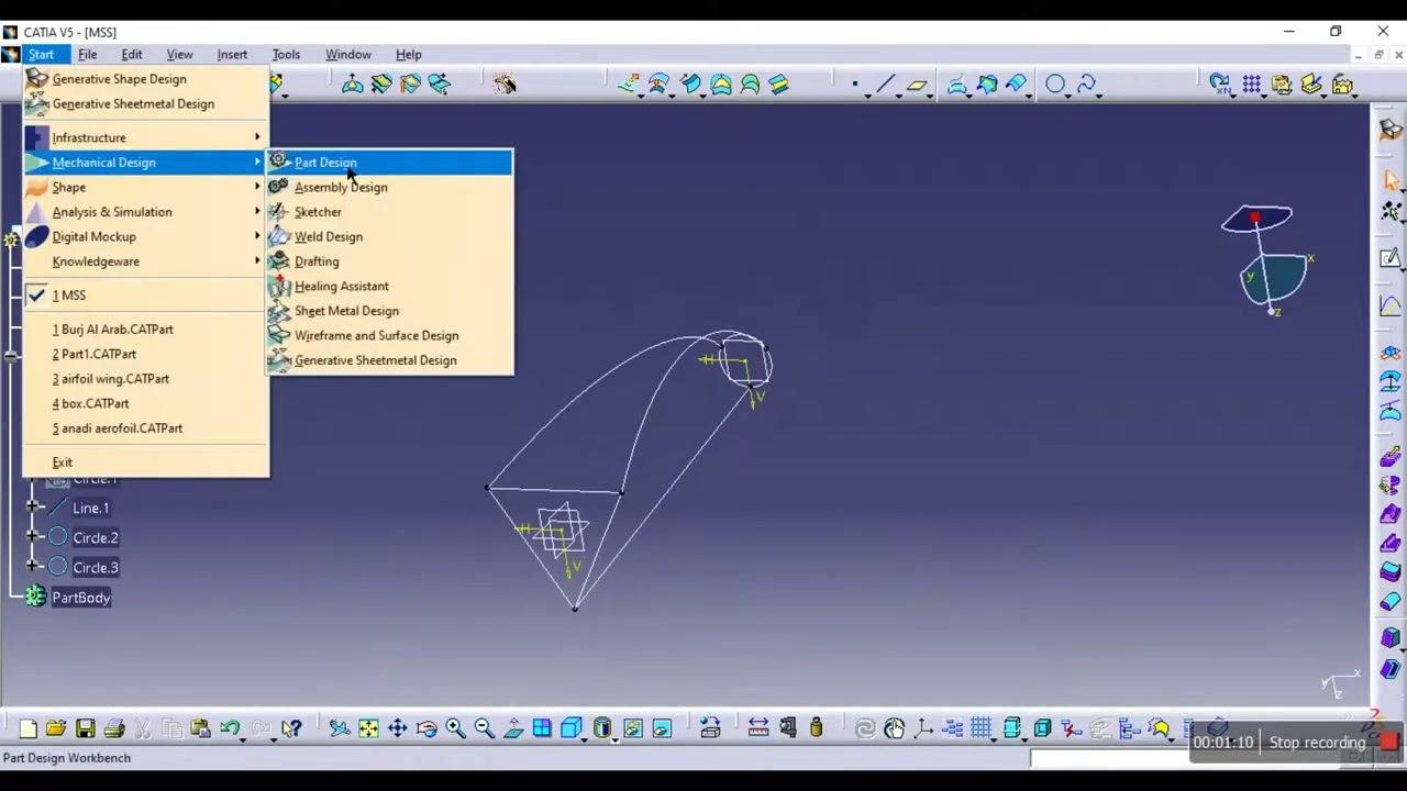
Step 25. Switch back to the Part Design workbench
Go to Start > Mechanical Design > Part Design. The workspace shows the two sketches and the new arc (spine), ready for multi-section solid creation.
Note:
- The spine (arc) guides the transition between the two section profiles, so the solid is curved rather than straight.
- Make sure the arc is properly defined and connects the correct vertices for accurate geometry.
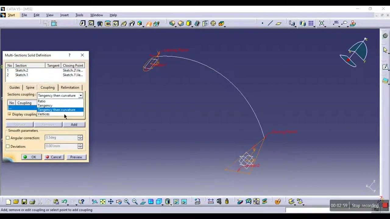
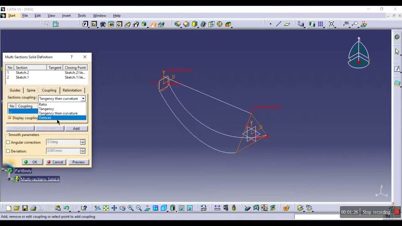
Step 26. Divide the section profiles and set the coupling
Make sure both section profiles (the circle and the triangle) are divided into three equal parts. This division is necessary for accurate coupling between the profiles.
- Open the Multi-Sections Solid Definition dialog and select the Coupling tab.
- In the Sections coupling dropdown, select "Tangency then curvature" to control how the sections are blended.
The workspace shows the two section sketches at each end of the arc, with labeled points indicating the divisions.
Step 27. Select the spine curve
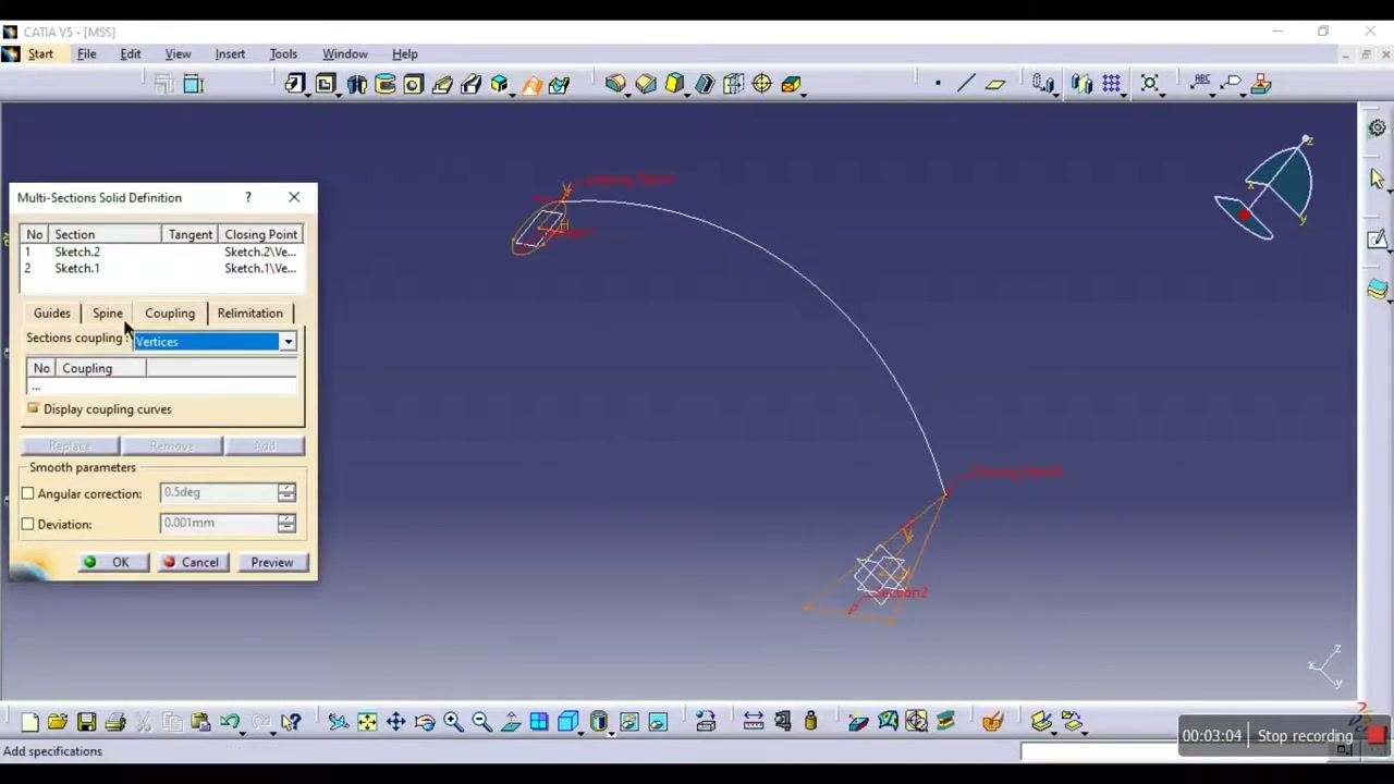
- Switch to the Spine tab in the Multi-Sections Solid Definition dialog.
- In the Spine field, select the arc (for example,
Circle.1) as the guiding curve. - Click Preview to visualize the resulting solid.
Step 28. Preview and confirm the curved solid
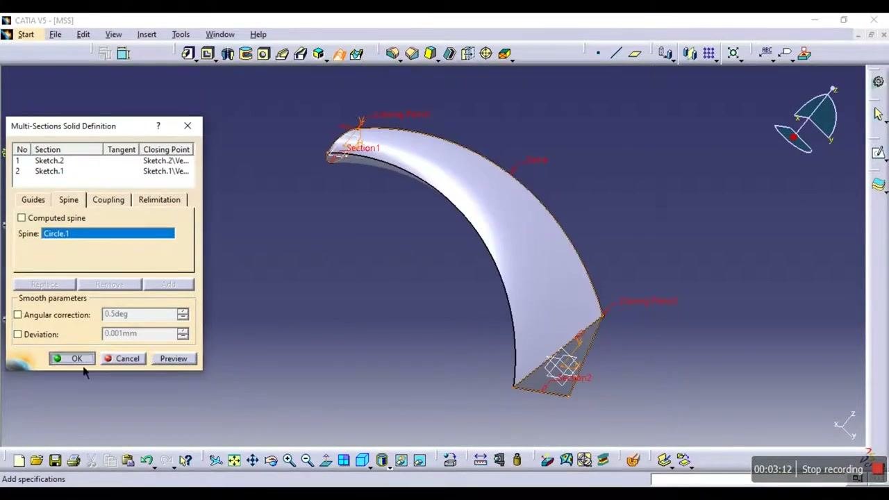
After you click Preview, the solid appears in the workspace. It transitions from a triangle at one end to a circle at the other, following the curved spine. The dialog stays open and shows the computed spine and smooth parameter settings.
Click OK to finalize the curved multi-section solid.
Add guide curves and lines
Step 29. Delete the existing multi-section solid
- In the part tree, right-click
Multi-sections Solid.5. - In the context menu, select Delete to remove the current solid.
The solid is highlighted in orange, and the context menu shows the Delete option.
Step 30. Start a guide line between the section profiles
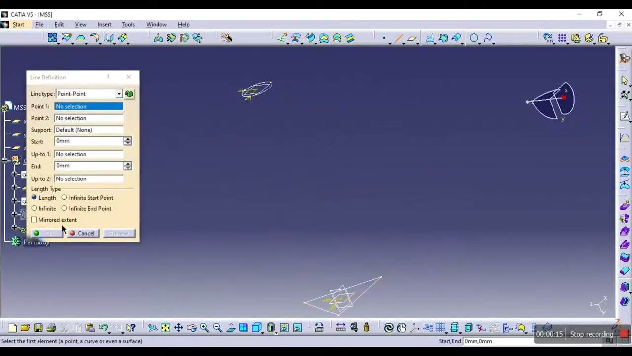
- Open the Line Definition dialog to create a new guide line.
- Set Line type to "Point-Point".
The dialog is ready for you to select the start and end points. The workspace shows the two section profiles (circle and triangle) with no solid present.
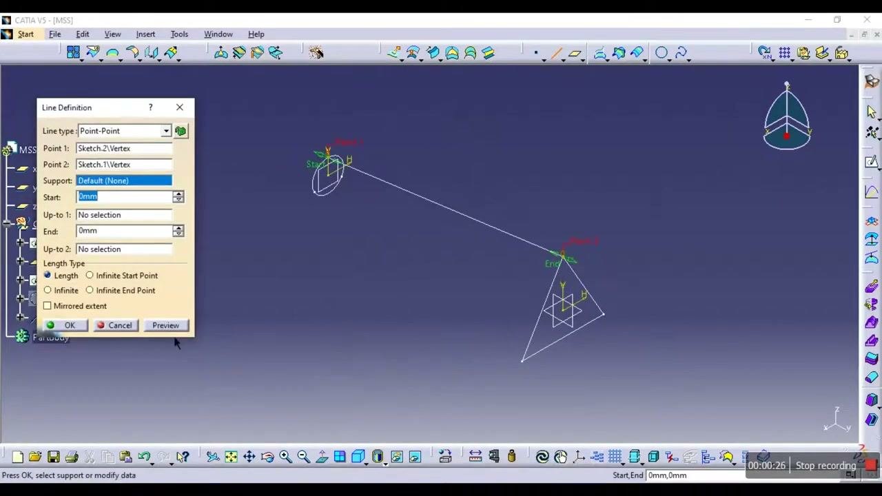
Step 31. Select the line end points
In the Line Definition dialog, select Sketch.2\Vertex as Point 1 and Sketch.1\Vertex as Point 2. A straight line connects the selected vertices of the circle and triangle sketches. The dialog confirms the selected points and the default support.
Note:
- Dividing the profiles into equal parts and using the correct coupling method ensures a smooth transition between sections.
- The spine curve determines the overall shape of the solid. Guide curves and lines give you additional control for advanced shapes.
- You can mix straight and curved sections by combining lines and curves as guides.
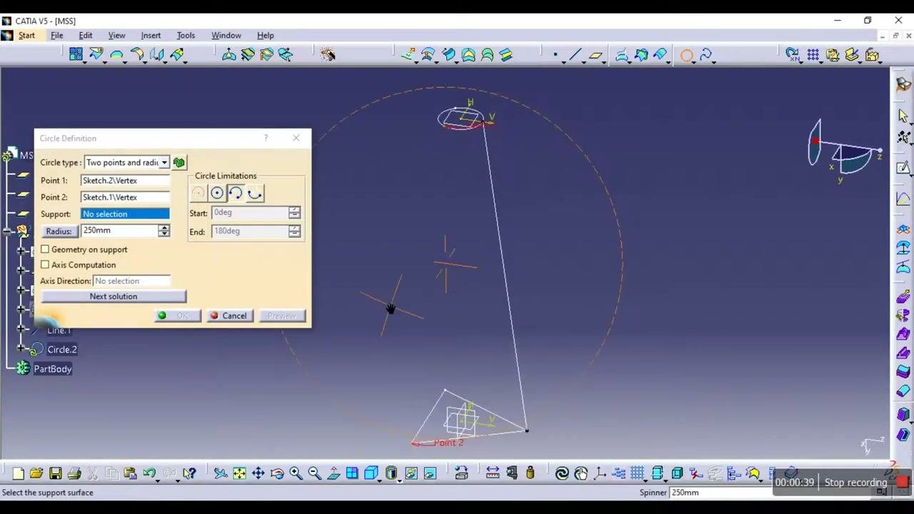
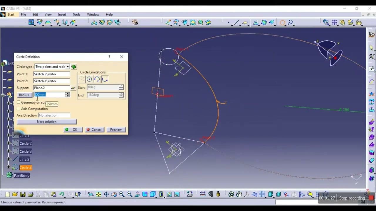
Step 32. Define a guide circle
- In CATIA V5, make sure you are in the appropriate workbench for sketching or shape design.
- Open the Circle Definition dialog.
- Set Circle type to "Two points and radius".
- For Point 1, select
Sketch.2\Vertex. For Point 2, selectSketch.1\Vertex. - Leave Support as "No selection" for now.
- Enter
250mmfor the Radius. - Under Circle Limitations, set Start to
0degand End to180deg. - Do not select "Geometry on support" or "Axis Computation" at this stage. Leave Axis Direction as "No selection".
- Click Next solution if needed to preview different circle placements.
Step 33. Assign the support plane for the circle
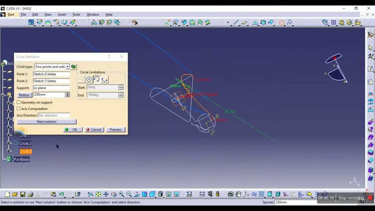
- In the Circle Definition dialog, set Support to the zx plane (or the appropriate plane for your geometry).
- Make sure Point 1 and Point 2 remain as previously set.
- Confirm the Radius is still
250mm. - Click Preview to visualize the circle in the 3D workspace.
Step 34. Return to the Part Design workbench
- Click the Start menu in the top left.
- Go to Mechanical Design > Part Design to switch workbenches.
This prepares the environment for solid modeling based on your sketches and guides.
Create the multi-section solid with guides
Step 35. Define sections, guides, and coupling
- Open the Multi-Sections Solid Definition dialog.
- On the Sections tab, select the first section (
Sketch.2) and the second section (Sketch.1). - Go to the Guides tab. Select
Line.1(the straight line) as the first guide and the relevant curve as the second guide. - On the Coupling tab, set Sections coupling to
Tangency then curvaturefor smooth transitions. - Optionally, set Angular correction to
0.5degand Deviation to0.001mmfor finer control. - Click Preview to generate a visual preview of the solid.
Step 36. Finalize the multi-section solid
- Review the preview of the generated solid in the workspace.
- If you are satisfied, click OK in the Multi-Sections Solid Definition dialog.
The new solid appears in the model tree as Multi-sections Solid.6 under PartBody.
Step 37. Inspect and rotate the solid
Use the mouse to rotate the new solid and inspect it from different angles. Confirm that the solid follows the intended guide curves and section profiles.
Step 38. Modify the guide curves for creative design
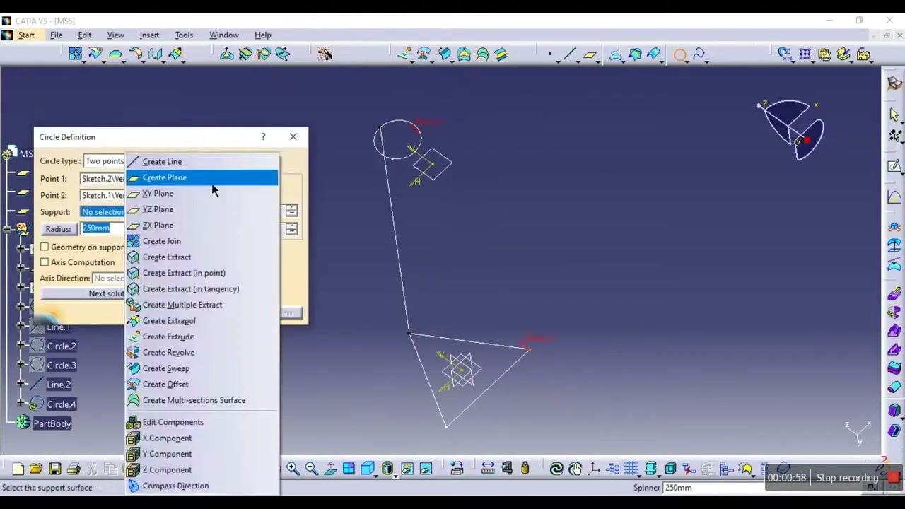
To experiment with the design, adjust the guide circle:
- Open the Circle Definition dialog again.
- Select "Create Plane" from the support options if you want to shift the circle or guide to a new location.
- Adjust the position of the circle, for example by moving it closer to the top vertex of the section.
Step 39. Preview and confirm the adjustments
- Preview the changes in the workspace after you modify the guide curve or circle position.
- Make sure the new guide placement achieves the effect you want on the solid's shape.
- Click OK to confirm and update the model.
Review the finished solid
Step 40. Compare the 3D model with the reference image
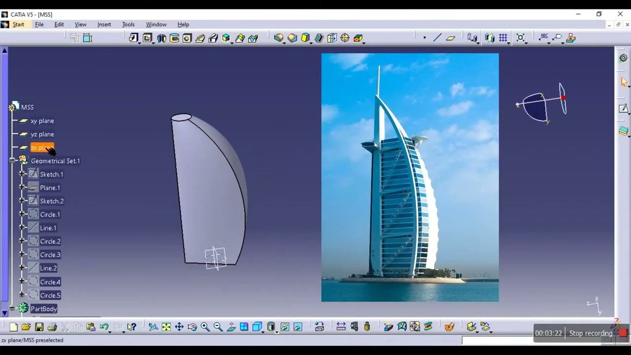
The CATIA V5 workspace shows your completed multi-section solid on the left and a reference image of a real-world structure (a sail-shaped hotel) on the right. The model tree lists the sketches, planes, circles, and lines used in the design.
Compare the shape and curvature of your 3D model with the reference image. Confirm that the solid closely matches the intended architectural form.
Step 41. End the modeling session
Save your work if you have not already done so, then conclude your CATIA V5 session.
What's next
Try other end profiles, such as a hexagon. Divide the circle into the same number of parts as the profile has vertices, and use the Vertices coupling mode. You can also change the guide circle position to explore different shapes.
Summary
In this guide, you learned how to use multi-section solid in CATIA V5. You built a solid between two circles, then switched to a triangle and a circle. You used the Ratio and Vertices coupling modes to control the surfaces. You then added a spine curve and guide curves to shape a curved solid and compared it with a reference image.
Generation details: cost, quality tiers
Docsie billed 6,500 credits ($4.55) to analyze this 13-minute video at standard quality. The rewrite, template fill and Word/PDF exports were included. The same video at each quality tier:
| Quality | Frames sampled | Credits | Approx. cost |
|---|---|---|---|
| Draft | every 16-30 s | 3,250 | $2.27 |
| Standard (this guide) | every 8-15 s | 6,500 | $4.55 |
| Detailed | every 4-7 s | 13,000 | $9.10 |
| Ultra | every 1-3 s | 26,000 | $18.20 |
Credits priced at $0.70 per 1,000; plans include a monthly allowance. Enterprise customers on on-premise or bring-your-own-model deployments run this on their own inference and pay no per-video credits.
Generated by Docsie Video-to-Docs on 2026-11-15 from a 12-minute video. Screenshots are frames from the source video and belong to their creator, MechStuff, whose original is embedded above. If you own this video and want the guide removed or credited differently, contact us and we will act within one business day.