
How to Run a Simulation in CATIA
This guide shows you how to run a simulation in CATIA V5 for a piston and cylinder assembly. You create a mechanism, fix the cylinder, add a cylindrical joint, and drive the piston along its axis. You then set the piston travel range, loop the motion, and slow the playback so you can watch the piston move.
Video: Catia V5 Simulation Tutorial For Beginners (Part 1) by Wabi Media - ዋቢ ሚዲያ (2019). All credit for the demonstration goes to the creator; watch the original on YouTube. The written guide below was generated from this video by Docsie. Creator? Request a change or removal.
This guide shows you how to run a simulation in CATIA V5 for a piston and cylinder assembly. You create a mechanism, fix the cylinder, add a cylindrical joint, and drive the piston along its axis. You then set the piston travel range, loop the motion, and slow the playback so you can watch the piston move.
Prerequisites
Before you start, make sure you have the following:
- A piston part and a cylinder part, fully assembled in CATIA V5.
- The correct product file open (for example,
Product3), with the assembled model visible in the main view area.
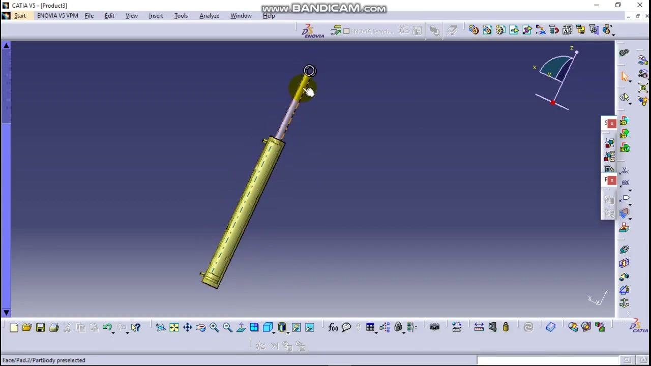
The piston and cylinder move with a cylindrical movement. The piston travels up and down inside the cylinder.
Set up the simulation environment
Step 1. Open the assembled model
Open your assembled piston and cylinder model. Confirm that the main view area displays the assembly and that you are working in the correct product file.
Step 2. Open the simulation workbench
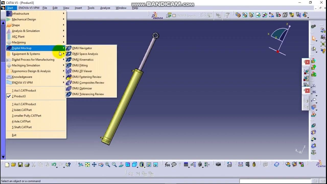
To run a simulation in CATIA, first enter the kinematics workbench:
- Click Start in the top menu.
- Hover over Digital Mockup.
- Select DMU Kinematics in the submenu.
Step 3. Zoom in on the cylinder
Use the zoom and pan tools to focus on the cylinder. This makes the part easier to select in the next step.
Step 4. Create a mechanism and fix the cylinder
Decide which part stays stationary and which part moves. Here, the cylinder is fixed and only the piston moves.
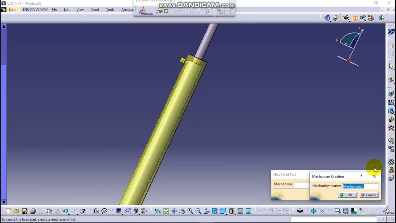
Select the cylinder, then right-click it or use the simulation toolbar to choose the option to fix the part. If CATIA prompts you, you must create a new mechanism first.
- When the "New Fixed Part" dialog appears, choose to create a new mechanism.
- In the "Mechanism Creation" dialog, enter a name. You can use any name, such as
Mechanism.1,Simulation1, orMechanism1. - Click OK.
Step 5. Verify the fixed part and the mechanism
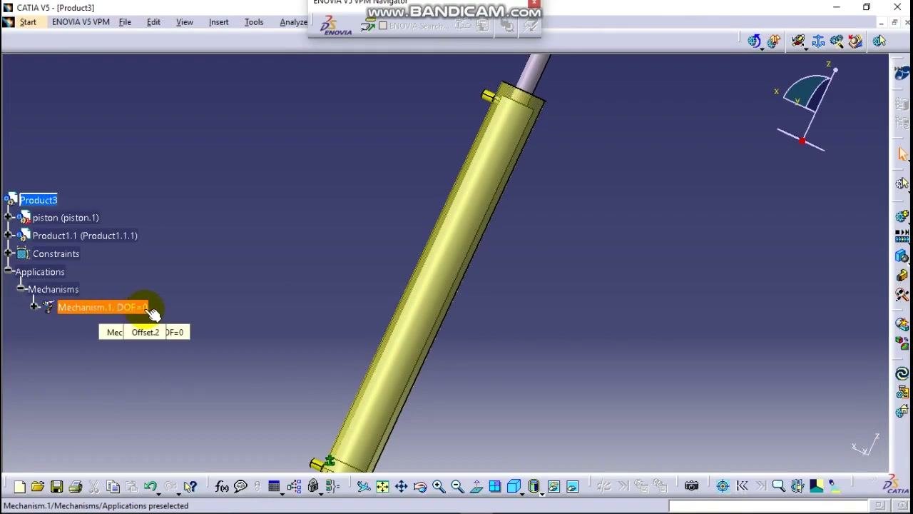
Confirm that the cylinder is the fixed part and that CATIA created the mechanism. In the model tree on the left, expand Applications > Mechanisms and check that Mechanism.1 is listed.
The mechanism shows DOF=0 (zero degrees of freedom). This means it is ready for joint definition.
Create the cylindrical joint
Step 6. Open the cylindrical joint dialog
Find the joint toolbar on the right side of the CATIA window. It offers several joint types, including Revolute, Prismatic, Cylindrical, Screw, Spherical, Planar, Rigid, and Slide Curve joints.
For a piston and cylinder mechanism, click the Cylindrical Joint icon.
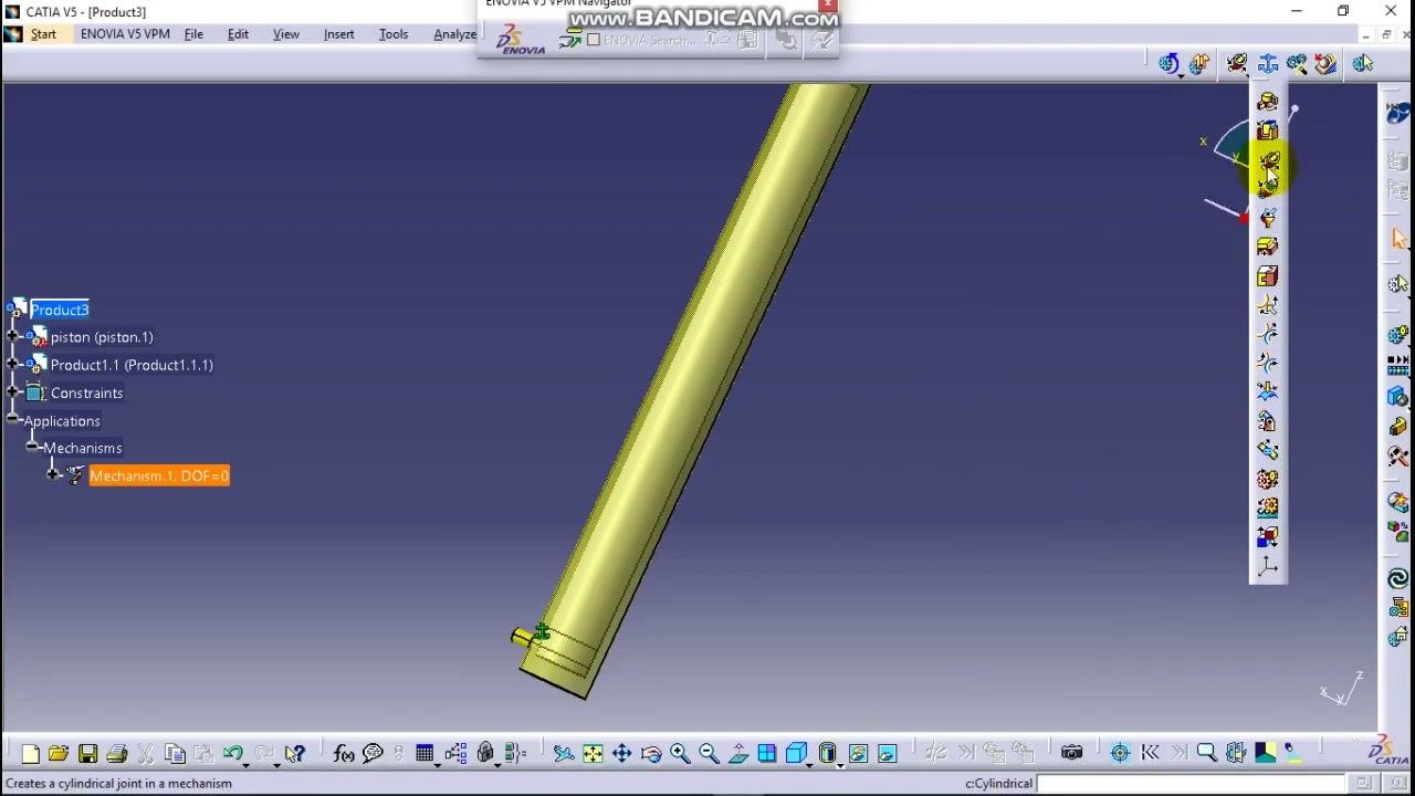
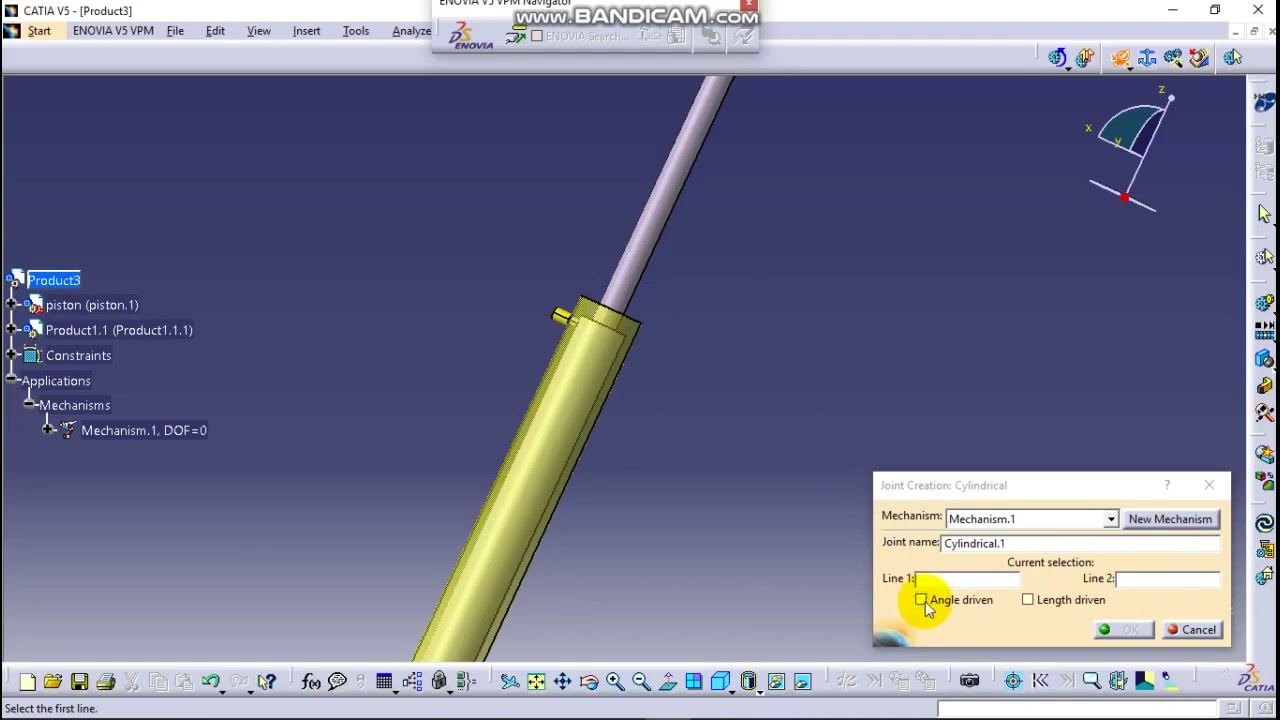
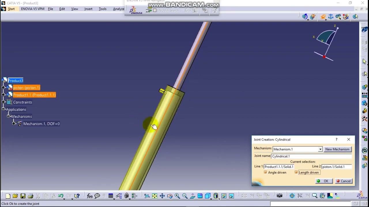
The "Joint Creation: Cylindrical" dialog appears. Check the following fields:
- Mechanism:
Mechanism.1 - Joint name:
Cylindrical.1 - Line 1: to be selected
- Line 2: to be selected
- Angle driven and Length driven: checkboxes that define the joint's driving parameters
Step 7. Select the cylinder axis as Line 1
A cylindrical joint needs two lines. Line 1 is the center axis of the cylinder, and Line 2 is the center axis of the piston. Together they define the axis along which the piston moves inside the cylinder.
You can optionally check Angle driven, Length driven, or both. Your choice depends on whether you want to control the joint by rotation, translation, or both.
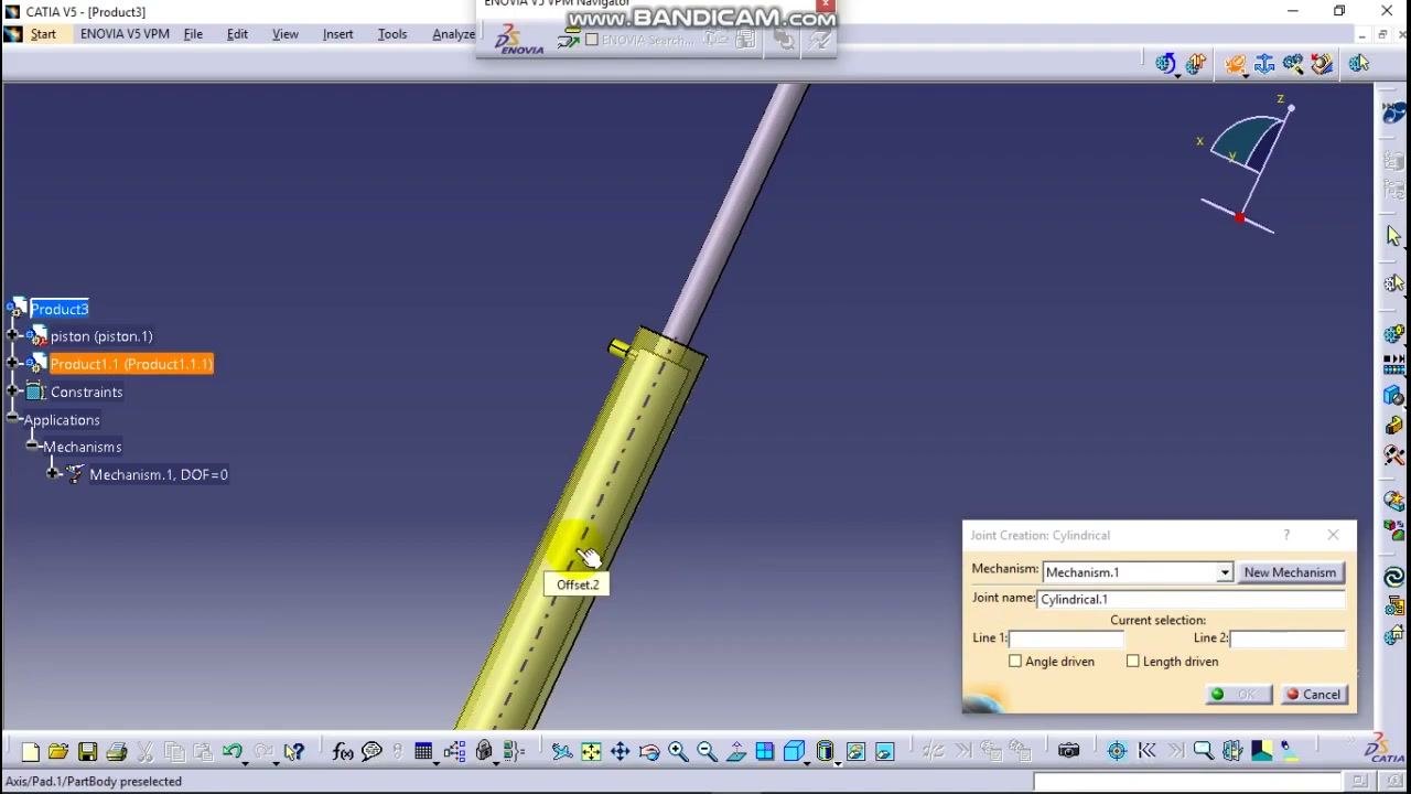
- In the dialog, click the Line 1 field.
- In the 3D view, click the center axis of the cylinder (highlighted as
Offset.2). - Confirm that the dialog shows the selection as
Product1.1/Solid.1.
Step 8. Select the piston axis as Line 2
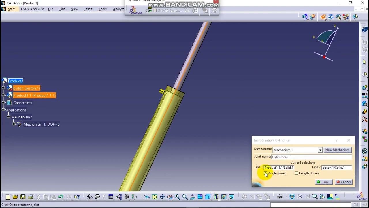
- Click the Line 2 field in the dialog.
- In the 3D view, click the center axis of the piston.
- Confirm that the dialog shows
Line 1: Product1.1/Solid.1andLine 2: piston.1/Solid.1.
Step 9. Set the joint to length driven
Check Length driven. Leave Angle driven unchecked, because the piston only moves in translation.
Review the dialog to confirm these values:
- Mechanism: Mechanism.1
- Joint name: Cylindrical.1
- Line 1: Product1.1/Solid.1
- Line 2: piston.1/Solid.1
- Length driven: checked
- Angle driven: unchecked
Step 10. Create the joint
Click OK in the dialog to create the joint. An information message appears: "The mechanism can be simulated." Click OK in the information dialog to continue.
Run the simulation and move the piston
Step 11. Open the kinematics simulation controls
Click the Simulation icon (gear and pinion symbol) on the right toolbar.
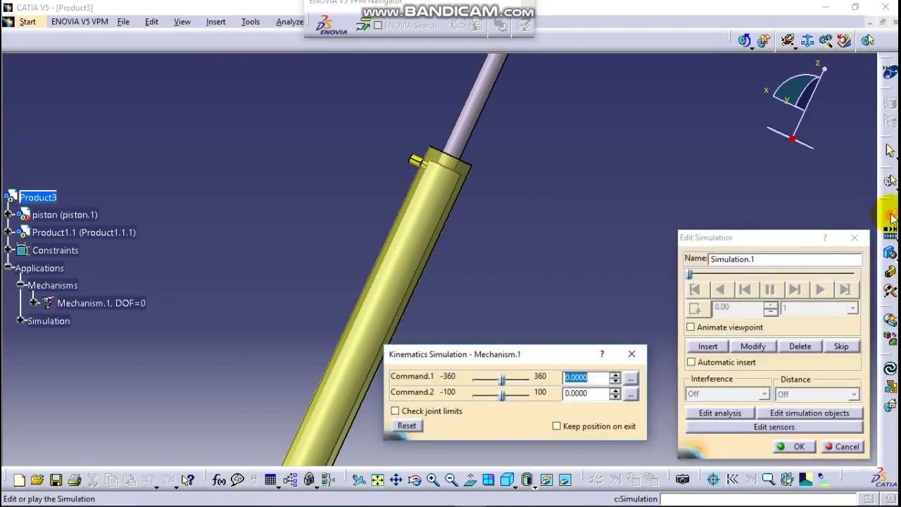
The "Kinematics Simulation - Mechanism.1" dialog appears with the "Edit Simulation" panel. It includes these controls:
- Command.1: ranges from -360 to 360. This is the degree command, which this mechanism does not use.
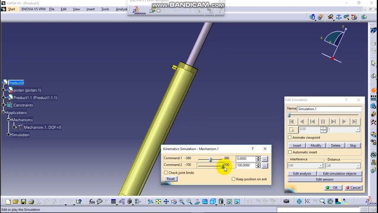
- Command.2: ranges from -100 to 100. This is the length command, and it controls the piston movement.
- Check joint limits option
- Reset button
- Edit Simulation panel with playback and animation controls
Step 12. Move the piston with Command.2
To run a simulation in CATIA with this mechanism, leave Command.1 alone, because the piston does not rotate. Use the Command.2 slider or input box to move the piston along its axis.
Adjust the value from -100 to 100 to cover the full range of piston movement. The piston moves in the 3D view as you change the value.
Configure piston travel and playback
Step 13. Edit the Command.2 slider properties
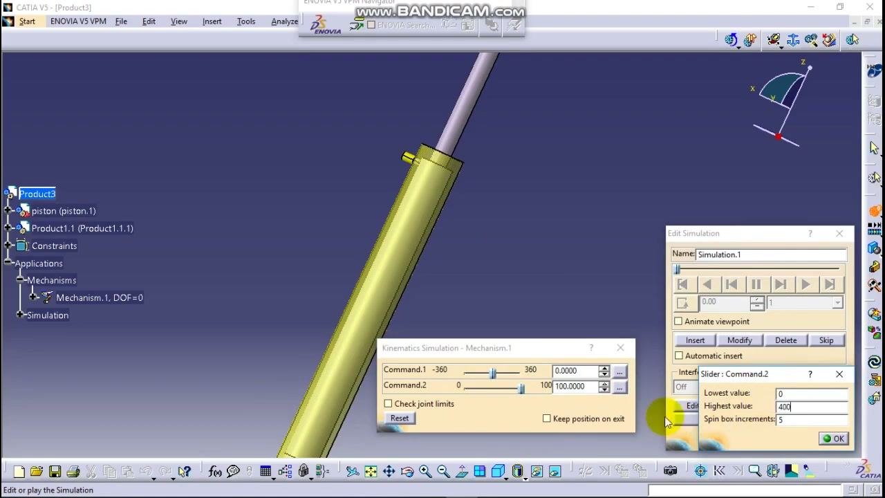
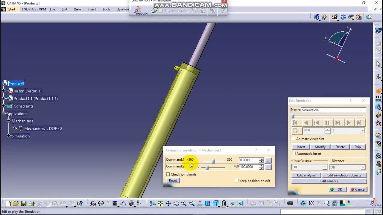
The value 100 for Command.2 represents the distance the piston can move in the simulation. To change the range, click the three-dots (ellipsis) button next to the Command.2 slider.
In the "Slider: Command.2" dialog, set these values:
Lowest value: 0Highest value: 400Spin box increments: 5
Click OK to apply the changes.
Step 14. Test the piston at the maximum value
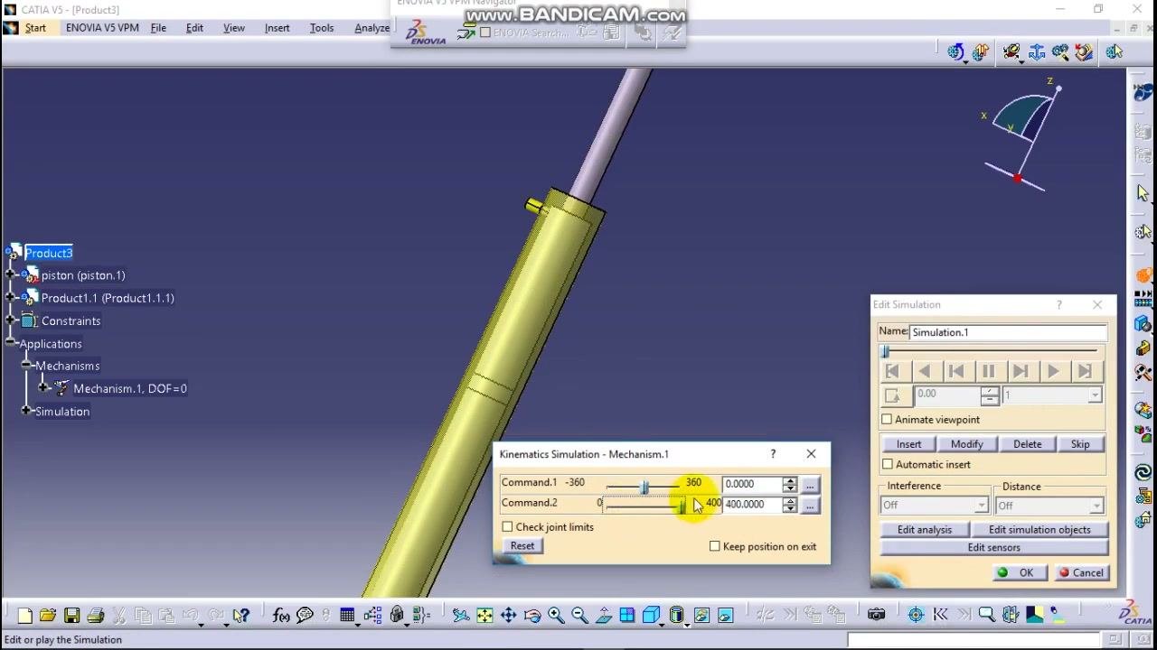
Set the Command.2 slider to 400 and watch the piston extension in the 3D view.
Step 15. Retract the piston and check for a gap
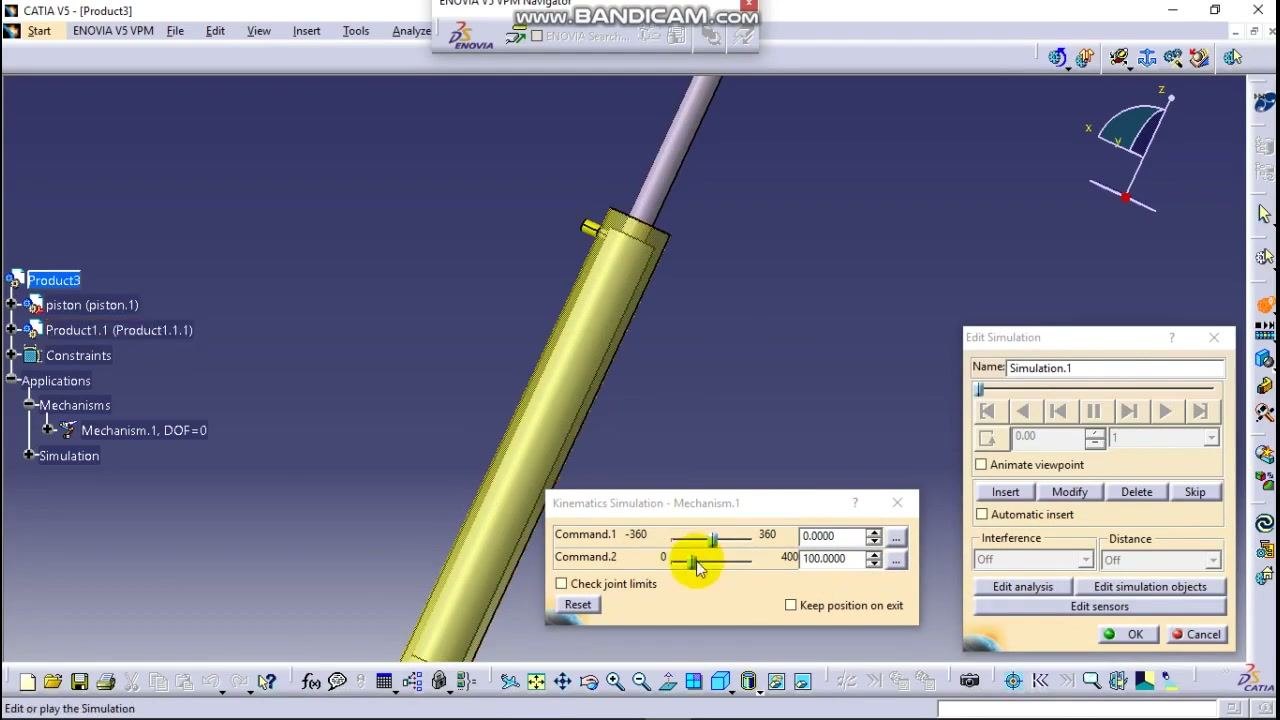
Move the Command.2 slider back to 0 to retract the piston. A gap remains between the piston head and the outlet. This means you may need to increase the maximum value.
Step 16. Increase the maximum value
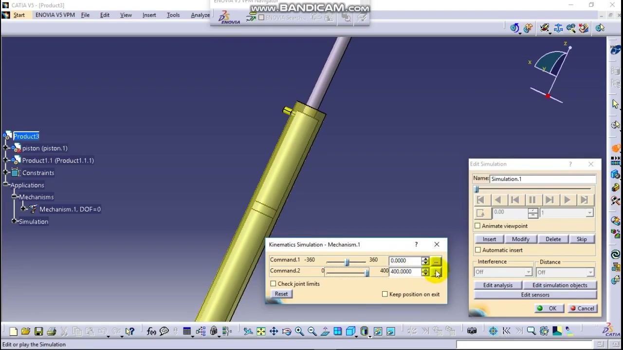
Set the highest value of Command.2 to 500 and test the slider again. If the gap persists, keep increasing the maximum in steps, for example to 600.
Step 17. Continue until the piston reaches the outlet
Keep raising the maximum value as needed. For example, set it to 600 and test the movement. When the piston head reaches the outlet or your desired position, move on to the next step.
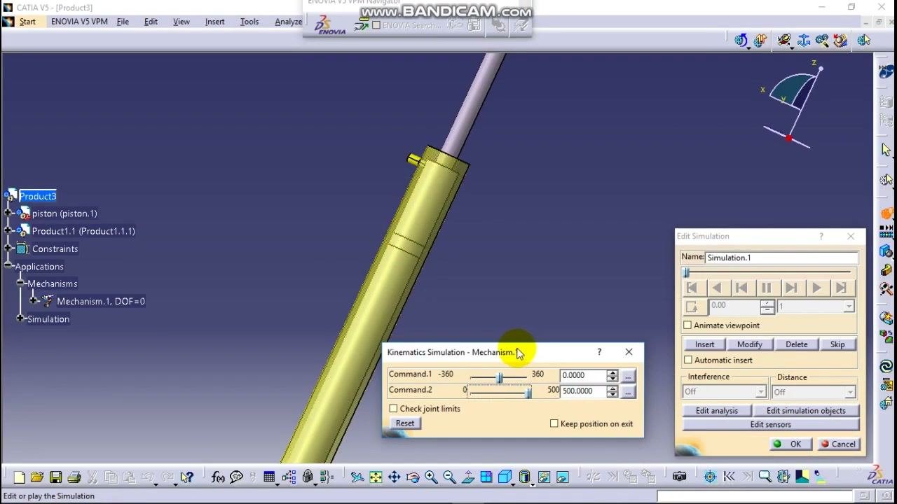
Step 18. Insert the simulation step
Click Insert in the "Edit Simulation" dialog. This records the simulation step with the updated piston travel and saves the current configuration and movement range.
Step 19. Turn on loop mode
Click the Change Loop Mode button (the icon with up and down arrows) in the "Edit Simulation" dialog. The simulation now plays back and forth automatically.
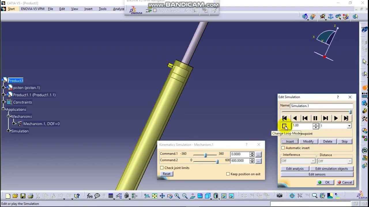
Step 20. Switch to one-direction playback (optional)
To play the simulation in only one direction, click the loop mode button again until the arrows point in the same direction.
Adjust the simulation speed
Step 21. Slow the playback to make the motion visible
When you run a simulation in CATIA with the default speed, the piston can move too fast to see. At this point, the 3D view shows the piston extended from its cylinder. The dialogs show the following:
- "Kinematics Simulation - Mechanism.1": Command.1 ranges from -360 to 360 with a value of 0.0000.
- Command.2 ranges from 0 to 600 with a value of 600.0000.
- Check joint limits is enabled.
- "Edit Simulation": the playback controls are visible and the speed is 1.00.
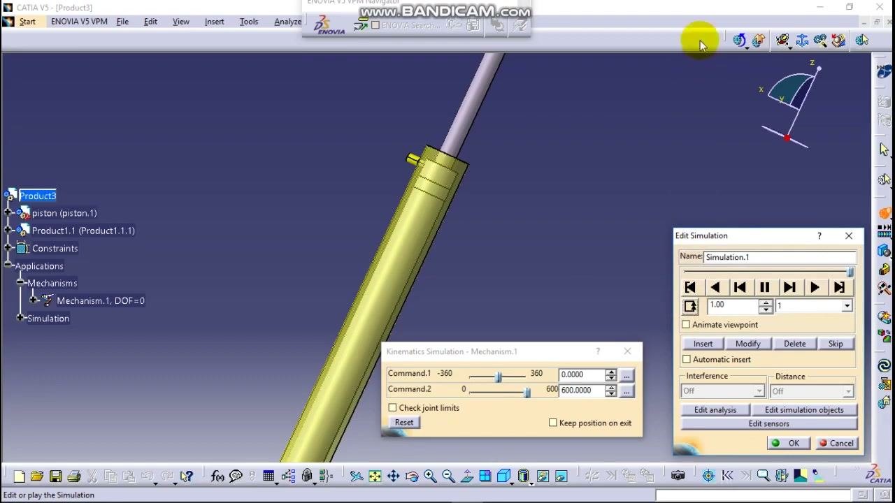
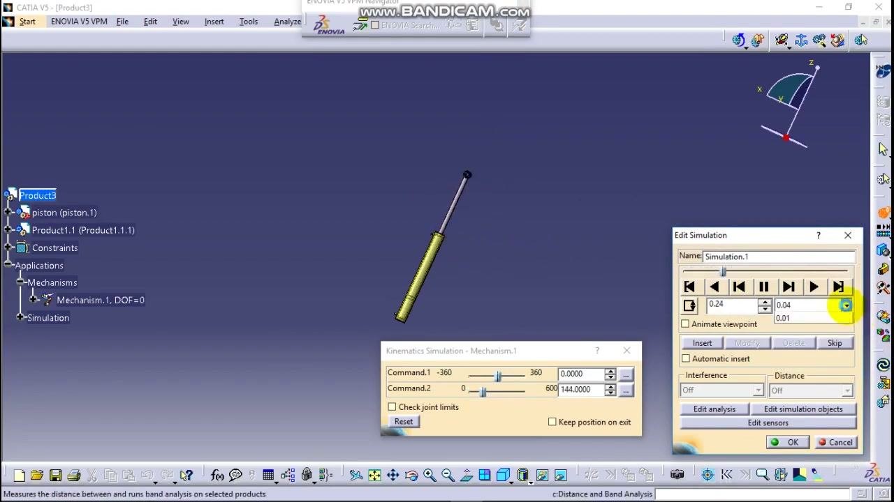
A speed of 1.00 can make the piston movement nearly invisible. In the "Edit Simulation" dialog, open the speed dropdown to the right of the playback controls. It offers 1, 0.2, 0.1, 0.04, 0.02, and 0.01. Select a lower value, such as 0.1 or 0.04.
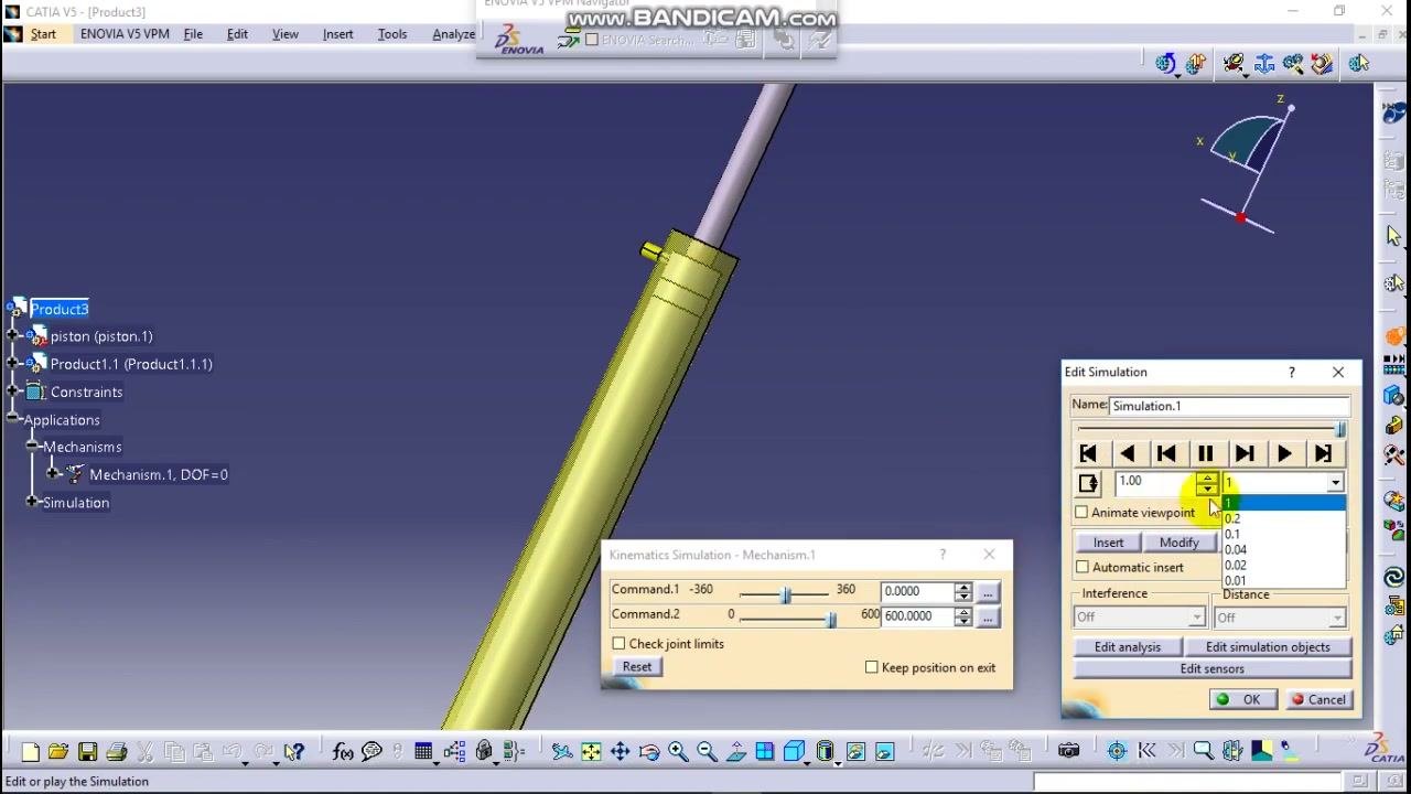
Step 22. Play the simulation at the reduced speed
Click the play button in the "Edit Simulation" dialog. The piston now moves slowly and visibly between its retracted and extended positions.
The Command.2 value in the "Kinematics Simulation" dialog updates as the simulation progresses, for example 300.0000 and 144.0000.
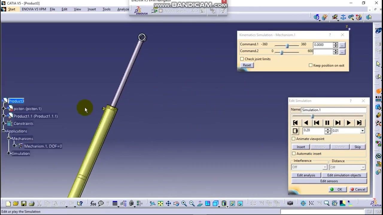
Step 23. Zoom and pan the 3D view
Use the mouse or navigation tools to zoom and reposition the 3D view. You can watch the simulation from different angles to confirm that the motion is what you expect.
Summary
You now know how to run a simulation in CATIA V5 for a piston and cylinder mechanism:
- You created a mechanism and fixed the cylinder.
- You defined a length-driven cylindrical joint using the cylinder and piston axes.
- You moved the piston with Command.2 and extended its travel range until it reached the outlet.
- You turned on loop mode and lowered the playback speed so the up-and-down motion is easy to see.
What's next
Continue with further analysis of the mechanism or with exporting your simulation results.
Generation details: cost, quality tiers
Docsie billed 5,000 credits ($3.50) to analyze this 10-minute video at standard quality. The rewrite, template fill and Word/PDF exports were included. The same video at each quality tier:
| Quality | Frames sampled | Credits | Approx. cost |
|---|---|---|---|
| Draft | every 16-30 s | 2,500 | $1.75 |
| Standard (this guide) | every 8-15 s | 5,000 | $3.50 |
| Detailed | every 4-7 s | 10,000 | $7.00 |
| Ultra | every 1-3 s | 20,000 | $14.00 |
Credits priced at $0.70 per 1,000; plans include a monthly allowance. Enterprise customers on on-premise or bring-your-own-model deployments run this on their own inference and pay no per-video credits.
Generated by Docsie Video-to-Docs on 2026-11-15 from a 9-minute video. Screenshots are frames from the source video and belong to their creator, Wabi Media - ዋቢ ሚዲያ, whose original is embedded above. If you own this video and want the guide removed or credited differently, contact us and we will act within one business day.