
How to Rotate Part in CATIA
This guide shows you how to rotate a part in CATIA V5 with the compass. You first create an axis in Generative Shape Design, snap the compass onto it, and then rotate the part by an exact increment. Using a defined axis keeps the rotation accurate, which matters most in large assemblies or when you work to millimeter precision.
Video: Catia V5 Tutorial-93 Compass Rotate Part by Jlaiel khaled (2013). All credit for the demonstration goes to the creator; watch the original on YouTube. The written guide below was generated from this video by Docsie. Creator? Request a change or removal.
This guide shows you how to rotate a part in CATIA V5 with the compass. You first create an axis in Generative Shape Design, snap the compass onto it, and then rotate the part by an exact increment. Using a defined axis keeps the rotation accurate, which matters most in large assemblies or when you work to millimeter precision.
Prerequisites
- CATIA V5 installed and running.
- Tutorial part number 87 from the DVD.
- Access to the Generative Shape Design workbench.
Steps
Open the tutorial part
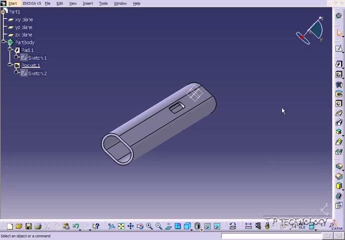
Open CATIA V5 and load tutorial part number 87 from the DVD. The model tree appears on the left and the 3D part appears in the center of the workspace. The compass is in the upper right corner of the workspace.
Decide where the rotation axis should be
Before you rotate the part in CATIA, decide where you want to rotate it, for example along a specific line or axis. Then plan to create an axis at that location. This way you are 100% certain about the rotation axis.
Placing the compass on different faces or locations gives different rotation results. This is true for the W axis or for a spot near the center of a circle. Even if you think you are at the center, you may not be exactly there, because the compass can still move slightly.
To get a precise result, create geometry such as a line or axis within your circles or curves. Always use a straight line or axis for compass rotation.
Switch to Generative Shape Design
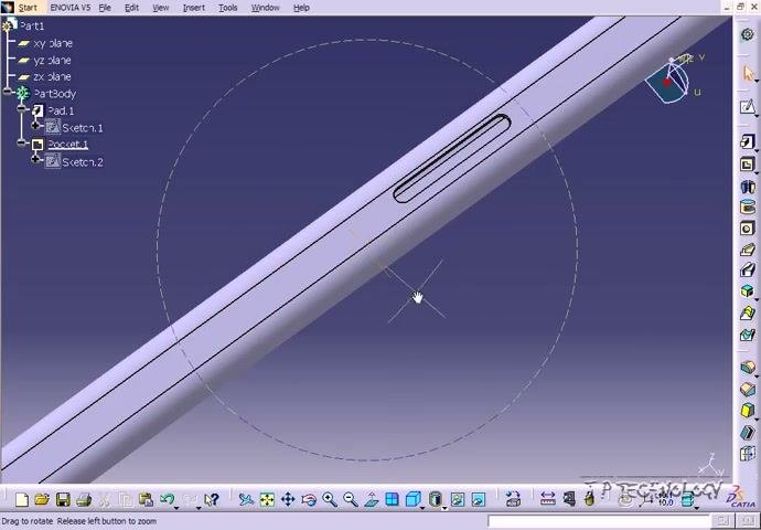
- In the top menu, click Start.
- Go to Shape.
- Select Generative Shape Design from the dropdown menu.
This module lets you create reference geometry, such as lines and axes, for precise operations.
Create a point at the center of each end curve
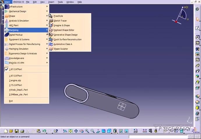
You create the axis so that it runs through the center of the part. Start with a point at the center of each end curve.
- Click the Point tool in the toolbar.
- In the Point Definition dialog, change Point type to Circle/Sphere center.
- Click the first end curve of the part. CATIA automatically places a point at the center of the selected curve.
- Click OK to create the first point.
Repeat the process for the opposite end. Click the Point tool again, select the other end curve, make sure Circle/Sphere center is selected, and click OK to create the second point.
Create the axis line between the two points
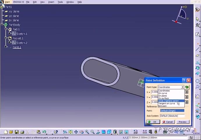
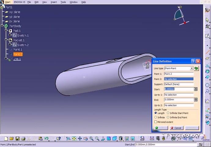
- Click the Line tool in the toolbar.
- In the Line Definition dialog, set Line type to Point-Point.
- For Point 1, select the first point you created.
- For Point 2, select the second point.
- Click OK to create the line (axis) between the two points.
Verify the axis
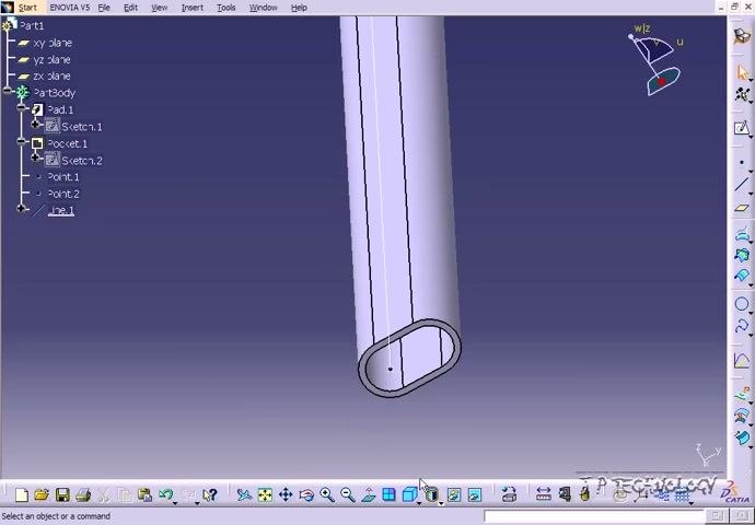
The new line runs through the part from end to end. Switch to a front view to check the axis alignment more easily.
If you place the compass at various locations without using the axis line, you may get different rotation results.
Snap the compass onto the axis
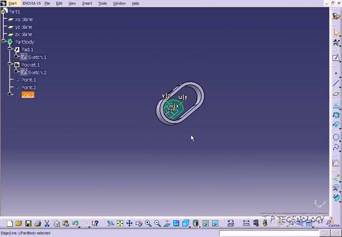
Drag the compass and snap it directly onto the axis line you created. The compass is now constrained to move only along the axis line. Because it cannot move off the line, the rotation about your chosen axis is 100% accurate.
For small parts, minor inaccuracies may not be noticeable. For large assemblies or millimeter-level precision, defining the axis is critical. Always create and use an explicit axis for compass rotation to avoid cumulative errors in complex designs.
Highlight all features you want to rotate
Select the entire part and all its features, either in the specification tree or directly in the 3D view. Make sure all relevant elements are highlighted before you continue. The compass should still be snapped to the axis line.
Open the compass rotation parameters
To start rotating the part in CATIA, use either of these options:
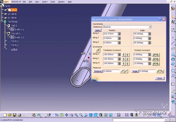
- Click the plane you want to rotate around.
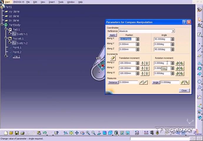
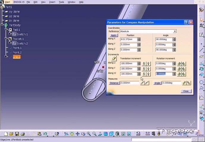
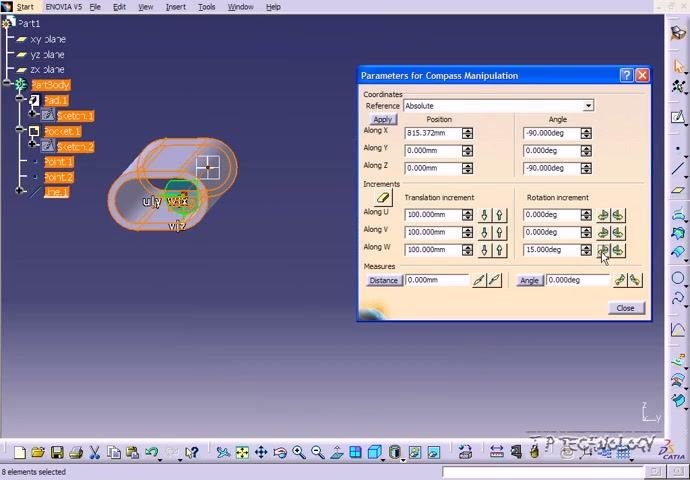
- Double-click the compass to open the rotation parameters dialog.
Set the rotation increment
- In the Parameters for Compass Manipulation dialog, find the Rotation increment section.
- In the field next to the W axis, enter
15.000deg.
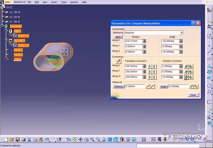
The part will now rotate exactly 15 degrees around the defined axis.
Select the part body and all features
Click PartBody in the specification tree to select the main part. Make sure all features, such as pads, sketches, and points, are also selected so the whole part rotates together.
Rotate the part
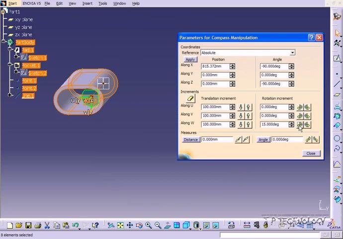
Click the rotation button (circular arrow) in the Parameters for Compass Manipulation dialog to apply the rotation. The part rotates exactly 15 degrees around the axis you defined.
Verify the rotation
Confirm that the part rotated as intended and that all features keep their correct positions relative to the axis. The axis ensures 100% accuracy and prevents misalignment or errors.
Creating the axis is what makes the rotation accurate.
If you don't use an axis, you may get mixed results.
Summary
- Always create and use a defined axis for any rotation operation in CATIA V5.
- Use the Point tool with Circle/Sphere center to place points at the centers of the end curves. Then use the Line tool to connect them.
- Snap the compass to the axis so it cannot move off the line.
- Use the Parameters for Compass Manipulation dialog to control rotation increments precisely.
- Select all relevant features so the entire part rotates as a unit.
- Double-check the result, especially in complex assemblies.
What's next
Keep using the compass along the defined axis for every rotation operation. This maintains accuracy throughout your design process and keeps your parts positioned exactly as required.
Generation details: cost, quality tiers
Docsie billed 2,500 credits ($1.75) to analyze this 5-minute video at standard quality. The rewrite, template fill and Word/PDF exports were included. The same video at each quality tier:
| Quality | Frames sampled | Credits | Approx. cost |
|---|---|---|---|
| Draft | every 16-30 s | 1,250 | $0.88 |
| Standard (this guide) | every 8-15 s | 2,500 | $1.75 |
| Detailed | every 4-7 s | 5,000 | $3.50 |
| Ultra | every 1-3 s | 10,000 | $7.00 |
Credits priced at $0.70 per 1,000; plans include a monthly allowance. Enterprise customers on on-premise or bring-your-own-model deployments run this on their own inference and pay no per-video credits.
Generated by Docsie Video-to-Docs on 2026-11-15 from a 4-minute video. Screenshots are frames from the source video and belong to their creator, Jlaiel khaled, whose original is embedded above. If you own this video and want the guide removed or credited differently, contact us and we will act within one business day.