
How to Make a Pyramid in CATIA
If you want to learn how to make a pyramid in CATIA V5, you first need the core Part Design workflow: a constrained base sketch, a point in 3D space, a plane, and a solid feature. This guide walks you through that workflow. You sketch a rectangle, dimension it, add a point and a plane, extrude a pad, and cut a pocket. You then repeat the pocket in a circular pattern and measure the finished part.
Video: Create a Pyramid in CATIA v5 Part Design by workbenchstuff (2020). All credit for the demonstration goes to the creator; watch the original on YouTube. The written guide below was generated from this video by Docsie. Creator? Request a change or removal.
If you want to learn how to make a pyramid in CATIA V5, you first need the core Part Design workflow: a constrained base sketch, a point in 3D space, a plane, and a solid feature. This guide walks you through that workflow. You sketch a rectangle, dimension it, add a point and a plane, extrude a pad, and cut a pocket. You then repeat the pocket in a circular pattern and measure the finished part.
The example in this guide produces a rectangular pad with a patterned pocket. It does not produce a pyramid.
Prerequisites
- CATIA V5 installed and ready to open.
Steps
Start a new part to begin your pyramid in CATIA
- Open CATIA V5. The application window shows a starry background and the main menu bar at the top.
- Click the Start menu in the upper left corner.
- Hover over Mechanical Design in the dropdown menu.
- Select Part Design from the extended menu.
Open the sketch environment
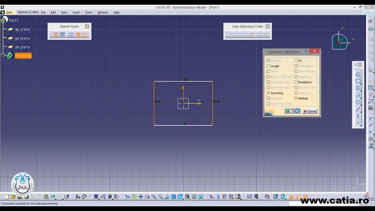
The Part Design workbench opens. The tree on the left shows Part1 with the default planes (xy plane, yz plane, zx plane) and PartBody.
The main area shows a grid with axes and a highlighted rectangle that marks the sketching area. The Sketch tools and User Selection Filter toolbars are visible. A Constraint Definition dialog also appears, where you set geometric constraints for the sketch.
Select the constraints you need, such as Length, Symmetry, or Vertical.
Constrain the base rectangle
- Select the rectangle in the sketch area.
- In the Constraint Definition dialog, check the constraints you want, such as Length, Symmetry, or Horizontal.
- Click the green OK button to apply them.
The sketch lines turn green, which shows the rectangle is fully constrained.
Define the sketch dimensions
- In the new Constraint Definition dialog that prompts for a value, enter
83for the selected constraint, such as the length or width. - Click OK to confirm.
The rectangle now shows dimension labels, such as 83 and 60.
Create a point in 3D space
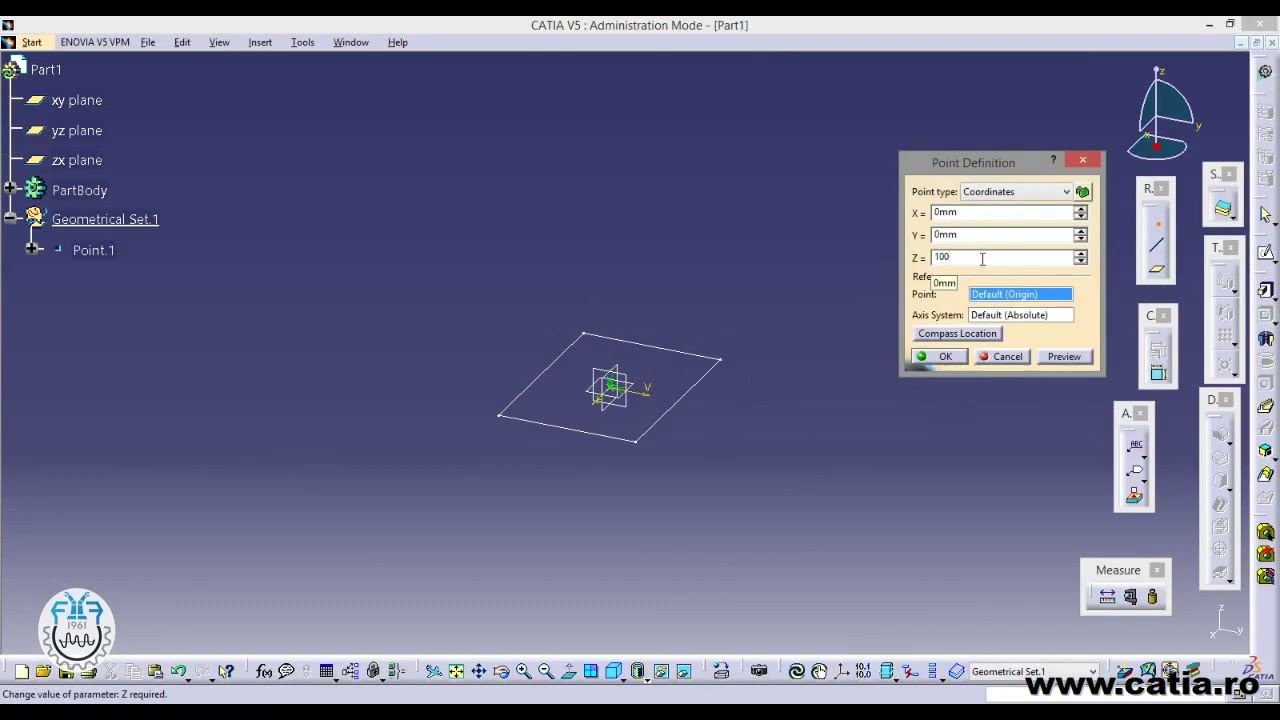
- Switch to a 3D view. The tree now includes
Geometrical Set.1withPoint.1. - In the Point Definition dialog, set Point type to Coordinates.
- Enter
X = 0mm,Y = 0mm, andZ = 100mm. - Make sure Point is set to Default (Origin) and Axis System is set to Default (Absolute).
- Click OK to create the point.
Define a plane through points
- In the Plane Definition dialog, set Plane type to Through three points.
- For Point 1, select
Point.1. - For Point 2, select
Sketch.1\Vertex. - Leave Point 3 as No selection for now.
The new plane appears in the 3D view and is listed as Plane.1 under Geometrical Set.1 in the tree.
Create the 3D pad
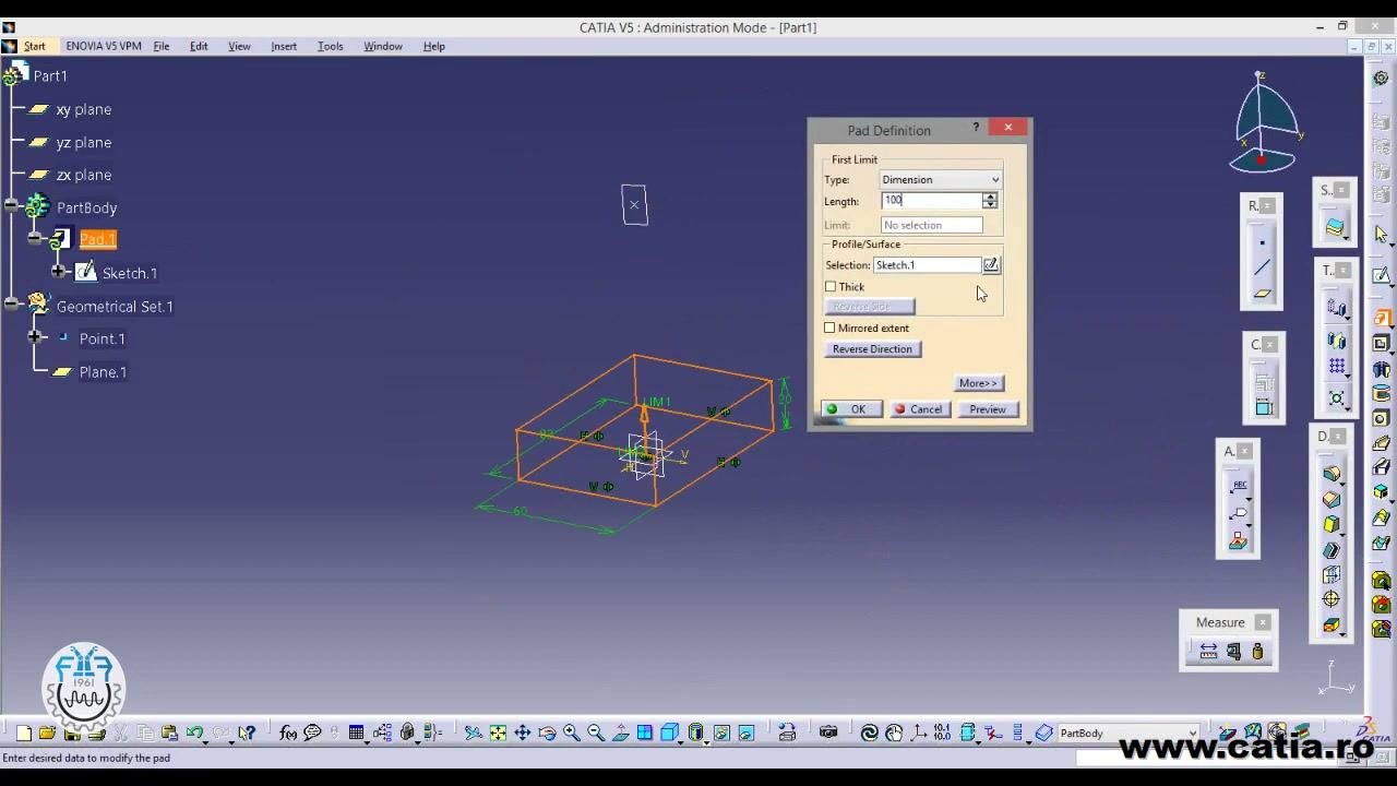
- In the Pad Definition dialog, set Type to Dimension.
- Enter
Length = 100. - Make sure Selection is set to
Sketch.1. - Optionally, check or uncheck Thick, Mirrored extent, or Reverse Direction.
- Click OK to create the pad.
The tree now shows Pad.1 under PartBody.
Inspect the pad
The workspace now shows a solid rectangular box. You can rotate it with the mouse to view it from different angles.
The tree shows the structure Part1 > PartBody > Pad.1 > Sketch.1 and Geometrical Set.1 > Point.1, Plane.1.
Confirm the pocket feature
The Pocket Definition dialog shows these settings:
- Type: Dimension
- Depth: 100mm
- Selection: Sketch.2
- Options: Thick, Mirrored extent, and Reverse Direction are unchecked.
The 3D view shows orange outlines as a preview of the pocket, and Pocket.1 is highlighted under PartBody in the tree. Click the green OK button to create the pocket.
Start a circular pattern of the pocket
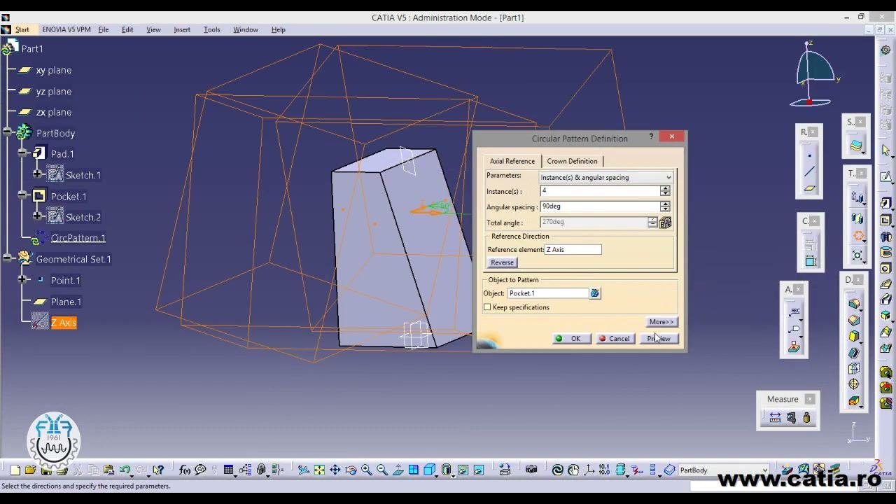
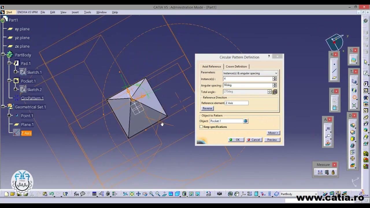
The Circular Pattern Definition dialog lets you duplicate the pocket in a circular array. Set these parameters:
- Instance(s): 4
- Angular spacing: 90 degrees
- Total angle: 270 degrees
- Object to Pattern: Pocket.1
- Keep specifications: unchecked
For Reference Direction, open the dropdown to choose a reference element. The options include X Axis, Y Axis, Z Axis, Create Line, Create Plane, and Create Compass Direction. The tree now shows CircPattern.1 under PartBody.
Set the reference axis
- With the dialog still open, set Reference element to Z Axis.
- Check the orange outlines in the 3D view, which show the previewed pattern positions around the solid. The tree lists
Z AxisunderGeometrical Set.1. - Click Preview to visualize the pattern before you confirm it.
Review the circular pattern preview
Rotate the 3D view to a top-down perspective. The dialog still shows 4 instances, 90 degree angular spacing, a 270 degree total angle, Z Axis as the reference element, and Pocket.1 as the object.
The orange outlines show the four patterned pockets distributed around the Z axis. Check that the pattern is correct before you finalize it.
Measure the volume and surface area
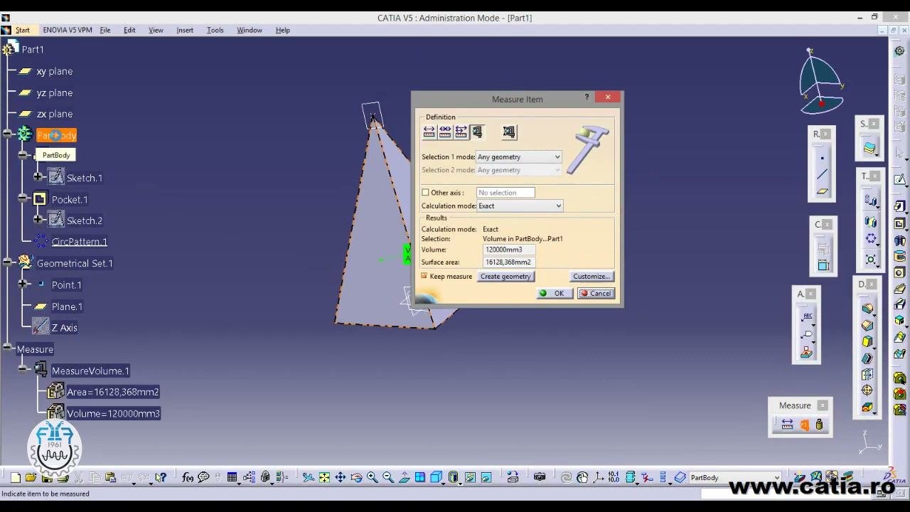
The Measure Item dialog shows the measurement results for the part:
- Calculation mode: Exact
- Selection: Volume in PartBody...Part1
- Volume: 1200000 mm³
- Surface area: 16128.368 mm²
The tree now includes a Measure section with MeasureVolume.1, which lists the area and volume. Click OK to close the dialog.
View the final measurement results
The 3D view shows the part with a green label that reads Volume = 1200000 mm³ and Area = 16128.368 mm².
The tree confirms the part structure, including the pad, pocket, circular pattern, and measurement results. The workspace shows only the part and the measurement label.
Summary
You created a 3D part in CATIA V5. You sketched and constrained a rectangular base, added a point and a plane, extruded a pad, and created a pocket. You then patterned the pocket around the Z axis and measured the part's volume and surface area. These are the same building blocks you use when you learn how to make a pyramid in CATIA.
What's next
- Rotate the finished part and compare it with the tree structure.
- Change the circular pattern parameters and use Preview to see how the result changes.
Generation details: cost, quality tiers
Docsie billed 1,500 credits ($1.05) to analyze this 3-minute video at standard quality. The rewrite, template fill and Word/PDF exports were included. The same video at each quality tier:
| Quality | Frames sampled | Credits | Approx. cost |
|---|---|---|---|
| Draft | every 16-30 s | 750 | $0.52 |
| Standard (this guide) | every 8-15 s | 1,500 | $1.05 |
| Detailed | every 4-7 s | 3,000 | $2.10 |
| Ultra | every 1-3 s | 6,000 | $4.20 |
Credits priced at $0.70 per 1,000; plans include a monthly allowance. Enterprise customers on on-premise or bring-your-own-model deployments run this on their own inference and pay no per-video credits.
Generated by Docsie Video-to-Docs on 2026-11-15 from a 2-minute video. Screenshots are frames from the source video and belong to their creator, workbenchstuff, whose original is embedded above. If you own this video and want the guide removed or credited differently, contact us and we will act within one business day.