
How to Make a Cone in CATIA
This guide shows you how to make a cone in CATIA V5. You sketch a right triangle profile in Part Design, apply constraints, and revolve the profile 360 degrees around an axis with the Shaft tool. You then inspect the finished 3D cone.
Video: CATIA V5 Tutorial #5 | Cone | Beginner by 2D3D Technologies (2021). All credit for the demonstration goes to the creator; watch the original on YouTube. The written guide below was generated from this video by Docsie. Creator? Request a change or removal.
This guide shows you how to make a cone in CATIA V5. You sketch a right triangle profile in Part Design, apply constraints, and revolve the profile 360 degrees around an axis with the Shaft tool. You then inspect the finished 3D cone.
Prerequisites
- CATIA V5 installed and ready to open.
Steps
Start a new part in Part Design
To begin making a cone in CATIA, open the Part Design workbench:
- Open CATIA V5.
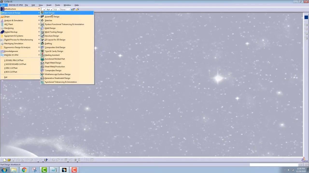
- In the top menu bar, select Start > Mechanical Design > Part Design.
- In the dropdown menu under Mechanical Design, click Part Design to begin a new part.
Before you click, the workspace background shows a starry pattern, and the left panel lists the available files and modules.
After you click, the workspace changes to a dark blue background. In the tree on the left, under the part name (for example, "CONE"), you see three default planes (xy plane, yz plane, and zx plane) and a PartBody. A coordinate system appears in the center of the workspace. No geometry is present yet.
Start the sketch and draw the axis line
Select a plane to start a new sketch. The xy plane is a common choice. The workspace stays dark blue, and the sketch tools become available.
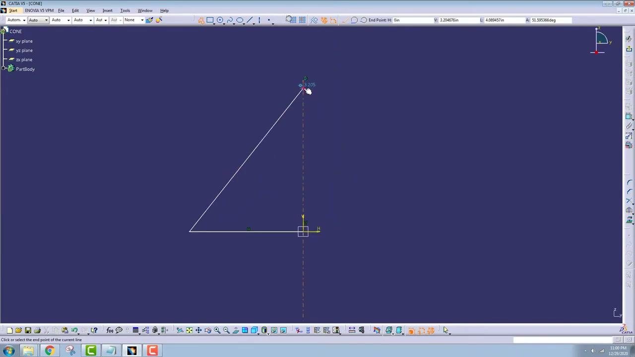
Draw a vertical construction line from the origin upwards. Use the cursor to define the endpoint. Coordinate values appear near the cursor as you draw.
Draw the cone profile
Continue sketching by drawing two lines to form a right triangle. This triangle is the cone profile that you revolve. The triangle has:
- One vertical side, which is the axis of revolution.
- One horizontal base.
- One slanted side that connects the top of the vertical line to the end of the base.
The lines connect at the origin, and the endpoints are marked.
Apply geometric constraints
Add constraints to the sketch to define the exact dimensions and angles. The angle between the base and the slanted side is displayed (for example, 38.404634 degrees), and the vertical and horizontal sides are dimensioned.
The Constraint Definition dialog box appears and lets you edit the angle value.
Exit the sketch
Exit sketch mode to return to the Part Design workbench. The completed triangle profile is highlighted in orange and is ready for the next operation.
Make the cone with the Shaft tool
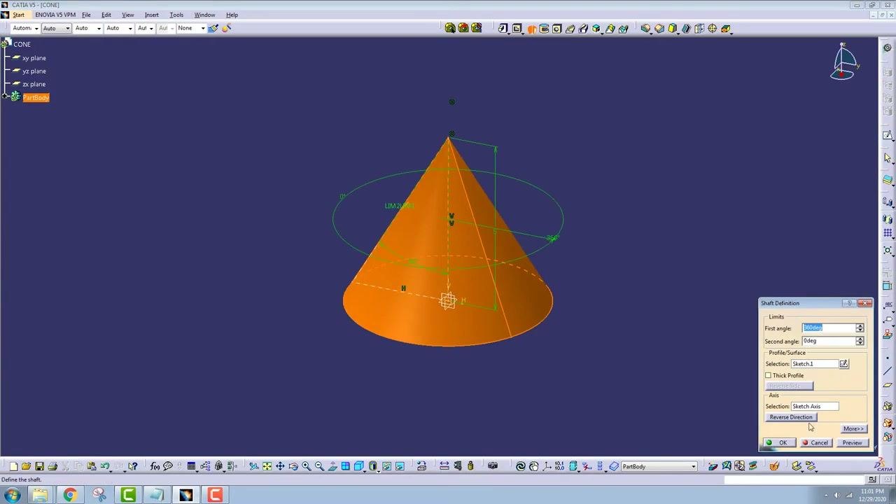
The Shaft tool creates a shaft by revolving a sketch around an axis. Select it, and the Shaft Definition dialog box appears. Set the following parameters:
- First angle: 360deg
- Second angle: 0deg
- Profile/Surface Selection: Sketch.1
- Axis Selection: Sketch Axis
If needed, select Reverse Direction. Click OK to generate the 3D cone.
The cone appears in orange, with green construction geometry and revolution indicators.
Inspect the 3D cone
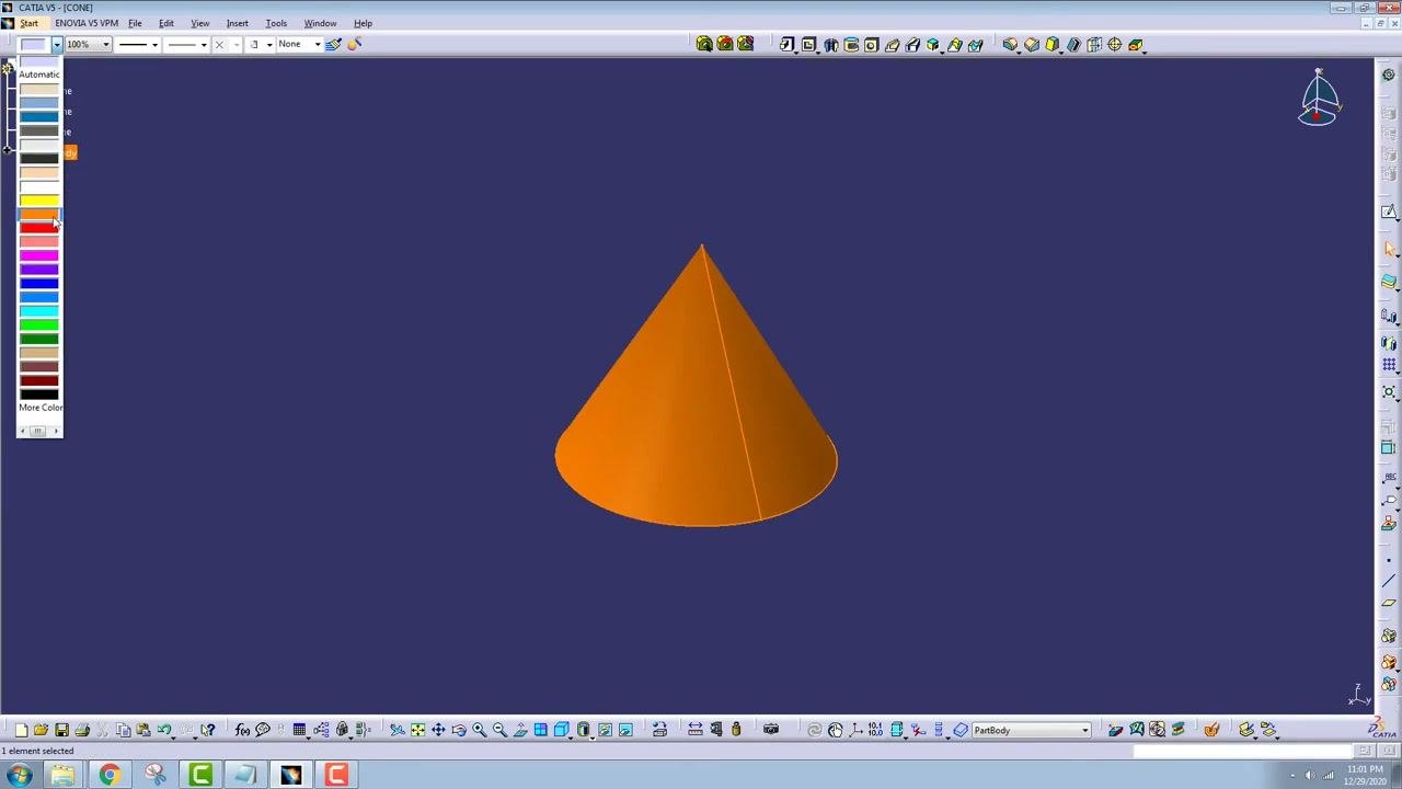
Rotate and zoom the view to inspect the cone. The cone appears in a shaded view, and the revolution path is visible as a dashed circle. The part tree on the left shows the updated structure, and the workspace is clear for further operations.
Check shading and lighting effects
Review the cone with enhanced shading. A visible shadow appears on the workspace floor, which indicates a change in the rendering mode or lighting settings.
The left panel lists the part structure: CONE with xy plane, yz plane, zx plane, and PartBody. The cone remains selected, and the workspace background is slightly lighter, which emphasizes the shadow.
Use this view to inspect the cone's surface quality and how it interacts with light. This is useful for presentation or further design evaluation.
Summary
You now know how to make a cone in CATIA V5. You started a new part in Part Design, sketched and constrained a right triangle profile, and exited the sketch. You then revolved the profile with the Shaft tool and inspected the resulting 3D cone, including its shading and shadow.
Generation details: cost, quality tiers
Docsie billed 1,500 credits ($1.05) to analyze this 3-minute video at standard quality. The rewrite, template fill and Word/PDF exports were included. The same video at each quality tier:
| Quality | Frames sampled | Credits | Approx. cost |
|---|---|---|---|
| Draft | every 16-30 s | 750 | $0.52 |
| Standard (this guide) | every 8-15 s | 1,500 | $1.05 |
| Detailed | every 4-7 s | 3,000 | $2.10 |
| Ultra | every 1-3 s | 6,000 | $4.20 |
Credits priced at $0.70 per 1,000; plans include a monthly allowance. Enterprise customers on on-premise or bring-your-own-model deployments run this on their own inference and pay no per-video credits.
Generated by Docsie Video-to-Docs on 2026-11-15 from a 2-minute video. Screenshots are frames from the source video and belong to their creator, 2D3D Technologies, whose original is embedded above. If you own this video and want the guide removed or credited differently, contact us and we will act within one business day.