
How to Fix Broken Links in CATIA
When you open a CATIA V5 assembly and some part files can't be found, the product structure loads incomplete and a warning appears. This guide shows how to fix broken links in CATIA by using the Desk command to relocate each missing part. It uses the radial engine assembly [8]FULL ASSEMBLY.CATProduct as the example. After the parts are reloaded, you inspect the constraints and review the product tree.
Video: HOW TO FIX BROKEN LINK IN CATIA by AUTOCAD & CATIA SOFTWARE VIDEOS (2026). All credit for the demonstration goes to the creator; watch the original on YouTube. The written guide below was generated from this video by Docsie. Creator? Request a change or removal.
When you open a CATIA V5 assembly and some part files can't be found, the product structure loads incomplete and a warning appears. This guide shows how to fix broken links in CATIA by using the Desk command to relocate each missing part. It uses the radial engine assembly [8]FULL ASSEMBLY.CATProduct as the example. After the parts are reloaded, you inspect the constraints and review the product tree.
Prerequisites
- CATIA V5 installed and running.
- The assembly file
[8]FULL ASSEMBLY.CATProduct. - The missing part files, stored in the folder
(9) RADIAL ENGINE ASSEMBLY.
Steps
Open the assembly and review the missing file warning
Open CATIA V5 and load [8]FULL ASSEMBLY.CATProduct. The product tree on the left lists the components: BASE, FIX BASED CYLINDER, multiple numbered cylinders, pistons, FIXED ROTATOR, CONNECTOR, MASTER ROD, and CONNECTING ROD.
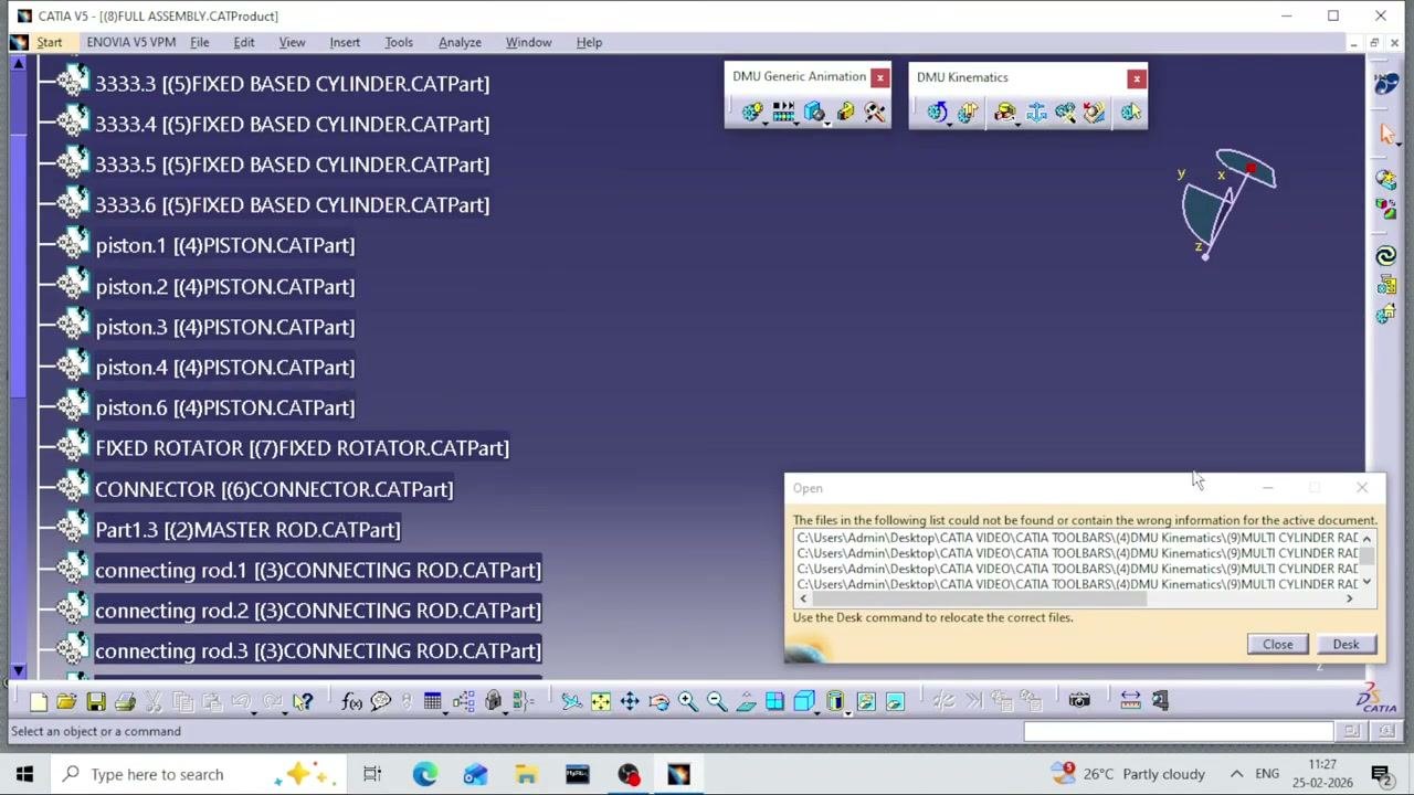
A yellow warning dialog appears at the bottom of the window. It reads "The files in the following list could not be found or contain the wrong information for the active document." The dialog lists the file paths of the missing or incorrect files and offers two options: Close and Desk.
The DMU Generic Animation and DMU Kinematics toolbars are visible at the top of the window.
Open Desk to start fixing broken links in CATIA
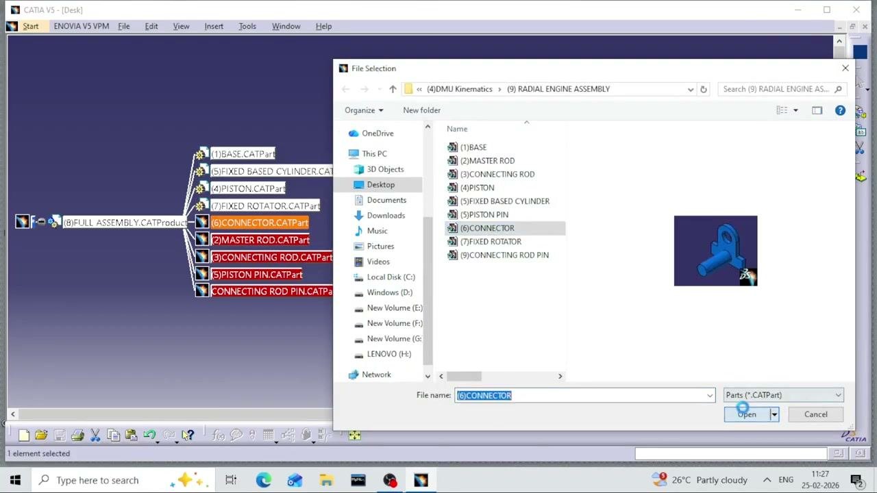
Click Desk in the warning dialog. The Desk window displays the assembly structure, and the missing parts are highlighted in red.
A File Selection dialog also appears. It shows the folder (9) RADIAL ENGINE ASSEMBLY.
Relocate the base part
Select (1)BASE from the list, then click Open to load the part.
Relocate the piston
Repeat the process for each remaining missing part. Select (4)PISTON, then click Open.
Relocate the connector
Select (6)CONNECTOR, then click Open.
Relocate the master rod
Select (2)MASTER ROD, then click Open.
Relocate the piston pin
Select (5)PISTON PIN, then click Open.
Inspect the constraints and fixes
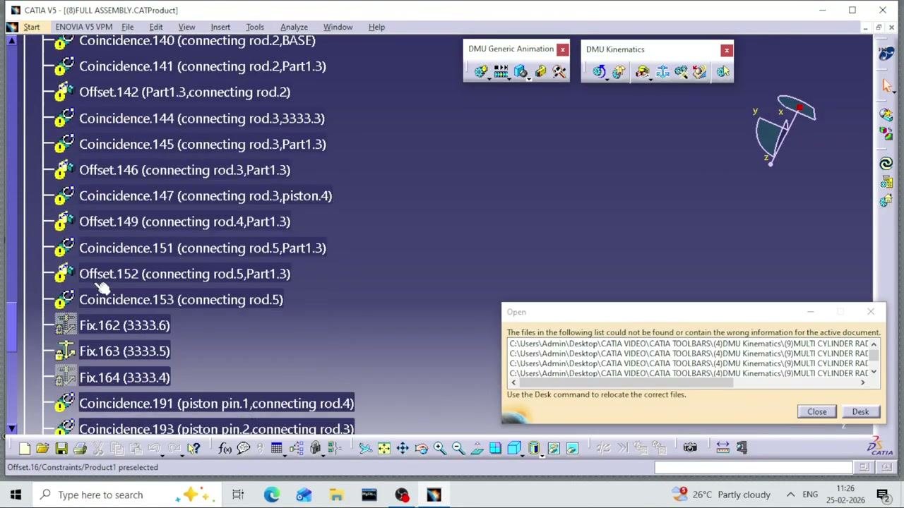
Switch to the constraints view in the assembly and review the list. You see:
- Coincidence and Offset constraints between various parts, such as connecting rods, pistons, and the base.
- Fix constraints for specific parts, such as Fix.162 (3333.6).
The warning dialog about missing files can remain visible while you review. The DMU toolbars and the axis triad (x, y, z) are still present.
Verify that all components are loaded
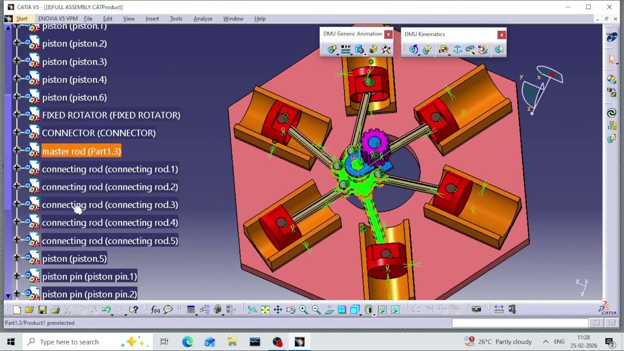
With [8]FULL ASSEMBLY.CATProduct open, check the product tree on the left. It should list:
- Pistons (piston.1 to piston.6)
- FIXED ROTATOR
- CONNECTOR
- Master rod (Part1.3)
- Connecting rods (connecting rod.1 to connecting rod.5)
- Piston pins (piston pin.1, piston pin.2)
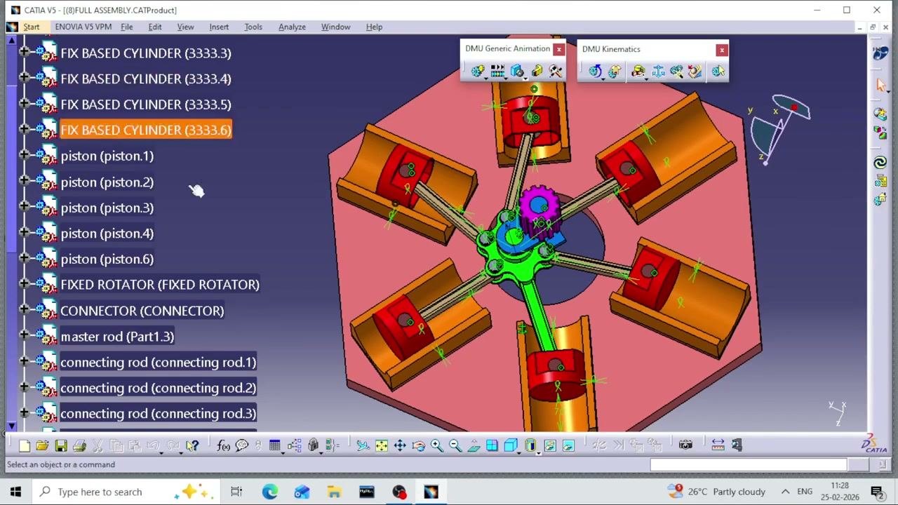
The 3D view in the center shows the fully assembled radial engine. Six pistons are arranged radially, each connected to the central master rod and rotator. Parts are color-coded for easy identification, and green symbols indicate active constraints.
Confirm the cylinder and base components
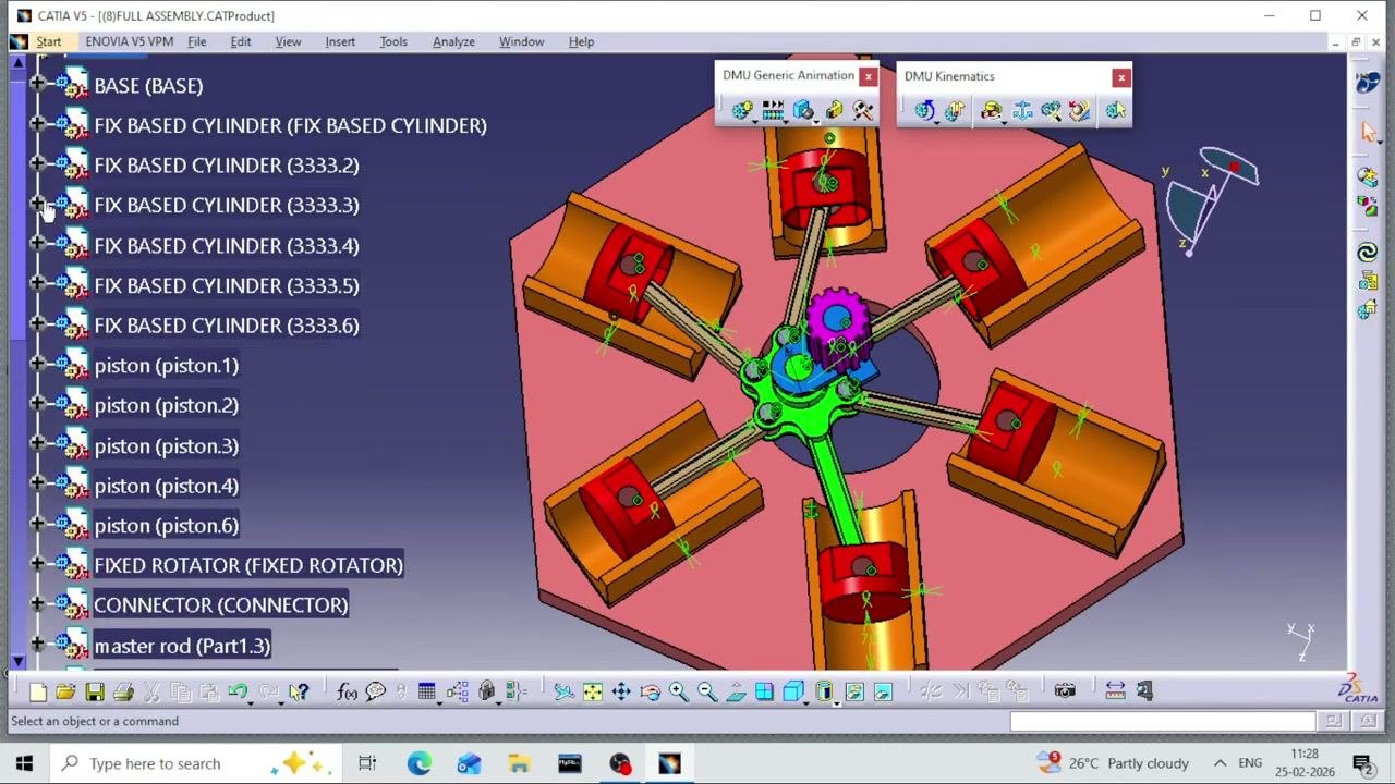
Scroll through the product tree to confirm that the cylinder and base components are present:
- BASE
- FIX BASED CYLINDER (multiple instances, 3333.2 to 3333.6)
Make sure all pistons (piston.1 to piston.6) are listed and visible in the 3D view. Confirm that the FIXED ROTATOR, CONNECTOR, and master rod are present and correctly named. The assembly looks unchanged, with all parts and constraints intact.
Collapse the product tree for clarity
Collapse or reorganize the product tree. Only the highest-level items remain visible: piston pins, Part1.1 to Part1.6, Constraints, and Applications.
The 3D view stays centered and unchanged, and the DMU toolbars and axis triad are still present. This organization helps prepare the assembly for simulation, documentation, or export.
Summary
You have fixed the broken links in the radial engine assembly by relocating each missing part through Desk. The assembly is fully loaded, all components are present, and the structure is ready for further work.
What's next
- Use the DMU Generic Animation and DMU Kinematics toolbars for simulation or analysis.
- Prepare the assembly for documentation or export.
Generation details: cost, quality tiers
Docsie billed 1,500 credits ($1.05) to analyze this 3-minute video at standard quality. The rewrite, template fill and Word/PDF exports were included. The same video at each quality tier:
| Quality | Frames sampled | Credits | Approx. cost |
|---|---|---|---|
| Draft | every 16-30 s | 750 | $0.52 |
| Standard (this guide) | every 8-15 s | 1,500 | $1.05 |
| Detailed | every 4-7 s | 3,000 | $2.10 |
| Ultra | every 1-3 s | 6,000 | $4.20 |
Credits priced at $0.70 per 1,000; plans include a monthly allowance. Enterprise customers on on-premise or bring-your-own-model deployments run this on their own inference and pay no per-video credits.
Generated by Docsie Video-to-Docs on 2026-11-15 from a 2-minute video. Screenshots are frames from the source video and belong to their creator, AUTOCAD & CATIA SOFTWARE VIDEOS, whose original is embedded above. If you own this video and want the guide removed or credited differently, contact us and we will act within one business day.