
How to Find the Center of Gravity in CATIA
You can find the center of gravity and mass of any part, sub-assembly, or full assembly in CATIA V5 with the Measure Inertia tool. This guide shows how to find the center of gravity in CATIA by building a simple assembly of two cylindrical parts and measuring it. The same technique applies to larger products, such as an automotive body.
Video: Catia V5 Powerful Tricks Collection #115|How to Find Centre of Gravity & Mass of Solid/Surface by howENGINEERSdoit! (2014). All credit for the demonstration goes to the creator; watch the original on YouTube. The written guide below was generated from this video by Docsie. Creator? Request a change or removal.
You can find the center of gravity and mass of any part, sub-assembly, or full assembly in CATIA V5 with the Measure Inertia tool. This guide shows how to find the center of gravity in CATIA by building a simple assembly of two cylindrical parts and measuring it. The same technique applies to larger products, such as an automotive body.
Prerequisites
Before you begin, make sure you have:
- CATIA V5 installed on your computer.
- A decision on whether to work with a single part or an assembly. This guide uses the assembly (top-down) approach.
Launch CATIA V5
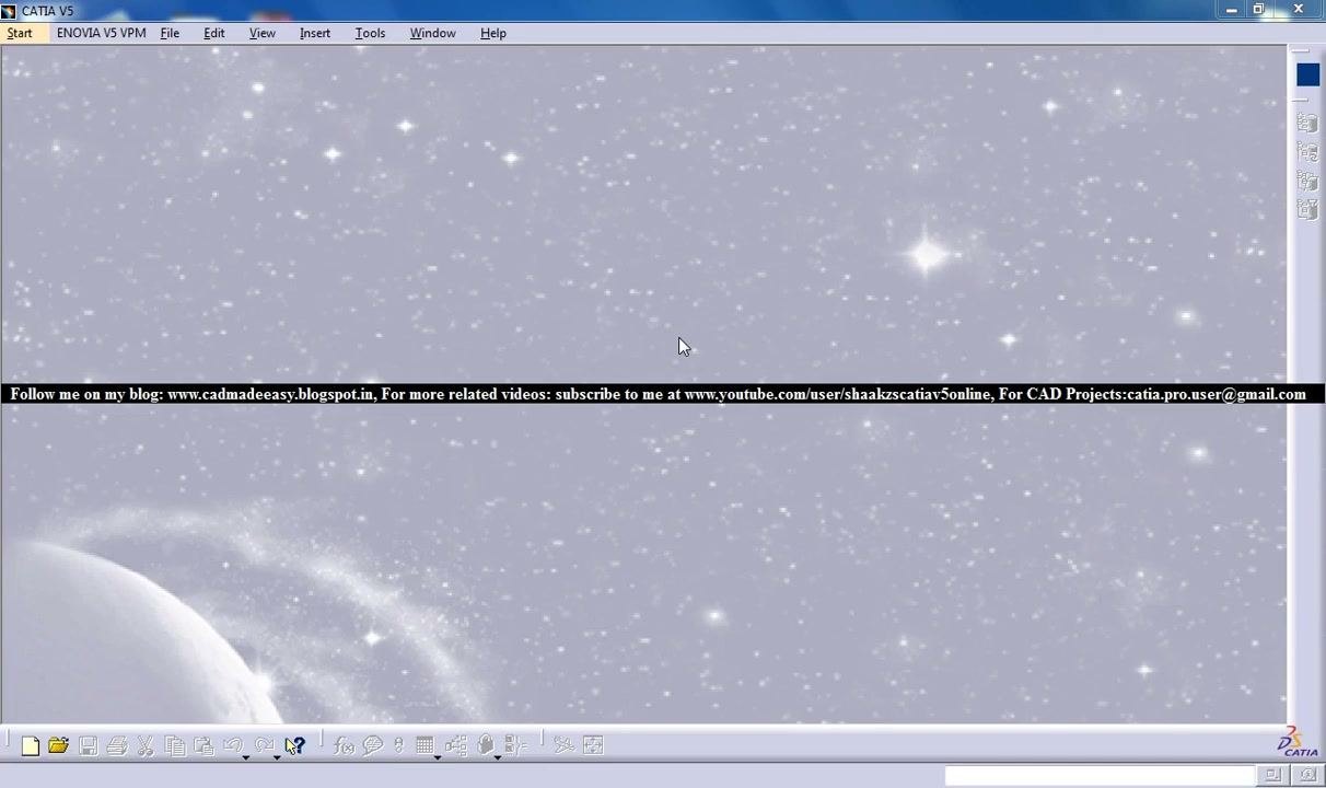
Open CATIA V5 and wait for the main interface to load. The background shows a starry sky, and a banner at the bottom links to additional resources.
Start a new assembly design
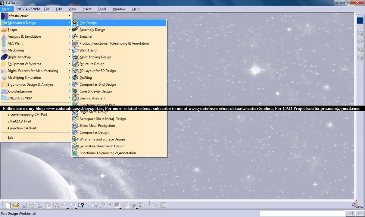
- Move your cursor to the top menu and click Start.
- Hover over Mechanical Design in the dropdown menu.
- Select Part Design to create a single part. To follow the top-down approach in this guide, select Assembly Design instead.
Insert a part and sketch the first cylinder
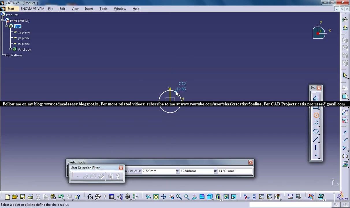
- In the assembly workbench, go to the Insert menu, choose New Part, and insert it under the current product.
- Confirm that the new part appears in the product tree on the left side of the screen.
- Select the new part (for example,
Part1) in the product tree. - Enter the sketcher workbench.
- Draw a circle to define the base of the cylinder. Use the sketch tools at the bottom of the screen.
- Specify the circle's dimensions. In this example, H is 7.723 mm and R is 14.991 mm.
You give the cylinder its height in a later step.
Add a second part
- Exit the current part workbench to return to the assembly workbench. The toolbars and available tools change when you switch workbenches.
- Select Insert > New Part.
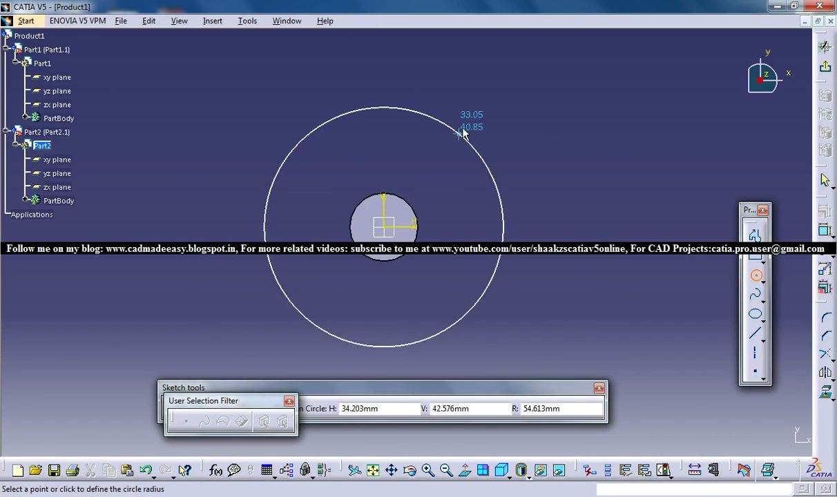
- Confirm that the new part (for example,
Part2) appears in the product tree underProduct1. - When the "New Part: Origin Point" dialog appears, click Yes to define a new origin point for the new part.
Sketch the second cylinder
- Enter the part workbench for
Part2. - Begin a new sketch on the plane you want, for example the
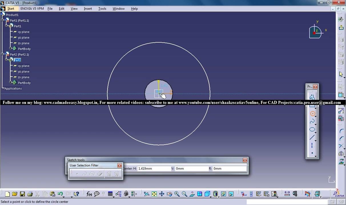
xy plane. - Draw a circle to define the base of the second cylinder.
- Specify the circle's dimensions, then complete the sketch and exit the sketcher.
The source gives two example sets of values:
- Center at H: 1.419 mm, V: 0 mm, Radius: 0 mm initially, then adjusted as needed.
- Circle at H: 34.203 mm, V: 42.576 mm, R: 54.613 mm.
Pad the second cylinder
- Use the Pad tool to extrude the circle into a cylinder.
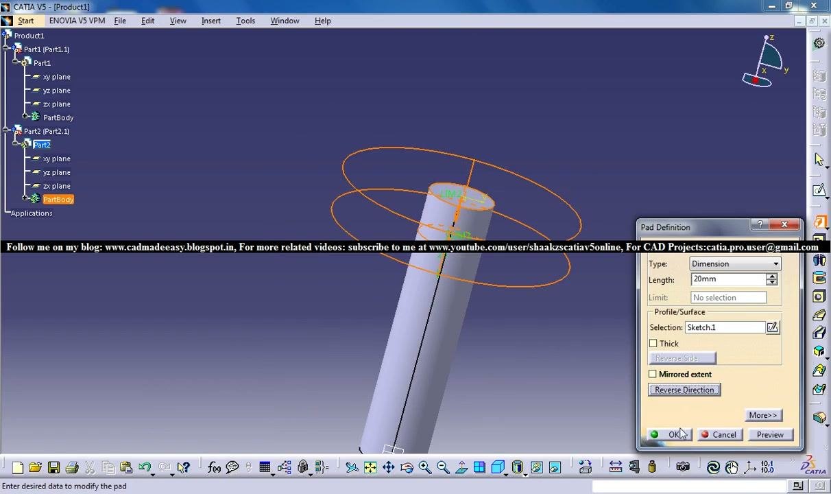
- In the Pad Definition dialog, set the length (height) of the cylinder. In this example, Length is 20 mm.
- Make sure the correct profile is selected (for example,
Sketch.1). - Click OK to create the pad.
Review the assembly
Rotate and inspect the assembly to confirm that both cylinders (Part1 and Part2) are present and correctly positioned. The product tree now shows both parts, each with its own body and planes.
Open the Measure Inertia tool
- Locate the Measure Inertia tool in the Measure toolbar.
- Click the Measure Inertia icon, a blue cube with a yellow arrow.
- Get ready to select the part or assembly whose center of gravity and mass you want to find.
Find the center of gravity and mass of the assembly
You can use this technique on any part, sub-assembly, or entire assembly. The Measure Inertia tool offers both 2D and 3D inertia calculations. This guide uses the 3D option.
- To measure a single part, click that part (for example,
Part1orPart2) in the product tree. - To measure the entire assembly, click the top-level product node (for example,
Product1). This analyzes the combined properties of all included parts.
To measure the assembly:
- With the Measure Inertia dialog open, make sure Measure Inertia 3D is selected.
- Click
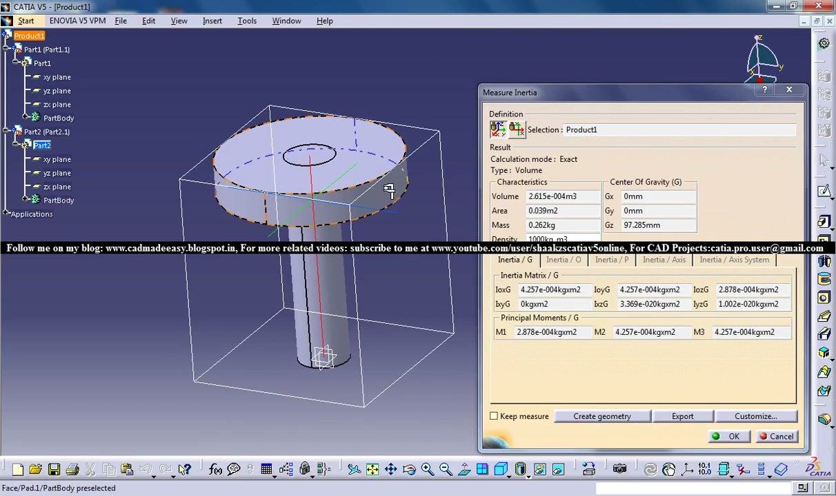
Product1in the product tree. - Look at the 3D view. A bounding box appears around the assembly, and a cross marks the calculated center of gravity.
Read the results
The Measure Inertia dialog displays these results for the assembly:
- Center of gravity (G): Gx = 0 mm, Gy = 0 mm, Gz = 97.285 mm
- Mass: 0.262 kg
- Density: 1000 kg/m³ (the default value used for the calculation)
- Volume: 2.615e-004 m³
- Area: 0.039 m²
The dialog also shows the inertia matrix and principal moments for advanced analysis.
The cross in the 3D view marks the exact location of the center of gravity. The coordinates (0, 0, 97.285) give that position in the assembly's coordinate system. The mass is calculated from the default density and the combined volume of the parts. You can use these results for further engineering analysis, design validation, or documentation.
Summary
You built an assembly of two cylindrical parts and used the Measure Inertia tool to find its center of gravity and mass in CATIA V5. The technique is quick and works on any part or assembly where you need mass properties, including automotive bodies and other mechanical assemblies.
What's next
- Adjust the density value in the part properties if you need results for materials other than the default.
- Select individual parts, sub-assemblies, or the top-level product to compare their centers of gravity and mass.
Generation details: cost, quality tiers
Docsie billed 3,000 credits ($2.10) to analyze this 6-minute video at standard quality. The rewrite, template fill and Word/PDF exports were included. The same video at each quality tier:
| Quality | Frames sampled | Credits | Approx. cost |
|---|---|---|---|
| Draft | every 16-30 s | 1,500 | $1.05 |
| Standard (this guide) | every 8-15 s | 3,000 | $2.10 |
| Detailed | every 4-7 s | 6,000 | $4.20 |
| Ultra | every 1-3 s | 12,000 | $8.40 |
Credits priced at $0.70 per 1,000; plans include a monthly allowance. Enterprise customers on on-premise or bring-your-own-model deployments run this on their own inference and pay no per-video credits.
Generated by Docsie Video-to-Docs on 2026-11-15 from a 5-minute video. Screenshots are frames from the source video and belong to their creator, howENGINEERSdoit!, whose original is embedded above. If you own this video and want the guide removed or credited differently, contact us and we will act within one business day.