
How to Extrude in CATIA
This guide shows you how to extrude in CATIA V5 using the Extruded Surface tool. You start with a new part and extrude a curved sketch into a surface. You then extrude a second sketch and set its limit with Up-to element, so it ends exactly at the curved surface.
Video: Extrude - CATIA V5 - CATIALOG by CATIALOG (2022). All credit for the demonstration goes to the creator; watch the original on YouTube. The written guide below was generated from this video by Docsie. Creator? Request a change or removal.
This guide shows you how to extrude in CATIA V5 using the Extruded Surface tool. You start with a new part and extrude a curved sketch into a surface. You then extrude a second sketch and set its limit with Up-to element, so it ends exactly at the curved surface.
Prerequisites
- CATIA V5 is installed and running.
- You can open a new part document.
- You can draw a spline or curve on a sketch plane.
Steps
Open a new part and check the workspace
Launch CATIA V5 and open a new part document. Before you start, confirm the workspace shows these elements:
- The tree on the left lists
Part2,xy plane,yz plane,zx plane, andPartBody. - The main grid area is ready for sketching.
- The User Selection Filter dialog is open, which lets you filter selectable entities.
No geometry exists yet.
Extrude a curved sketch into a surface
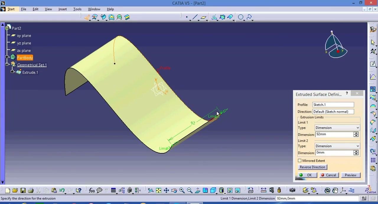
Draw a spline or curve on the sketch plane. Then select the Extruded Surface tool to generate a surface from the sketch.
The tree now shows Geometrical Set.1 and Extrude.1 under PartBody, and the Extruded Surface Definition dialog opens on the right. Set these parameters:
- Profile: Sketch.1
- Direction: Default (Sketch normal)
- Limit 1 Type: Dimension
- Limit 1 Dimension: 92 mm
- Limit 2 Type: Dimension
- Limit 2 Dimension: 0 mm
The preview displays a yellow, curved extruded surface.
Adjust the extrusion dimensions
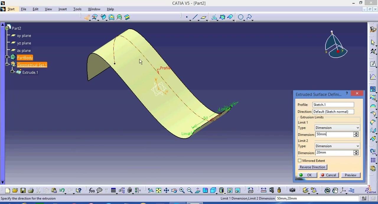
To change the size of the surface, edit the limits in the Extruded Surface Definition dialog:
- Limit 1 Dimension: 50 mm
- Limit 2 Dimension: 20 mm
The preview updates to reflect the new dimensions, and both the surface and its profile remain clearly visible.
Create a second sketch and extrude it
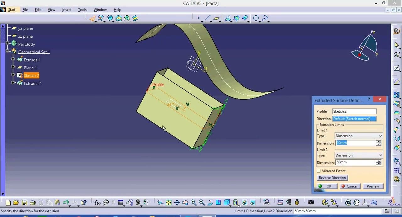
Add a new plane (Plane.1) and create a second sketch (Sketch.2) on it. Then use the Extruded Surface tool again to extrude the new sketch.
The tree now shows Plane.1, Sketch.2, and Extrude.2 under Geometrical Set.1. In the Extruded Surface Definition dialog, set:
- Profile: Sketch.2
- Direction: Default (Sketch normal)
- Limit 1 Type: Dimension
- Limit 1 Dimension: 50 mm
- Limit 2 Type: Dimension
- Limit 2 Dimension: 50 mm
The preview shows a rectangular solid extruded from the new sketch, positioned below the curved surface.
Rotate the view and check the solid's position
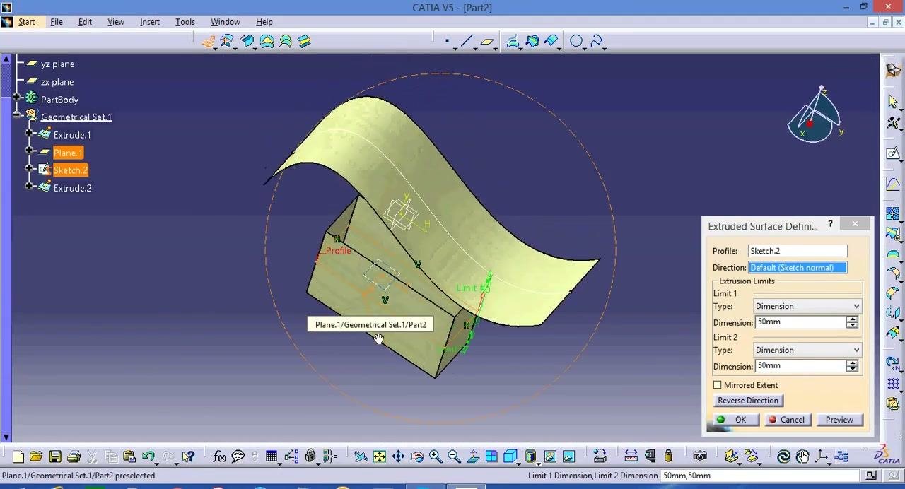
Rotate the view to inspect how the curved surface and the extruded solid relate to each other. Select Plane.1 to highlight its position relative to both. The Extruded Surface Definition dialog stays open, so you can keep adjusting the extrusion.
Extrude up to the curved surface with "Up-to element"
Use an advanced limit option to make the extrusion end precisely at another surface. In the Extruded Surface Definition dialog, set:
- Profile: Sketch.2
- Direction: Default (Sketch normal)
- Limit 1 Type: Up-to element
- Up-to element: Extrude.1 (select the curved surface you created earlier)
- Limit 2 Type: Dimension
- Limit 2 Dimension: 0 mm
The preview shows the extrusion extending exactly up to Extrude.1, where the solid intersects and ends at the surface. The tree lists Extrude.1, Plane.1, Sketch.2, and Extrude.2 under Geometrical Set.1.
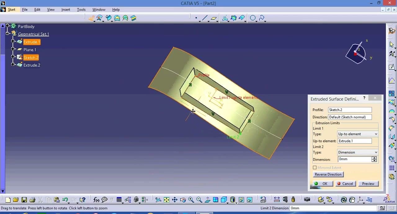
Rotate the model to inspect the intersection
Rotate the 3D view to examine where the extruded solid meets the curved surface. Confirm that the top face of the solid aligns with the curved surface. The red "Limit up-to element" annotation marks this limit.
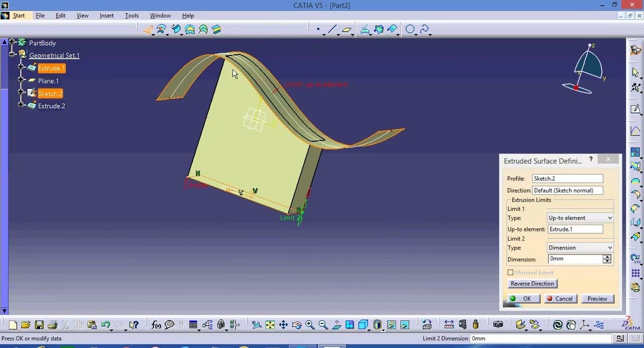
Verify the Limit 1 selection
In the Extruded Surface Definition dialog, check that Up-to element: Extrude.1 is selected for Limit 1. Clicking or highlighting the Extrude.1 entry confirms the selection. The preview stays the same, with the solid ending at the curved surface.
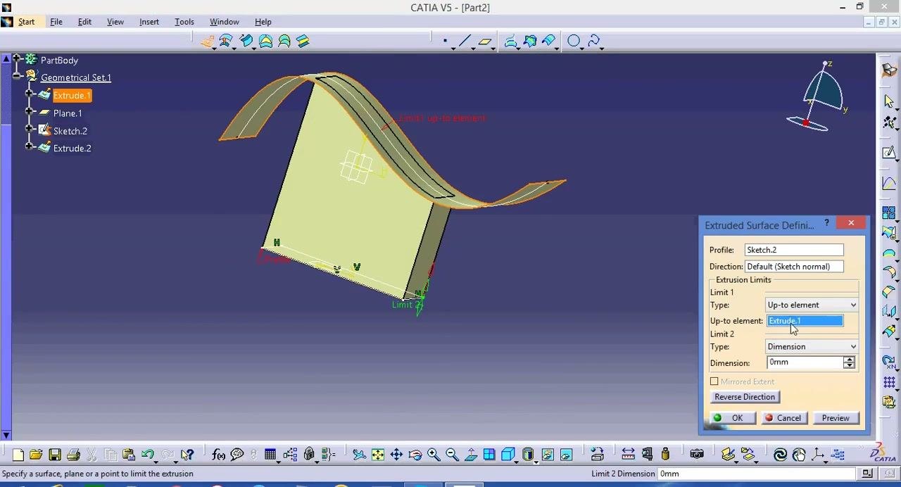
Review the parameters and apply the extrusion
Review all parameters in the Extruded Surface Definition dialog:
- Profile: Sketch.2
- Direction: Default (Sketch normal)
- Limit 1: Up-to element (Extrude.1)
- Limit 2: Dimension (0 mm)
Click OK to apply the extrusion. The workspace now shows the completed solid, bounded by the curved surface and ready for further modeling or analysis.
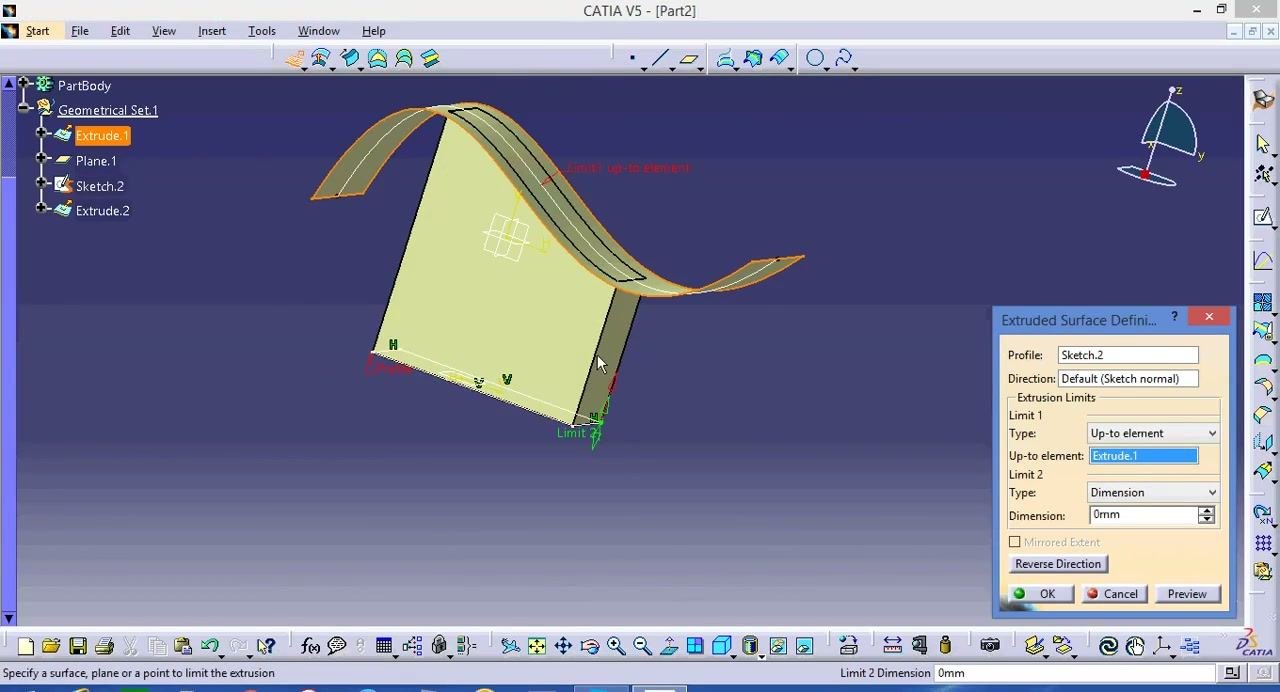
Summary
You now know how to extrude in CATIA V5 with the Extruded Surface tool. You extruded a curved sketch with dimension limits and adjusted those limits. You then extruded a second sketch and used Up-to element so it ends exactly at the existing curved surface.
Generation details: cost, quality tiers
Docsie billed 1,500 credits ($1.05) to analyze this 3-minute video at standard quality. The rewrite, template fill and Word/PDF exports were included. The same video at each quality tier:
| Quality | Frames sampled | Credits | Approx. cost |
|---|---|---|---|
| Draft | every 16-30 s | 750 | $0.52 |
| Standard (this guide) | every 8-15 s | 1,500 | $1.05 |
| Detailed | every 4-7 s | 3,000 | $2.10 |
| Ultra | every 1-3 s | 6,000 | $4.20 |
Credits priced at $0.70 per 1,000; plans include a monthly allowance. Enterprise customers on on-premise or bring-your-own-model deployments run this on their own inference and pay no per-video credits.
Generated by Docsie Video-to-Docs on 2026-11-15 from a 2-minute video. Screenshots are frames from the source video and belong to their creator, CATIALOG, whose original is embedded above. If you own this video and want the guide removed or credited differently, contact us and we will act within one business day.