
How to Do Drafting in CATIA
This guide shows you how to do drafting in CATIA V5. You start with a 3D part, create a 2D drawing sheet, and place standard views. You then format annotations, show hidden lines and centerlines, and adjust view scale. Finally, you add dimensions, notes, an isometric view, and a title block.
Video: CATIA Drafting / Drawing Tutorial for Beginners - 1 by CAD CAM Tutorials (2018). All credit for the demonstration goes to the creator; watch the original on YouTube. The written guide below was generated from this video by Docsie. Creator? Request a change or removal.
This guide shows you how to do drafting in CATIA V5. You start with a 3D part, create a 2D drawing sheet, and place standard views. You then format annotations, show hidden lines and centerlines, and adjust view scale. Finally, you add dimensions, notes, an isometric view, and a title block.
Prerequisites
- CATIA V5 installed on your computer.
- A 3D part file to draft, such as Pin, Flange, Plate, or Vertical Plate. The examples store these in
Documents\CATIA.
Prepare the model for drafting
Step 1. Launch CATIA V5
Launch CATIA V5 and confirm you are on the main screen. Make sure the workspace is clear and ready for a new operation.
Step 2. Open the 3D part
Click the Open icon, or select File > Open. In the file selection dialog, go to the folder that contains your 3D part files, for example Documents\CATIA. Select the part you want to draft (for example, Pin, Flange, or Plate), then click Open.
Step 3. Switch to isometric view and start the Drafting workbench
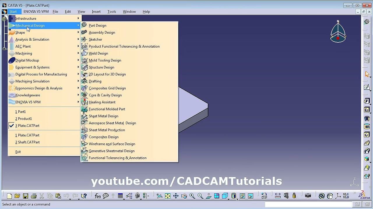
Set the model to isometric view for better visualization. Then click the Start menu in the top left and hover over Mechanical Design to expand its submenu. Select Drafting from the list of modules.
Create the drawing sheet
Step 4. Choose a drawing sheet configuration
In the New Drawing Creation dialog, choose your layout. You can start with an empty sheet and add views manually. You can also choose a preset such as All Views, Front, Bottom, and Right, or Front, Top, and Left. This tutorial uses Front, Top, and Left.
Step 5. Set the sheet standard and size
In the same dialog, click Modify to adjust the sheet settings:
- Set Standard to ISO.
- Set Sheet Size to A3 (297 x 420 mm).
- Set the orientation to Landscape.
Click OK to confirm.
Step 6. Position the views on the sheet
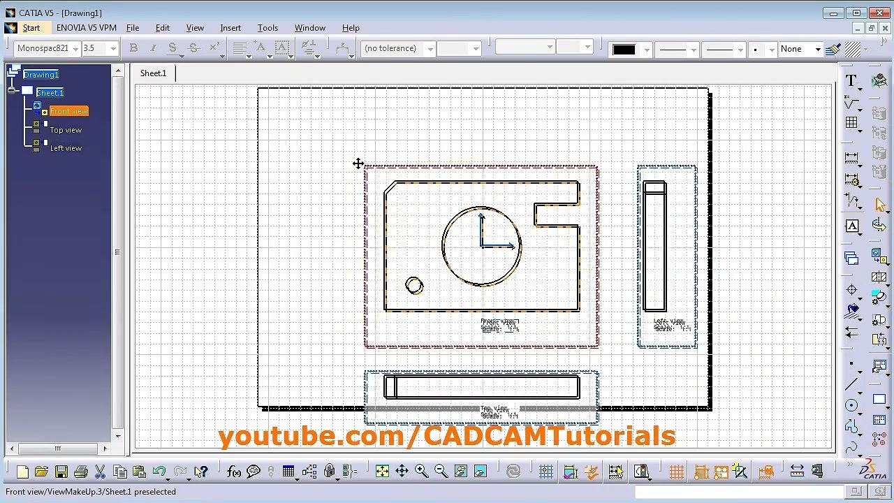
The sheet displays the selected Front, Top, and Left views. Click and drag the views to position them as you like.
The views are interlinked. Moving the main view moves the associated views with it, and you can move side views only horizontally.
Format labels and annotations
Step 7. Adjust and format view labels
Select a label, such as Front View, under the view you want to change. In the text editor, change the font, increase the font size, or apply bold or italic formatting. Click OK to confirm.
Step 8. Move and format annotations
Click and hold the left mouse button on an annotation, such as a view label or scale text, and drag it to a new location.
To remove the scale annotation, double-click the scale text (for example, "Scale: 1:1") under the view. Delete its content in the text editor.
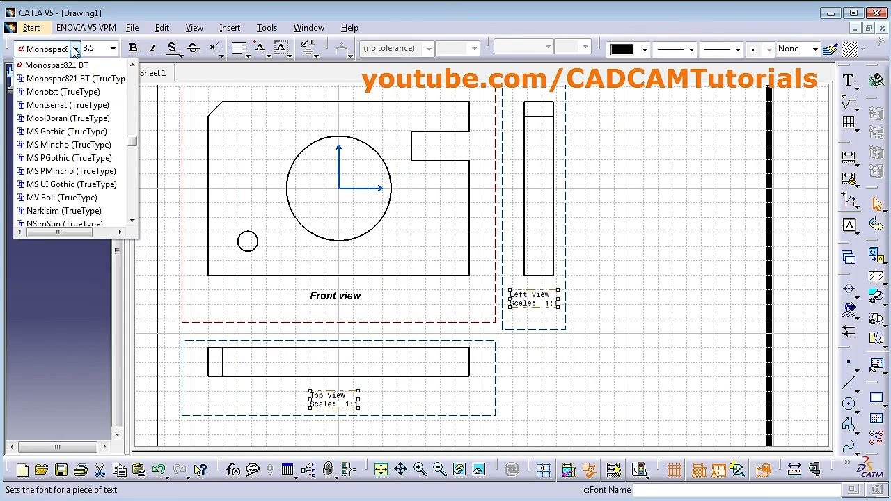
To change an annotation's formatting, double-click it to open the text editor and select the text. Choose a different font from the font dropdown and adjust the size, bold, italic, and other options. Click OK to apply the changes.
To format several annotations at once, hold Ctrl and click each annotation. Then apply the font, size, bold, or italic formatting to all of them together.
Control view display and scale
Step 9. Display hidden lines and centerlines
First, hold Ctrl and select all the views you want to modify. The selected views are highlighted in orange in the tree and on the sheet.
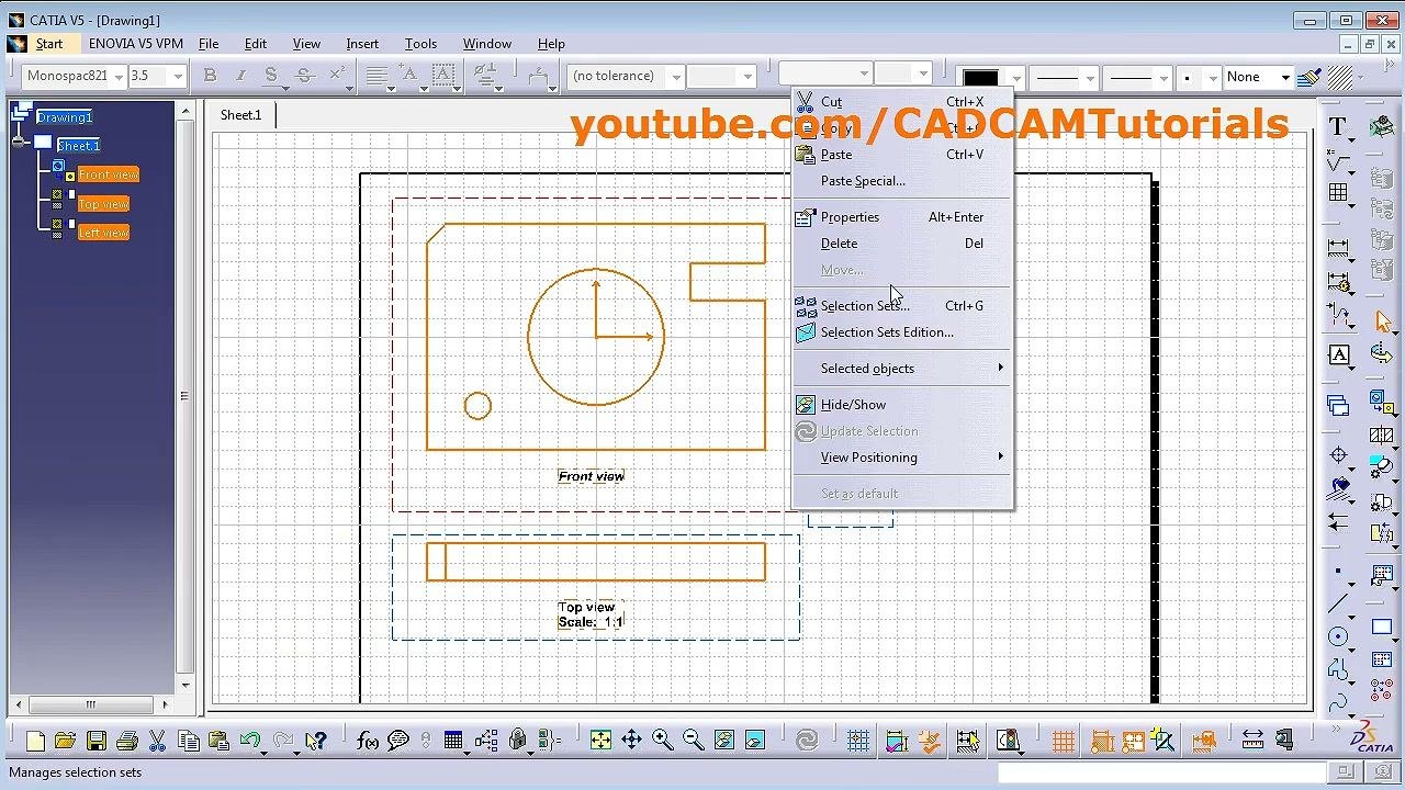
Right-click any selected view and choose Properties. In the Properties dialog, open the View tab and find the Dress-up section. Check Hidden Lines, Center Line, Axis, and Thread as needed.
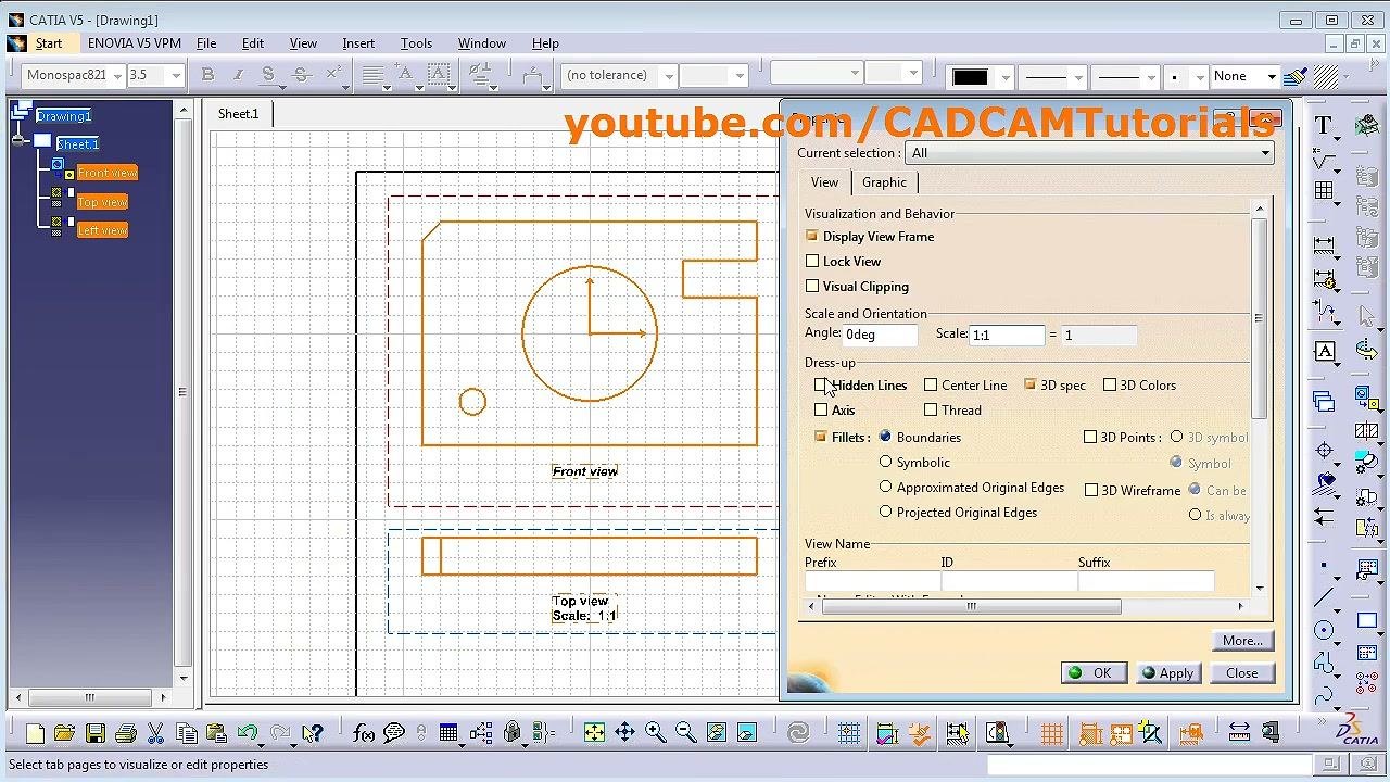
Click Apply or OK to confirm and close the dialog.
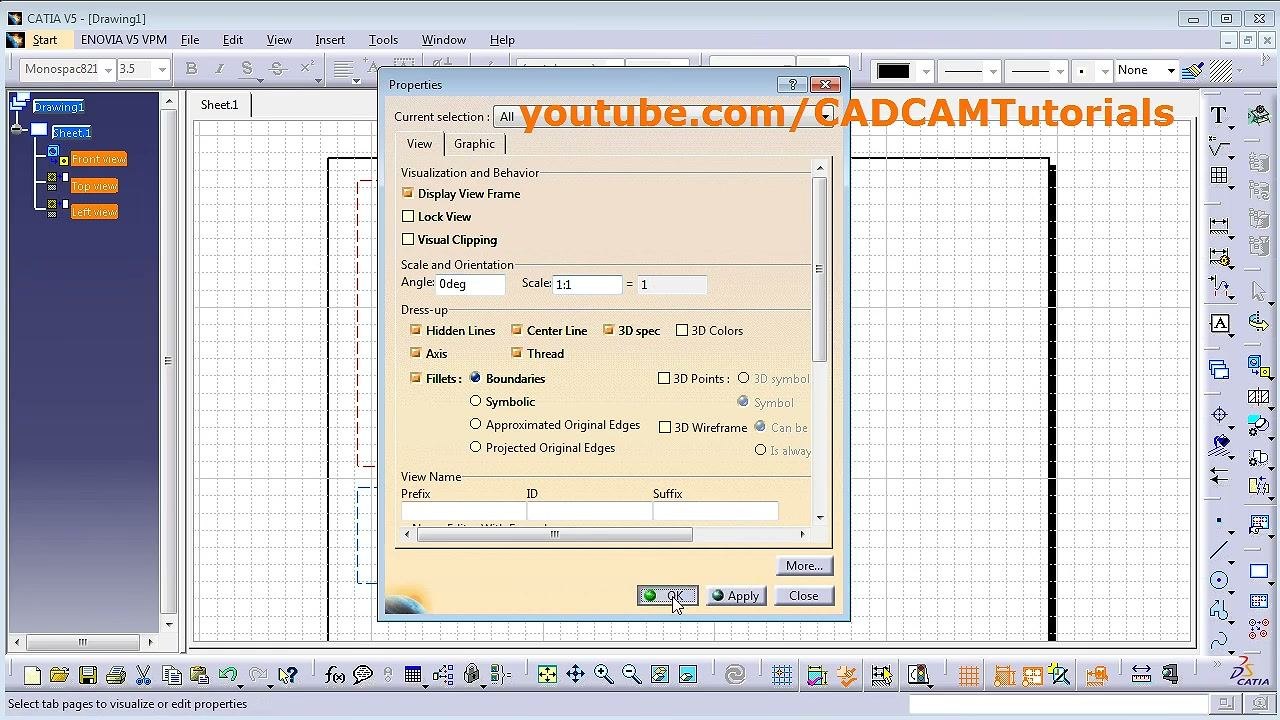
Step 10. Adjust the scale of drawing views
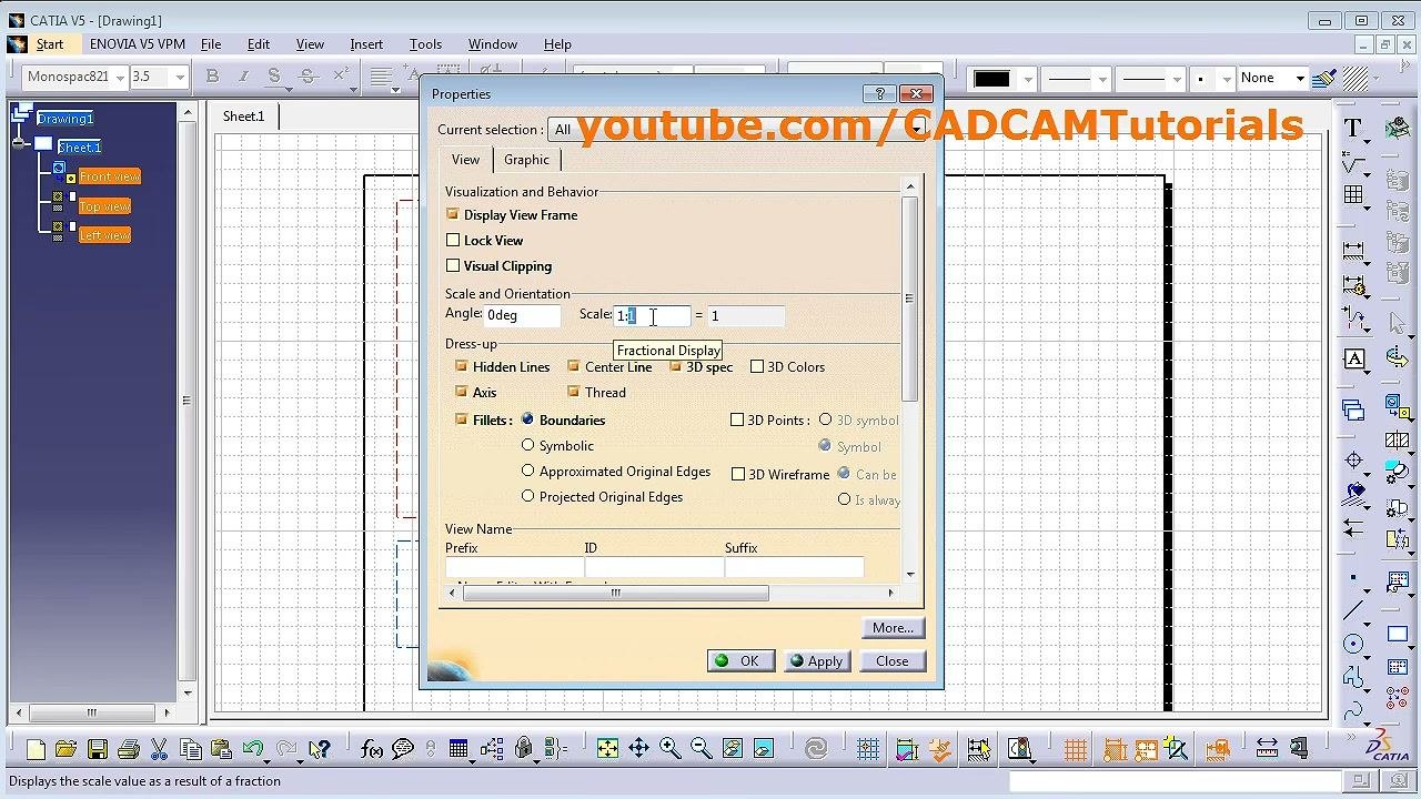
Open the Properties dialog as in the previous step and find the Scale field under Scale and Orientation. A higher ratio enlarges the view, and a lower ratio reduces it:
- Setting the scale to
2:1doubles the view size. - Setting the scale to
1:2makes the view half its original size.
Click Apply or OK to update the view scale.
Generate dimensions automatically
Step 11. Display the generated dimensions
Find the Generate Dimensions tool on the right toolbar (the icon with a dimension symbol) and click it. The Generated Dimension Analysis dialog appears and lists the part and the number of constraints and dimensions. Click OK to display all the generated dimensions on your drawing views.
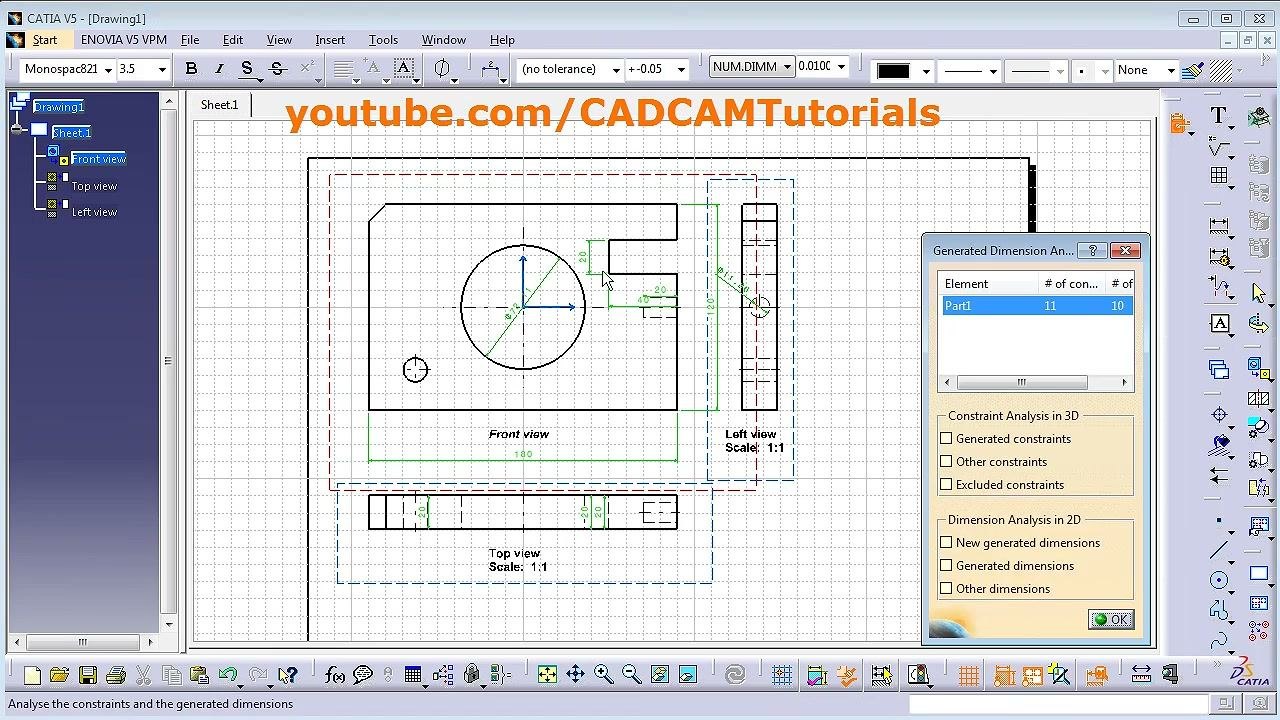
Step 12. Arrange and clean up dimensions
To reposition a dimension, press and hold the left mouse button on it and drag it to a new location on the sheet.
To align diameter values horizontally:
- Hold
Ctrland select the diameter dimensions you want to align. - Right-click one of them and choose Properties.
- Click the Dimension Line tab.
- Under Representation, select the two-part horizontal option.
- Click OK.
- Click outside the dialog, then drag the diameter dimensions to your preferred positions.
To remove duplicate or unnecessary dimensions, select them and press Delete. For example, you can delete a "20" dimension that appears three times.
Step 13. Add an isometric view
Click the Isometric View tool, typically in the view creation toolbar, and select Isometric View in the prompt that appears. Click the drawing sheet where you want to place the view. In the window that opens, choose your part (for example, "Part1" or "Plate") and select the orientation you want.
Add a frame and title block
Step 14. Create the title block
Open the Manage Frame And Title Block dialog. Set Style of Title Block to Drawing Titleblock Sample 1 and set Action to Create. Click Apply, then OK. The sheet now displays the title block and border.
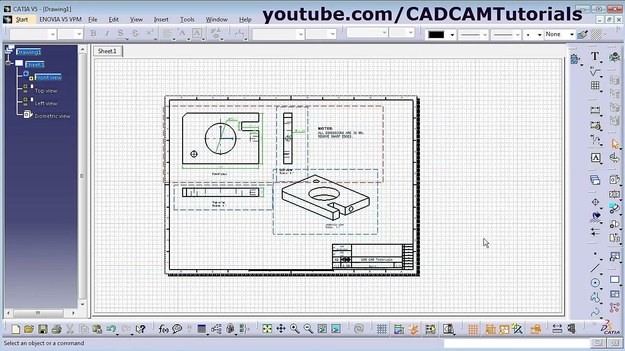
Step 15. Edit the title block text
Double-click the title block area to open the Text Editor. Enter the text you want, for example "CAM CAM Tutorials", and click OK to save.
Add and set up a second sheet
Step 16. Add a new sheet
In the tree on the left, right-click to add a new sheet (Sheet.2). The new sheet appears as a blank drawing area with a grid background.
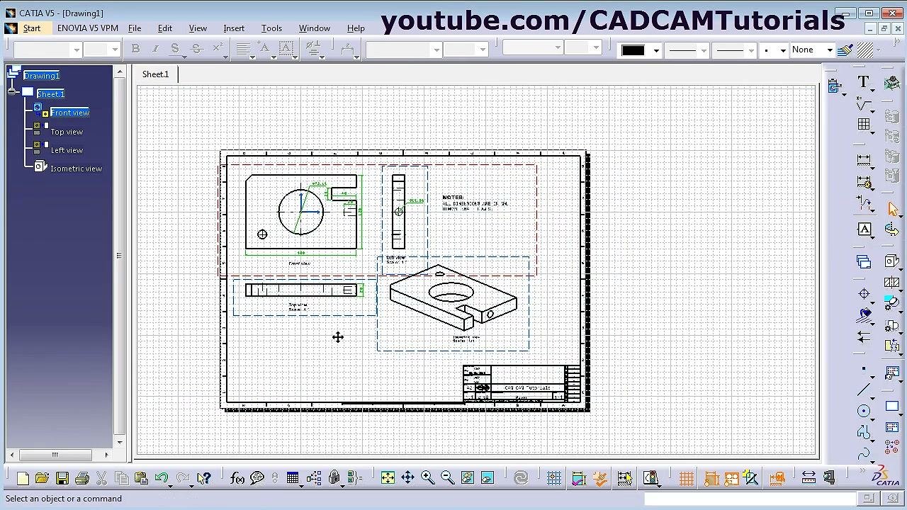
Step 17. Set the sheet properties
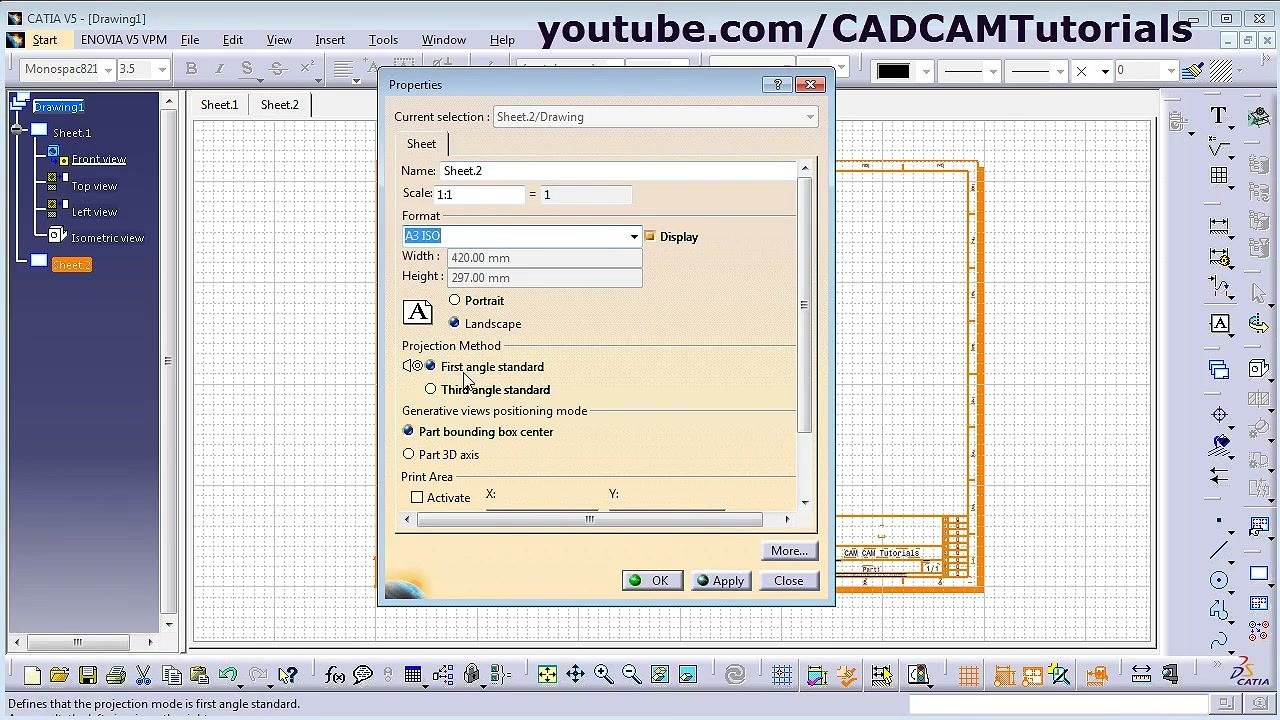
In the Properties dialog for Sheet.2, set the following:
- Name: Sheet.2
- Scale: 1:1
- Format: A3 ISO (Width: 420.00 mm, Height: 297.00 mm)
- Orientation: Portrait or Landscape, as needed
- Projection Method: First angle standard or Third angle standard, as required
- Generative views positioning mode: Part bounding box center
Click OK to apply the settings.
Step 18. Open the sheet background
To add a frame and title block to the new sheet, go to the Edit menu and select Sheet Background. This lets you modify the background elements of the sheet.
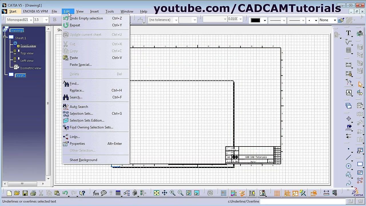
Step 19. Add the frame and title block to the new sheet
Open the Manage Frame And Title Block dialog for the new sheet. Set Style of Title Block to Drawing Titleblock Sample 1. Under Action, select Create or Resize, as needed. Click Apply, then OK to update the frame and title block.
Draft another part manually
Step 20. Open another part
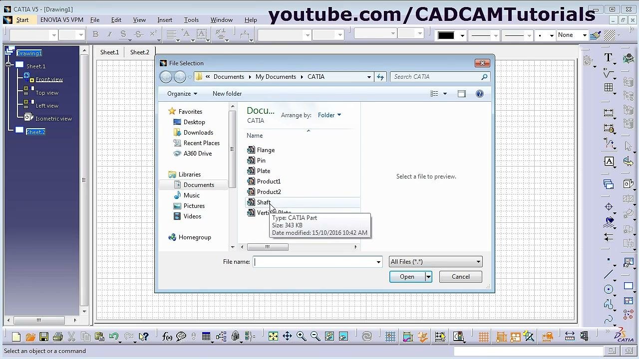
To create a drawing for another part, select File > Open or click the open icon. In the file selection dialog, go to the folder with your CATIA parts and select the part file, for example "Vertical Plate.CATPart". Click Open to load it.
Step 21. Return to the drawing sheet
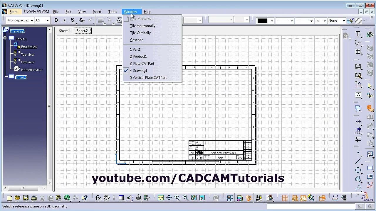
Click the Window menu and select your drawing document (for example, "Drawing1") to return to the drawing environment. Make sure the correct sheet, such as Sheet.2, is active and visible.
Step 22. Select the front view face
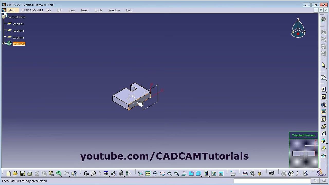
In the part window (for example, "Vertical Plate.CATPart"), locate the 3D model. Click the face you want as the front view. For example, select the large flat face if you want that side in front. The selected face is highlighted, and a reference plane may appear to show your selection.
Insert views and add details manually
Step 23. Add a projection view
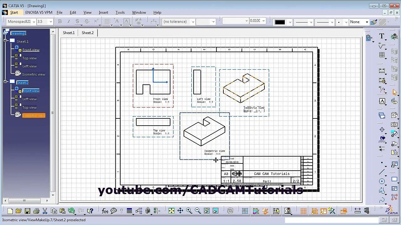
Click the Projection View tool on the right-side toolbar. Move the cursor next to the front view and click to place the left view. The new left view appears aligned with the front view, and the tree shows "Left view" under Sheet.2.
Step 24. Add more projection views and an isometric view
Click Projection View again and place a top view below the front view. The tree now lists "Front view", "Left view", and "Top view" under Sheet.2. Each view is labeled with its name and scale (for example, "Scale: 1:1").
To add an isometric view, click the Isometric View tool on the right-side toolbar. Move the cursor to the location you want.
Step 25. Place and arrange the isometric view
Click to place the isometric view on the sheet, then move and arrange the views for clarity. Select any view to access options for hiding elements or adding centerlines. The drawing now shows the front, left, top, and isometric views.
Step 26. Add dimensions manually
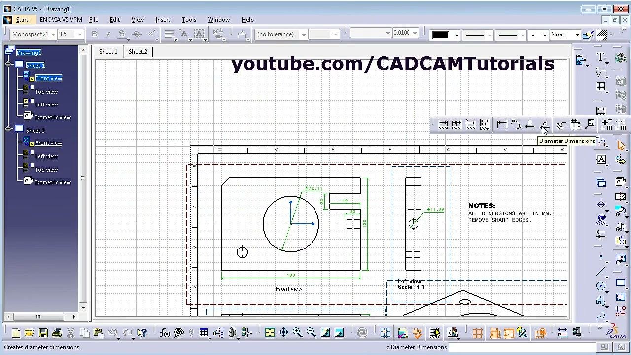
Use the dimensioning tools on the right-side toolbar. For a diameter, select the appropriate tool (for example, Diameter Dimensions) and click the circle or arc you want to dimension. The dimension appears in green with its value, such as "Ø72.11". Zoom in for precise placement.
Step 27. Add radius or chamfer dimensions
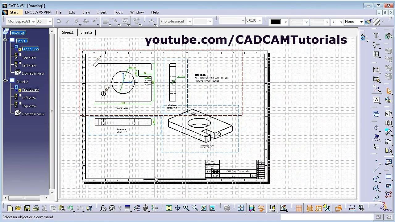
For a radius, select the Radius Dimension tool (often marked "R") and click the arc or circle. For a chamfer, select the Chamfer Dimension tool and click the chamfered edge. Adjust the position of each dimension for clarity.
Step 28. Add notes
Use the text tool to add notes to the drawing, for example "ALL DIMENSIONS ARE IN MM. REMOVE SHARP EDGES." Place notes in a clear area, typically near the views or in a designated notes section. Include all the details and instructions needed for manufacturing or inspection.
Step 29. Detail multiple parts on one sheet
To detail another part on the same sheet, repeat the process. Open the part file and use the Front view, Projection View, and Isometric View tools to place its views. Add dimensions and notes as required. Organize the views and notes clearly so several parts fit on one sheet.
Review the completed drawing
Step 30. Check the sheet and save
Examine the sheet to confirm all required views and details are present:
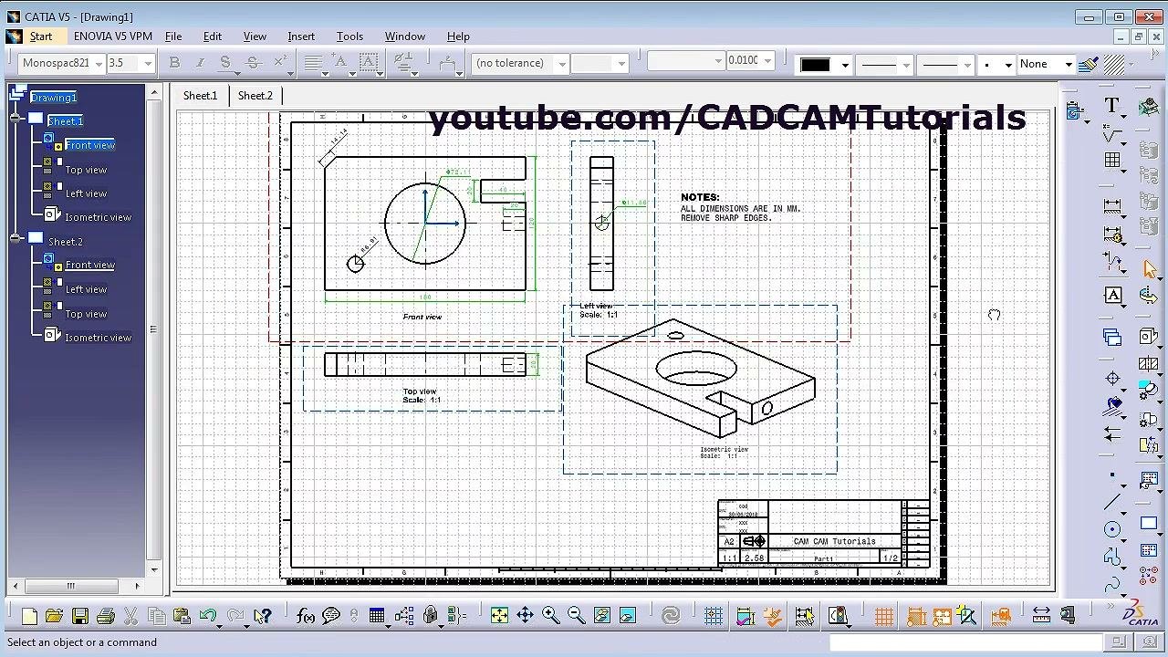
- The front view (top left), left view (upper center), top view (bottom center), and isometric view (bottom right) are placed and labeled with their scales, such as "Scale: 1:1".
- Each view is enclosed in a dashed colored box.
- Dimensions appear in green, such as the diameter and length values in the front and left views.
- The note reads: "NOTES: ALL DIMENSIONS ARE IN MM. REMOVE SHARP EDGES."
- The title block at the bottom right shows details such as sheet size (A2 in the example), scale (1:1), part name, and drawing number.
- The tree on the left shows Drawing1 with Sheet.1 (its own set of views) and Sheet.2 (active, with Front, Left, Top, and Isometric views).
Confirm that all annotations, notes, and dimensions are legible and correctly placed. Make sure no views or text overlap and that the title block contains the information needed for manufacturing or inspection. Save the drawing file to preserve your work.
Summary
You now know how to do drafting in CATIA V5. You created a drawing from a 3D model, configured the sheet, and formatted labels and annotations. You also displayed hidden lines and centerlines, adjusted view scale, and generated and arranged dimensions. Finally, you added title blocks, extra sheets, manual views, and notes. The result is a complete drawing sheet ready for production or review.
What's next
- Repeat the manual view workflow to draft additional parts on new sheets.
- Try the other preset configurations, such as All Views or Front, Bottom, and Right, when you create a drawing.
Generation details: cost, quality tiers
Docsie billed 6,000 credits ($4.20) to analyze this 12-minute video at standard quality. The rewrite, template fill and Word/PDF exports were included. The same video at each quality tier:
| Quality | Frames sampled | Credits | Approx. cost |
|---|---|---|---|
| Draft | every 16-30 s | 3,000 | $2.10 |
| Standard (this guide) | every 8-15 s | 6,000 | $4.20 |
| Detailed | every 4-7 s | 12,000 | $8.40 |
| Ultra | every 1-3 s | 24,000 | $16.80 |
Credits priced at $0.70 per 1,000; plans include a monthly allowance. Enterprise customers on on-premise or bring-your-own-model deployments run this on their own inference and pay no per-video credits.
Generated by Docsie Video-to-Docs on 2026-11-15 from a 11-minute video. Screenshots are frames from the source video and belong to their creator, CAD CAM Tutorials, whose original is embedded above. If you own this video and want the guide removed or credited differently, contact us and we will act within one business day.