
How to Create Parameters in CATIA
This guide shows how to create parameters in CATIA V5 and use them to drive a sketch and a 3D pad. You start with a rectangle in the Sketcher, then create length parameters with multiple values and a radius parameter in the Formulas dialog. You then link each parameter to a sketch dimension and change the values to update the model.
Video: How to define parameters in Catia V5 by alina (2018). All credit for the demonstration goes to the creator; watch the original on YouTube. The written guide below was generated from this video by Docsie. Creator? Request a change or removal.
This guide shows how to create parameters in CATIA V5 and use them to drive a sketch and a 3D pad. You start with a rectangle in the Sketcher, then create length parameters with multiple values and a radius parameter in the Formulas dialog. You then link each parameter to a sketch dimension and change the values to update the model.
Prerequisites
- CATIA V5 is installed and running.
- You can create a new part and open the Sketcher workbench.
Steps
Open a new part
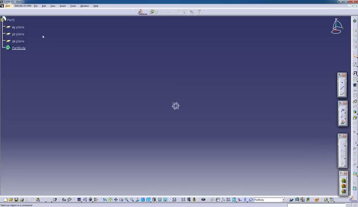
Launch CATIA V5 and create a new part. The tree on the left shows Part1, xy plane, yz plane, zx plane, and PartBody. The main area is empty and ready for sketching.
Draw a rectangle in the Sketcher
Enter the Sketcher workbench and select a plane, such as xy plane. Draw a rectangle in the sketch area. The rectangle is centered on the origin, with green constraint points at the corners.
Apply dimensional constraints
Add dimensional constraints to the rectangle:
- Set the horizontal length to
180mm. - Set the vertical height to
70mm.
The constraints appear in green above and to the right of the rectangle.
Add a corner radius and accept the conversion
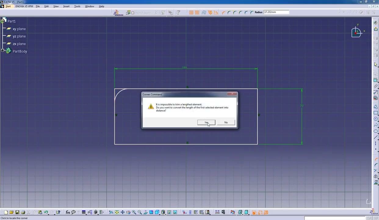
Select the corner tool and try to add a radius to one corner of the rectangle. A warning dialog appears with this message: "It is impossible to trim a lengthed element. Do you want to convert the length of the first selected element into distance?" Click Yes to proceed.
Open the Formulas dialog
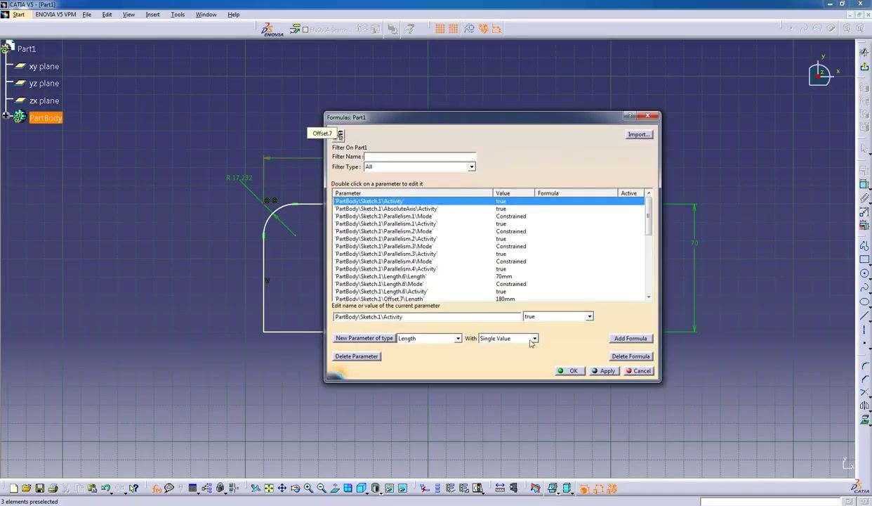
Open the Formulas dialog to manage the parameters of the part. The dialog lists all parameters, including constraints and activities, such as PartBody\Sketch.1\Activity. Double-click a parameter to edit its value or formula.
Create a parameter with multiple values
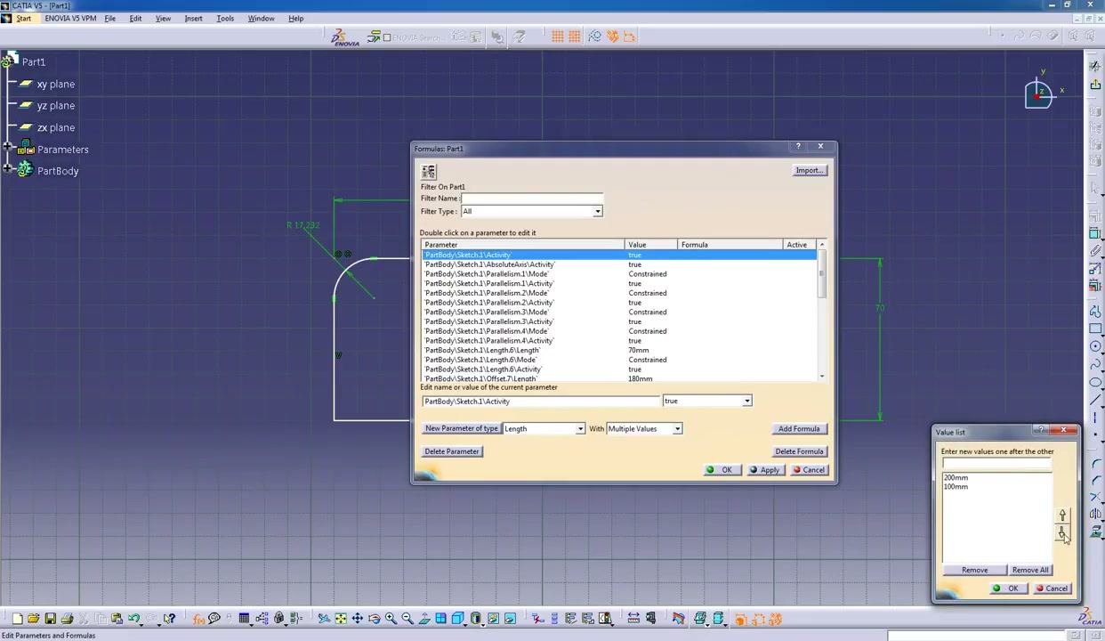
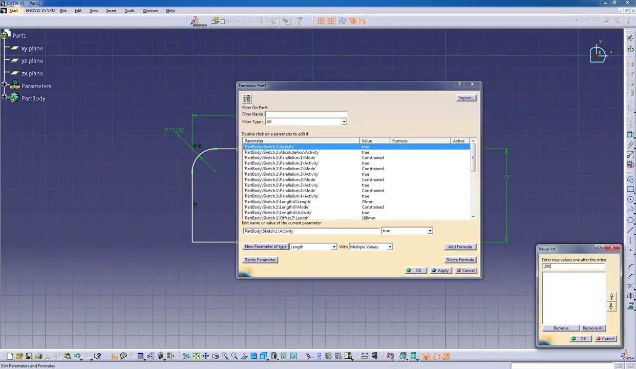
This is the first step in how to create parameters in CATIA that offer a choice of values. In the Formulas dialog, create a new parameter of type Length with Multiple Values. A Value list dialog appears. Enter these values:
200mm100mm
Click OK to confirm.
Confirm and apply the first parameter
The new parameter, First parameter, appears in the parameter tree with the value 200mm. Click OK or Apply in the Formulas dialog to save your changes.
Add a second parameter with multiple values
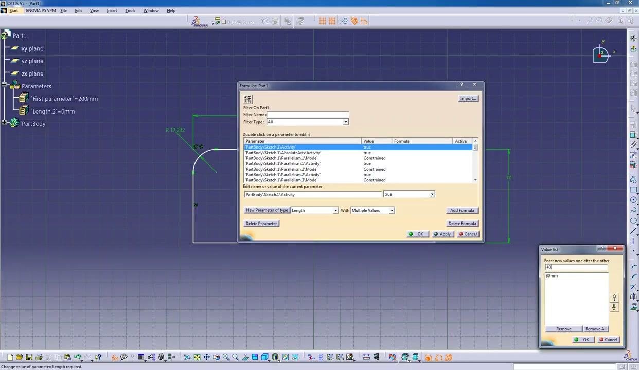
In the Formulas dialog, create another parameter of type Length with Multiple Values. In the Value list dialog, enter these values:
40mm80mm
Click OK to confirm.
Confirm the second parameter
Confirm the creation of the second parameter in the Formulas dialog. The parameter is named Second parameter and is set to 80mm. The Value list dialog shows 80mm and 40mm as possible values. Click OK in the Value list dialog.
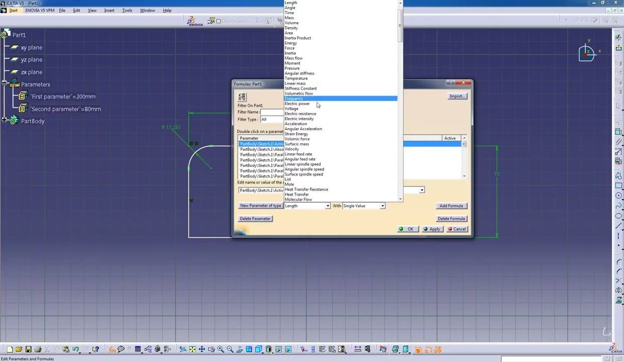
The parameter tree on the left now shows:
First parameter= 200mmSecond parameter= 80mm
Create a parameter of a different type
You can create parameters of many physical types. In the Formulas dialog, click to create a new parameter and open the drop-down menu of parameter types. The list includes Length, Angle, Area, Volume, Density, Force, Pressure, Temperature, Volumetric flow, Electric power, and more. Scroll the list and highlight Volumetric flow to see the range of available types.
Add a radius parameter
A new parameter named Length.3 appears in the parameter tree with a value of 0mm. In the Formulas dialog, rename it to radius and keep its value at 0mm. The parameter tree updates to show radius = 0mm.
Edit the radius value
The Edit Parameter dialog lets you change the value of radius. Enter 10 in the value field so that the parameter reads radius = 10mm, then click OK. The parameter tree shows radius = 10mm, and the sketch displays the rectangle with a rounded corner.
Open the Formula Editor for a sketch dimension
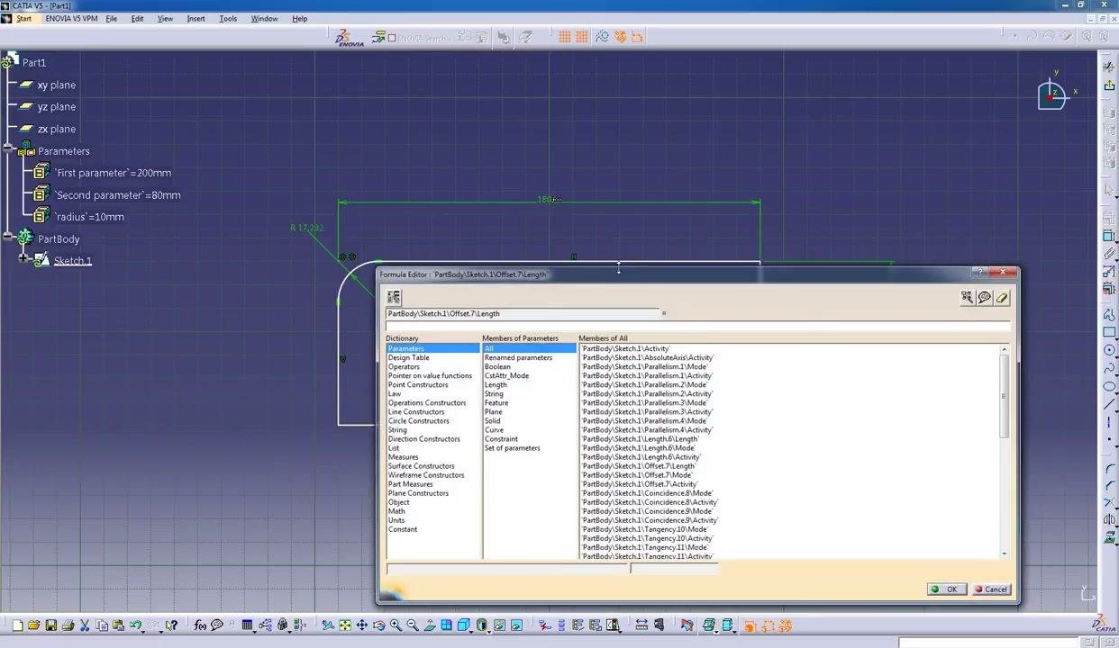
Open the Formula Editor for a sketch dimension, such as PartBody\Sketch.1\Offset.7\Length. The window shows:
- A dictionary of parameter types and constructors on the left.
- Lists of available parameters and members in the center and on the right.
- The formula input field at the top.
The sketch area remains visible in the background.
Select the first parameter in the Formula Editor
In the Formula Editor, select First parameter from the parameter list. The parameter tree highlights First parameter = 200mm. The formula input field is ready to link this parameter to the selected sketch dimension.
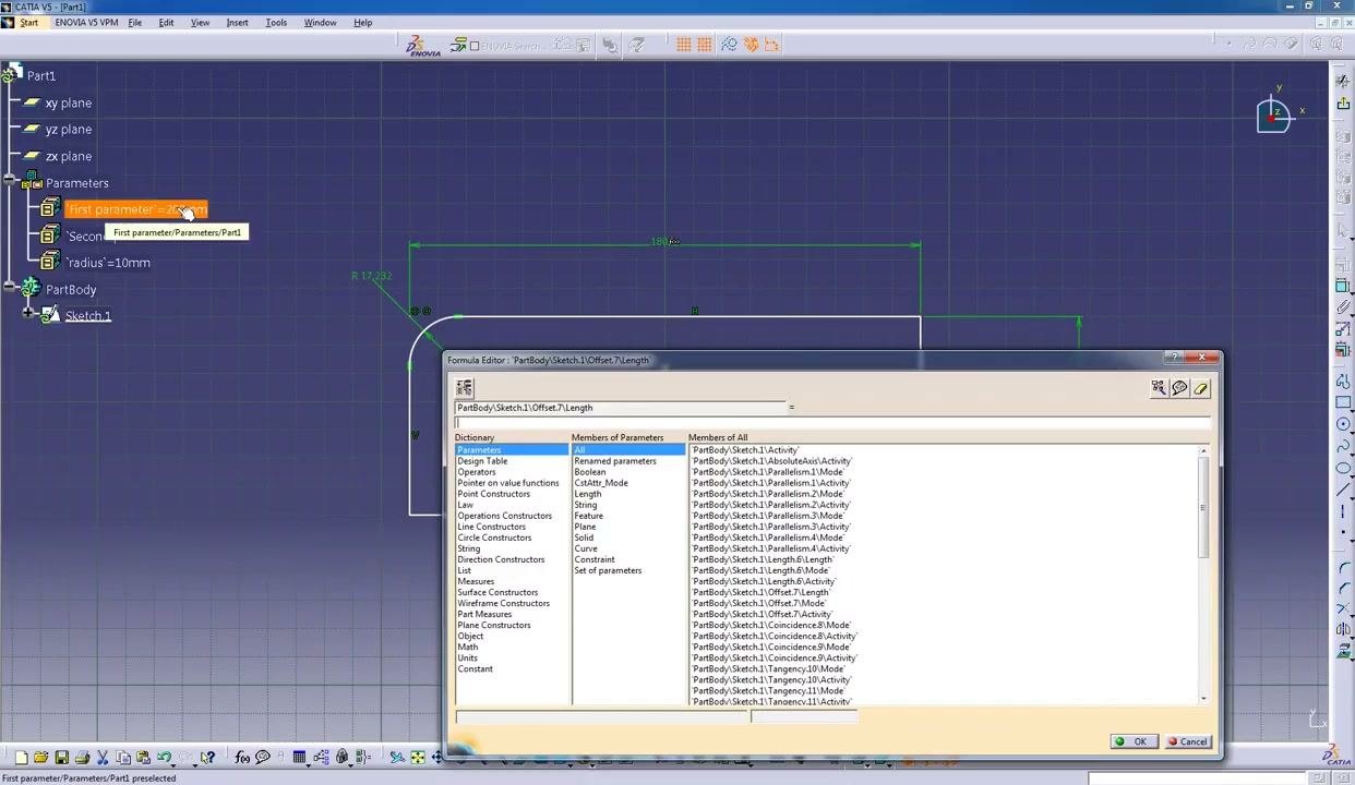
Confirm the automatic update for the first relation
An Automatic update? dialog appears with this message: "This relation is synchronous and contains only parameters. Do you want this relation to be updated anyway when global Update is performed as specified in the options?" Click Yes. The parameter-driven relation now updates automatically.
Link the second parameter to a sketch dimension
Open the Formula Editor for the dimension PartBody\Sketch.1\Length.6\Length. The window shows:
- The formula input field at the top, which displays
Second parameter. - The Dictionary pane on the left, with categories such as Parameters, Design Table, and Operators.
- The center pane, which lists
Renamed parameters, includingSecond parameter. - The right pane, which lists all available members.
In the background, the sketch shows the rectangle with green dimension lines for 200mm and 80mm. The parameter tree shows First parameter = 200mm, Second parameter = 80mm, and radius = 10mm.
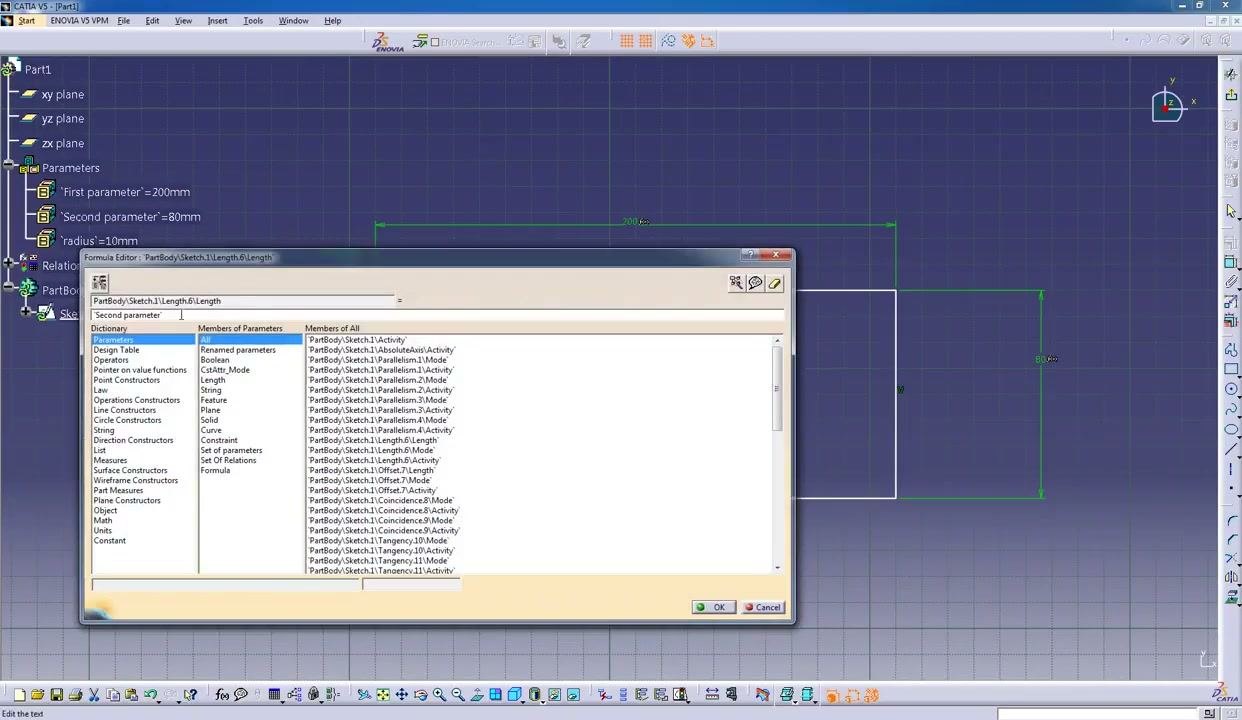
Confirm the automatic update for the second relation
The Automatic update? dialog appears again. Click Yes to confirm automatic updates for this relation. Both parameters now drive their sketch dimensions and update automatically.
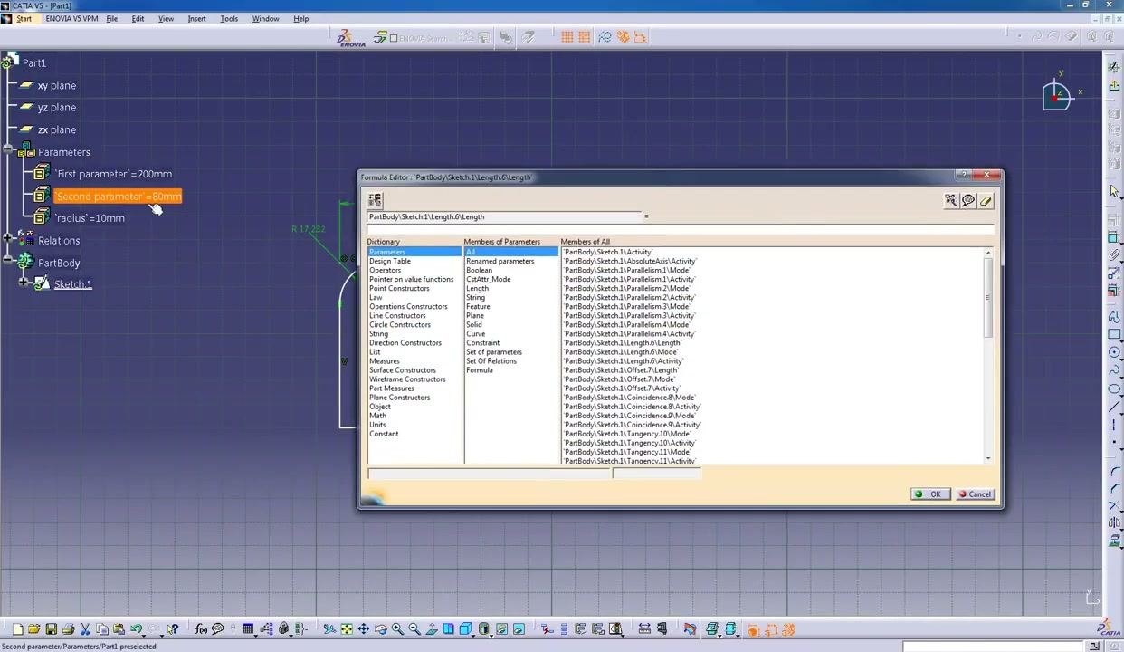
Link the radius parameter to the sketch radius
Open the Formula Editor for the radius dimension PartBody\Sketch.1\Radius.12\Radius. The formula input field at the top displays radius, and the center pane highlights radius under Renamed parameters. The parameter tree highlights radius = 10mm, and the sketch shows the rectangle with a rounded corner. This links the radius parameter to the rounded corner.
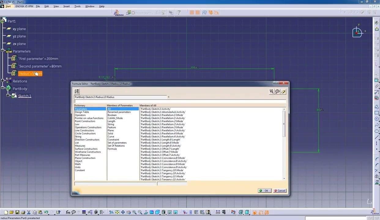
Create a 3D pad from the parameterized sketch
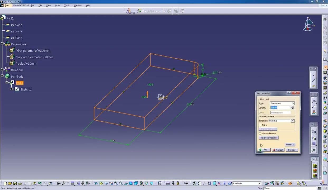
Switch to the 3D view. The Pad Definition dialog appears with these settings:
- First Limit is set to
Type: Dimension. - Length is set to
20mm. - Selection is set to
Sketch.1. - Thick, Reverse Direction, and Mirrored extent are visible but not selected.
The 3D preview shows the extruded pad. The parameter tree shows all parameters and the new Pad.1 feature under PartBody.
Change the first parameter from the drop-down list
Open the Edit Parameter dialog for First parameter. The drop-down menu shows the two values you defined, 200mm and 100mm. Select 100mm. The 3D model updates to the new length, and the parameter tree shows First parameter = 100mm.
Edit the radius parameter
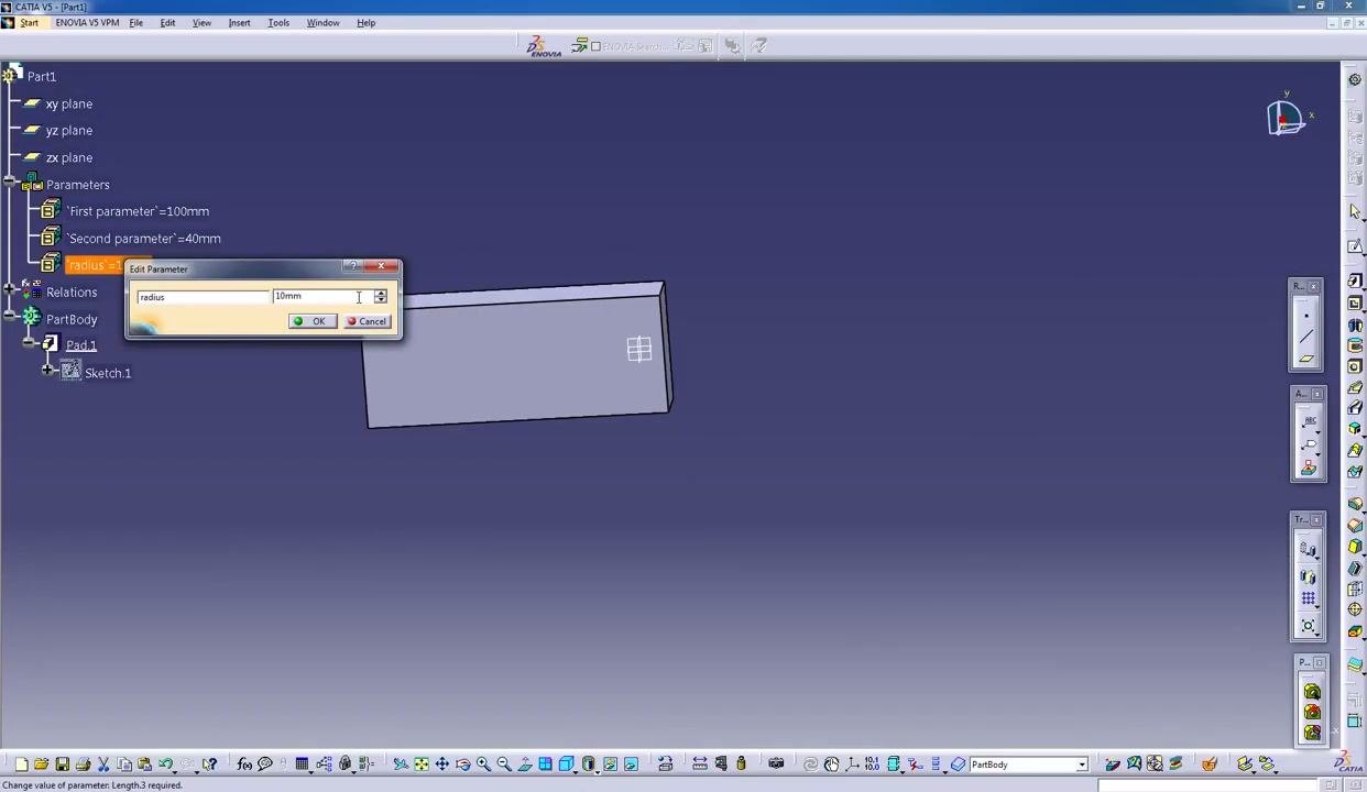
Open the Edit Parameter dialog for radius. The value field displays 10mm. Enter a new value or keep the current one. The 3D model updates to reflect the radius, and the parameter tree shows radius = 10mm.
Confirm the radius value
With the Edit Parameter dialog for radius still open and the value at 10mm, click OK to apply it. The 3D model keeps the current radius, and the parameter tree continues to show radius = 10mm.
Summary
You now know how to create parameters in CATIA V5 and use them in a design. You created length parameters with multiple values and a radius parameter, linked each one to a sketch dimension with the Formula Editor, and confirmed automatic updates. Changing a parameter value in the Edit Parameter dialog now updates the geometry of the parameterized sketch and the 3D pad.
What's next
- Use the Edit Parameter dialog to switch
First parameterorSecond parameterbetween their listed values and watch the pad update. - Create parameters of other types from the parameter type drop-down in the Formulas dialog.
Generation details: cost, quality tiers
Docsie billed 2,500 credits ($1.75) to analyze this 5-minute video at standard quality. The rewrite, template fill and Word/PDF exports were included. The same video at each quality tier:
| Quality | Frames sampled | Credits | Approx. cost |
|---|---|---|---|
| Draft | every 16-30 s | 1,250 | $0.88 |
| Standard (this guide) | every 8-15 s | 2,500 | $1.75 |
| Detailed | every 4-7 s | 5,000 | $3.50 |
| Ultra | every 1-3 s | 10,000 | $7.00 |
Credits priced at $0.70 per 1,000; plans include a monthly allowance. Enterprise customers on on-premise or bring-your-own-model deployments run this on their own inference and pay no per-video credits.
Generated by Docsie Video-to-Docs on 2026-11-15 from a 1-minute video. Screenshots are frames from the source video and belong to their creator, alina, whose original is embedded above. If you own this video and want the guide removed or credited differently, contact us and we will act within one business day.