
How to Create a Plane in CATIA
This guide shows you how to create a plane in CATIA V5 in the Part Design workspace. You start a new part, open the Plane Definition dialog, and choose a plane type. The types covered are offset, parallel through point, angle/normal, through three points, through two lines, through point and line, through planar curve, normal to curve, and tangent to surface. Each type uses different references, so you can position a plane precisely on your model.
Video: How to create planes in CATIA v5 by Vishal Sonawane (2017). All credit for the demonstration goes to the creator; watch the original on YouTube. The written guide below was generated from this video by Docsie. Creator? Request a change or removal.
This guide shows you how to create a plane in CATIA V5 in the Part Design workspace. You start a new part, open the Plane Definition dialog, and choose a plane type. The types covered are offset, parallel through point, angle/normal, through three points, through two lines, through point and line, through planar curve, normal to curve, and tangent to surface. Each type uses different references, so you can position a plane precisely on your model.
Prerequisites
- CATIA V5 installed on your computer, with its icon on the desktop.
- For the point, line, curve, and surface plane types, a part with geometry to reference (for example,
Pad.1vertices and edges).
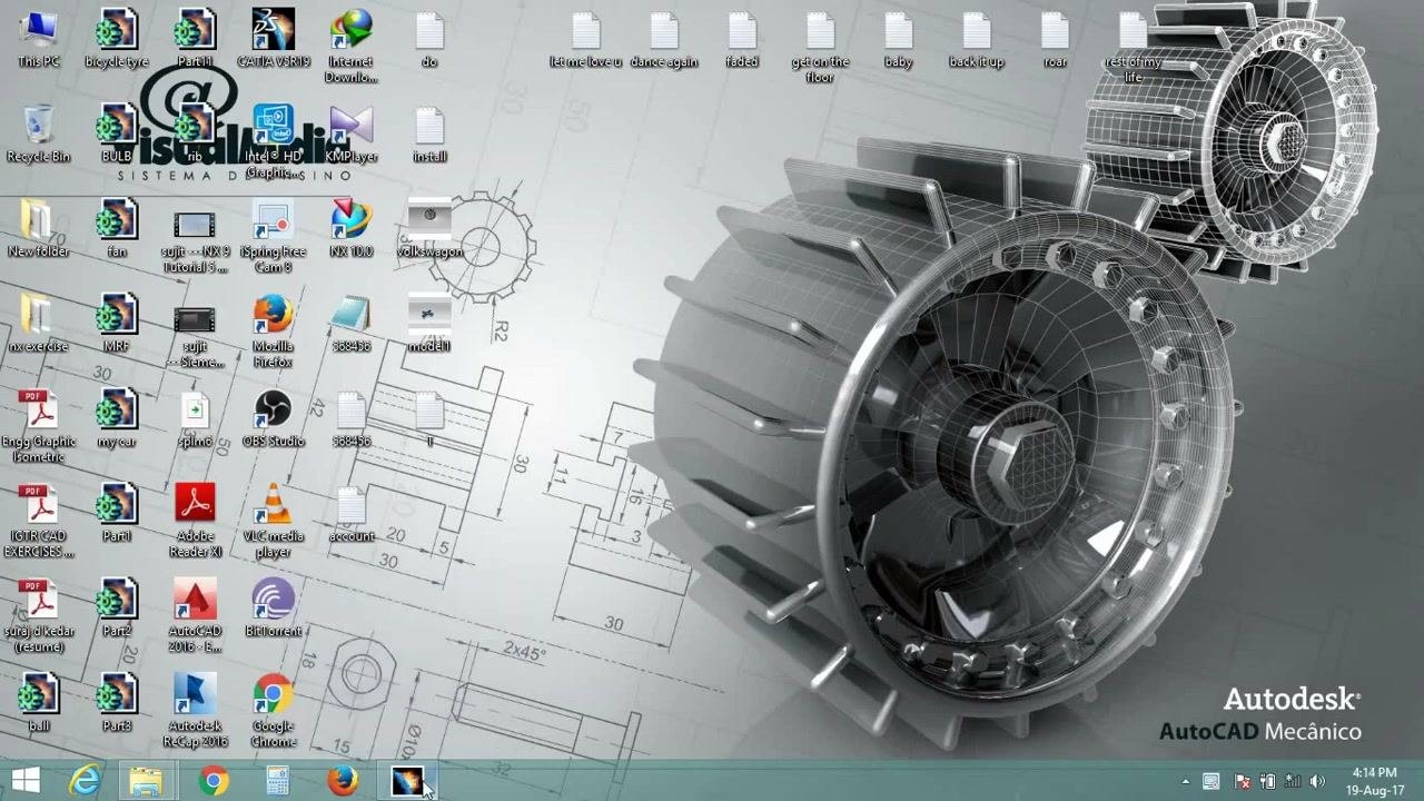
Open CATIA V5
- Make sure your computer is on the desktop.
- Double-click the CATIA V5 icon to launch the application.
Start a new part in Part Design
- In the top menu of CATIA V5, click Start.
- Hover over Mechanical Design.
- Select Part Design from the dropdown.
The Part Design workspace displays the default planes (xy plane, yz plane, and zx plane) and a PartBody. If you need basic geometry to reference, use the sketch tools to create it.
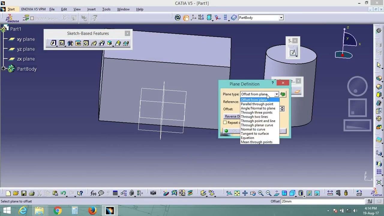
Create a plane in CATIA with an offset from a plane
- In the Part Design workspace, select the Plane tool.
- In the Plane Definition dialog, set Plane type to Offset from plane.
- For Reference, select the base plane you want, for example
xy plane. - Enter the offset value in the Offset field, for example
20mmor100mm. - Click OK.
Create a plane parallel through a point
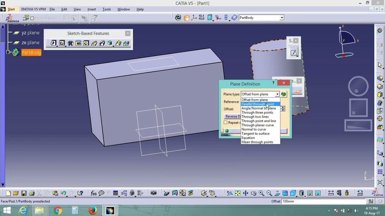
- Open the Plane Definition dialog again.
- Set Plane type to Parallel through point.
- For Reference, select the plane you want, for example
yz plane. - For Point, select a vertex or point on your model, for example
Pad.1\Vertex. - Click OK.
CATIA creates a plane parallel to the reference plane that passes through the selected point.
Create a plane at an angle to a reference plane
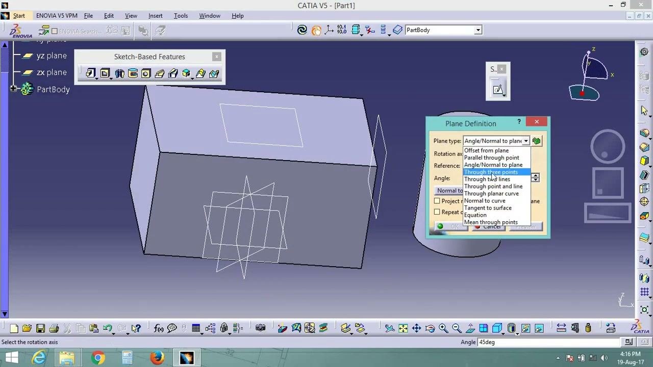
- In the Plane Definition dialog, set Plane type to Angle/Normal to plane.
- For Rotation axis, select Z Axis from the dropdown menu.
- For Reference, select
zx plane. - In the Angle field, enter
45deg. - Click OK.
Create a plane through three points
- Open the Plane Definition dialog.
- Set Plane type to Through three points.
- For Point 1, select
Pad.1\Vertex. - For Point 2, select another
Pad.1\Vertex. - For Point 3, select a third
Pad.1\Vertex. - Click OK.
CATIA creates a plane that passes through the three selected points.
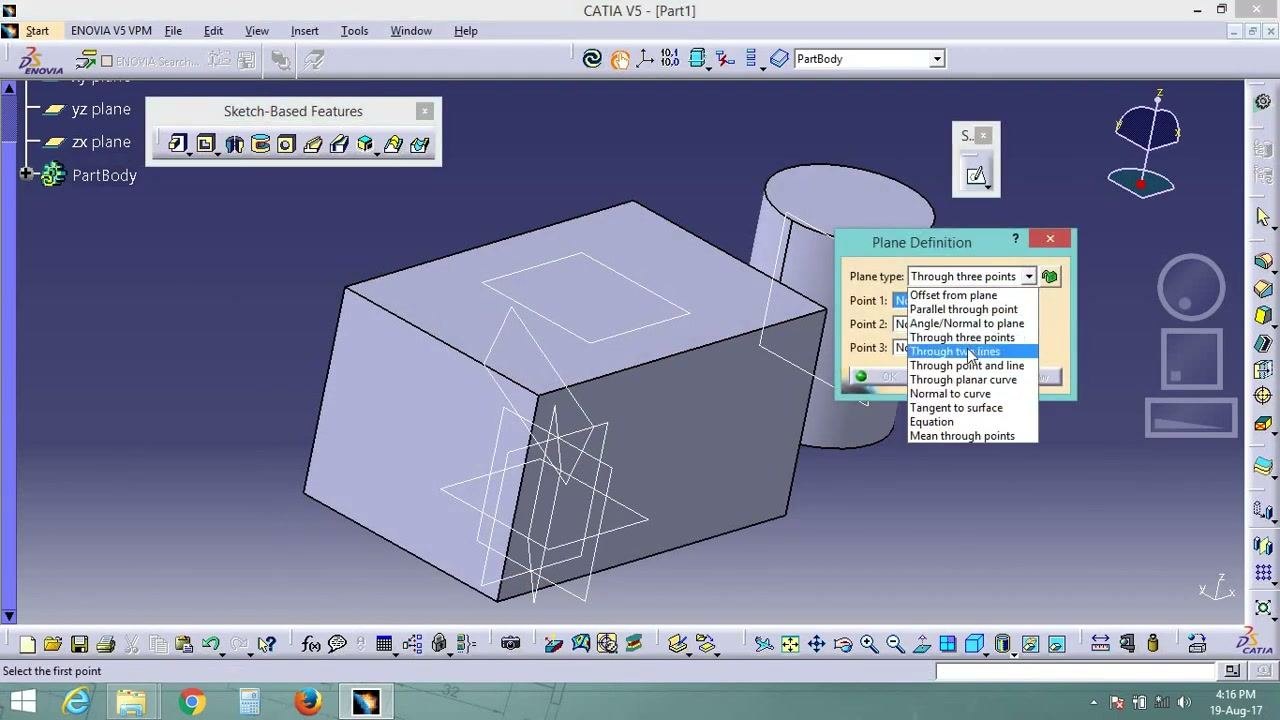
Create a plane through two lines
- Open the Plane Definition dialog.
- Set Plane type to Through two lines.
- For Line 1, select
Pad.1\Edge. - For Line 2, select another edge or line as required.
- (Optional) Select Forbid non coplanar lines to restrict the selection to coplanar lines only.
- Click OK.
Create a plane through a point and a line
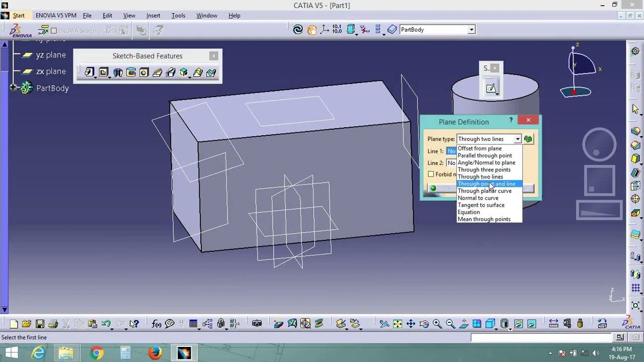
- Open the Plane Definition dialog.
- Set Plane type to Through point and line.
- For Point, select
Pad.1\Vertex. - For Line, select
Pad.1\Edge. - Click OK.
CATIA creates a plane that passes through the selected point and line.
Create a plane through a planar curve
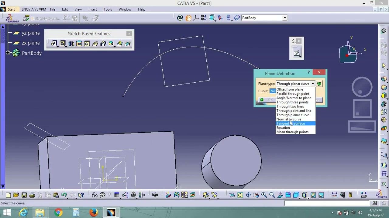
You can also create a plane in CATIA from curves and surfaces, starting with a planar curve.
- Open the Plane Definition dialog.
- Set Plane type to Through planar curve.
- For Curve, select the planar curve from your model.
- Click OK.
Create a plane normal to a curve
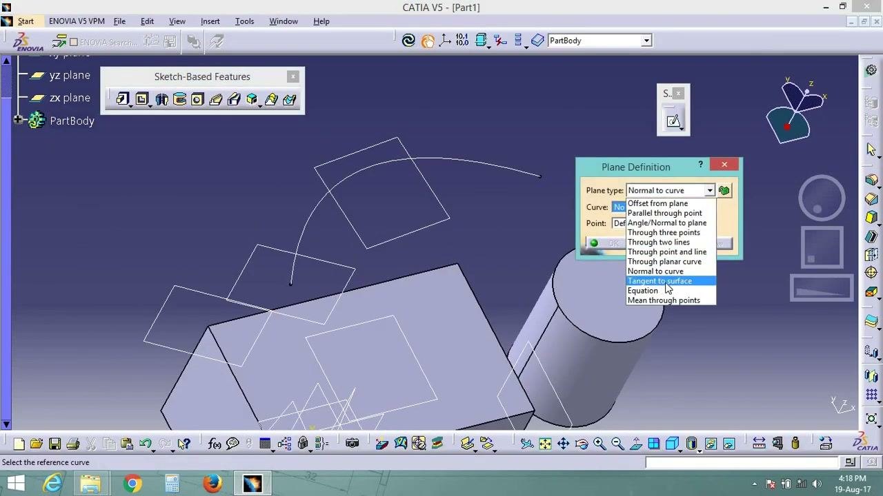
- In the Plane Definition dialog, set Plane type to Normal to curve.
- For Curve, select the curve from your model.
- For Point, select the point on the curve where the plane should be normal.
- Click OK.
Create a plane tangent to a surface
- In the Plane Definition dialog, set Plane type to Tangent to surface.
- For Surface, select the surface from your model.
- For Point, select or create the point on the surface where the plane should be tangent.
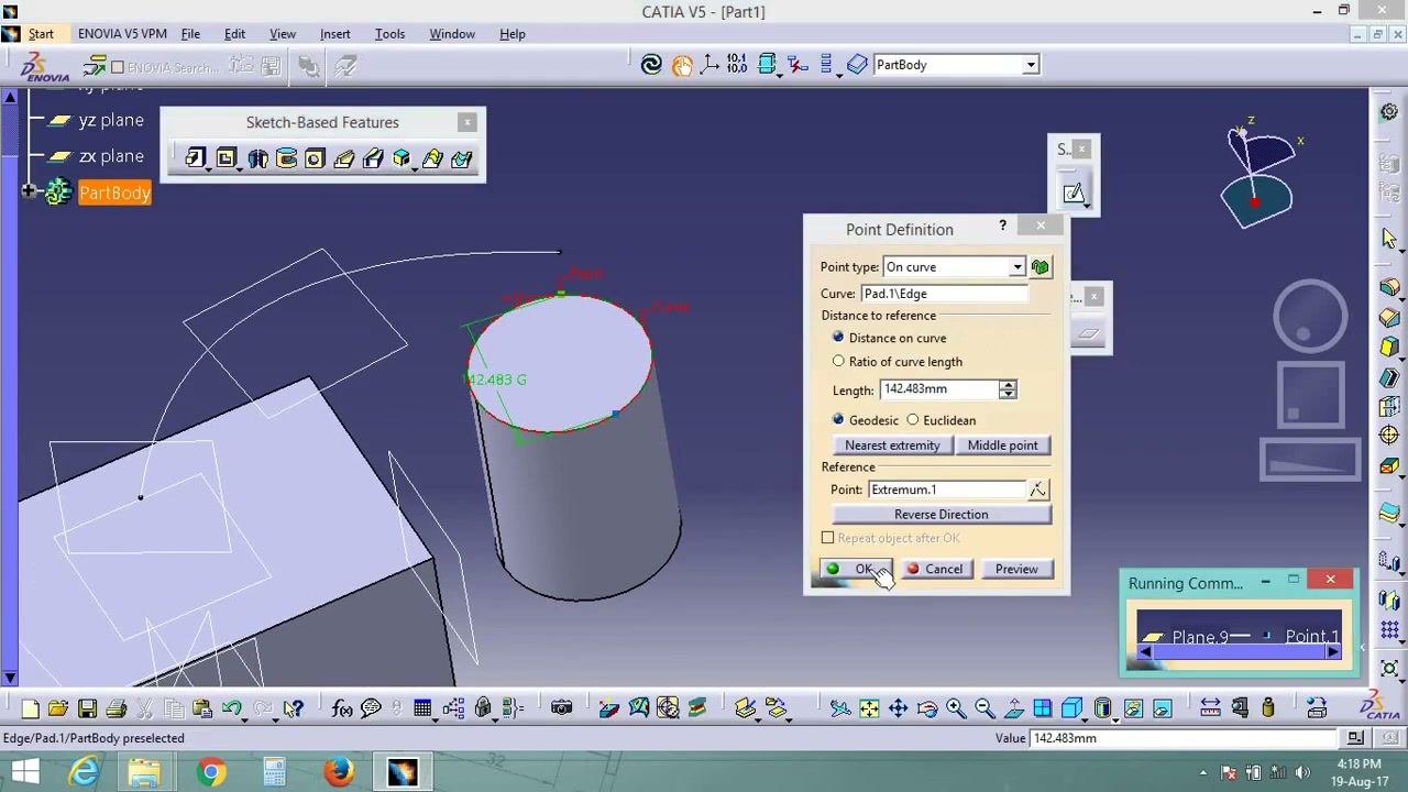
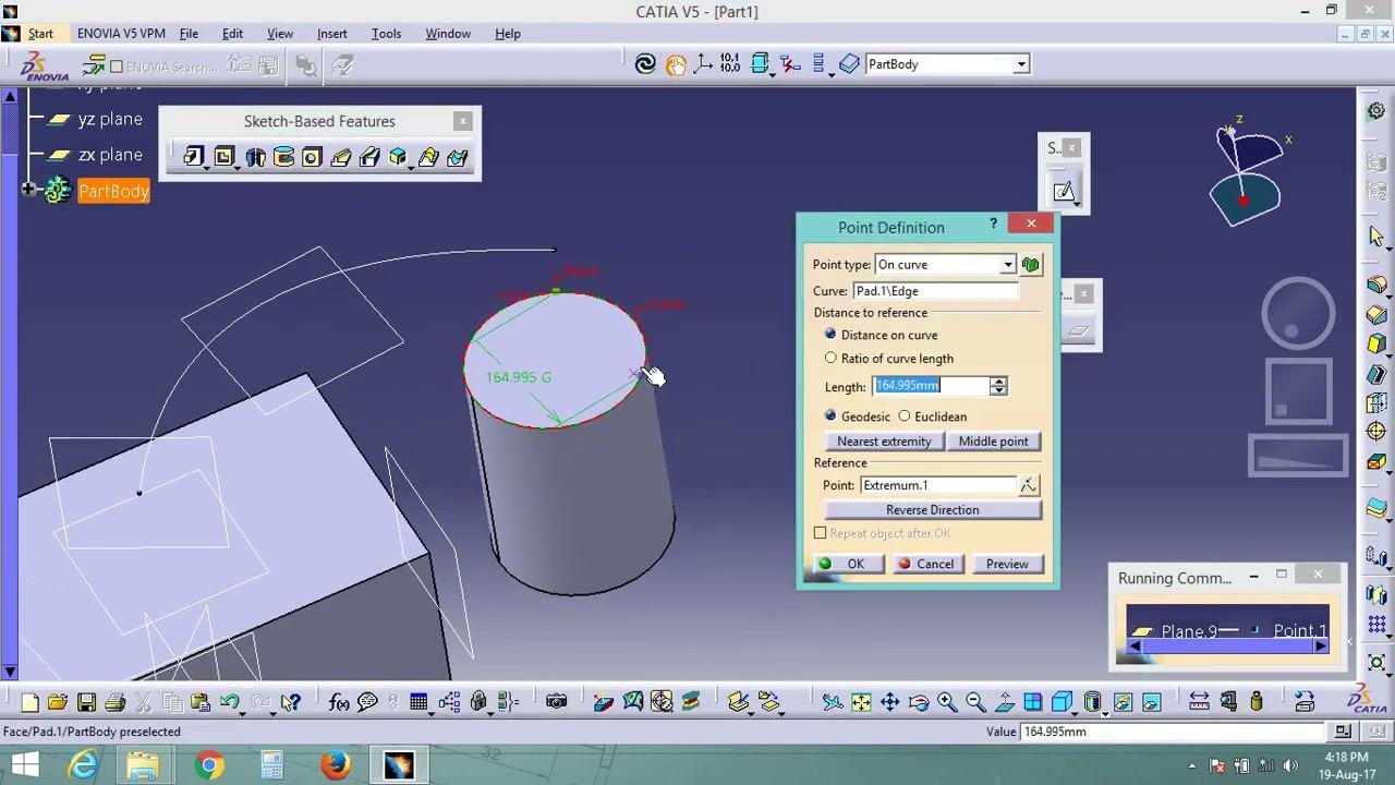
If a point does not exist yet, right-click in the Point field and choose to create a new point. Then complete the Point Definition dialog:
- Set Point type to On curve.
- For Curve, select the edge or curve on the surface, for example
Pad.1\Edge. - Set Distance to reference as needed, for example
Length = 142.483mm. - Choose Nearest extremity or Middle point as the reference.
- Click OK to create the point.
Finally, click OK in the Plane Definition dialog to create the tangent plane.
Review the planes you created
- Review the workspace and confirm that the new planes (through planar curve, normal to curve, and tangent to surface) are visible and correctly positioned relative to your model.
- Close any open dialogs you no longer need, such as Reference or Point Definition.
Summary
You now know how to create a plane in CATIA V5 using offsets, points, lines, angles, curves, and surfaces. These reference planes support precise modeling of complex geometries.
What's next
- Save your work.
- Review each plane for accuracy before you continue with further modeling operations.
Generation details: cost, quality tiers
Docsie billed 2,500 credits ($1.75) to analyze this 5-minute video at standard quality. The rewrite, template fill and Word/PDF exports were included. The same video at each quality tier:
| Quality | Frames sampled | Credits | Approx. cost |
|---|---|---|---|
| Draft | every 16-30 s | 1,250 | $0.88 |
| Standard (this guide) | every 8-15 s | 2,500 | $1.75 |
| Detailed | every 4-7 s | 5,000 | $3.50 |
| Ultra | every 1-3 s | 10,000 | $7.00 |
Credits priced at $0.70 per 1,000; plans include a monthly allowance. Enterprise customers on on-premise or bring-your-own-model deployments run this on their own inference and pay no per-video credits.
Generated by Docsie Video-to-Docs on 2026-11-15 from a 4-minute video. Screenshots are frames from the source video and belong to their creator, Vishal Sonawane, whose original is embedded above. If you own this video and want the guide removed or credited differently, contact us and we will act within one business day.