
How to Create a 2D Drawing in CATIA
This guide shows you how to create a 2D drawing in CATIA V5. You start with a blank drawing sheet and insert a front view of your part. Then you add section and auxiliary views, dimension every view, apply hatching, and adjust the isometric view properties.
Video: CATIA V5 Drafting Beginner Tutorial - How to create a 2D using Drafting by Catia V5-V6 Tutorials (2015). All credit for the demonstration goes to the creator; watch the original on YouTube. The written guide below was generated from this video by Docsie. Creator? Request a change or removal.
This guide shows you how to create a 2D drawing in CATIA V5. You start with a blank drawing sheet and insert a front view of your part. Then you add section and auxiliary views, dimension every view, apply hatching, and adjust the isometric view properties.
Prerequisites
- CATIA V5 with access to the Drawing workbench.
- A part to insert into the drawing sheet as a front view.
Set up the drawing sheet and front view
Step 1: Open a new drawing sheet to start your 2D drawing
Launch CATIA V5 and open a new drawing document. The workspace shows a blank drawing sheet labeled "PLANCHE1" with a thick border.
The left panel shows the drawing structure: Drawing1 > PLANCHE1. Toolbars appear at the top, left, and right of the CATIA V5 Drawing workbench.
Step 2: Insert the front view of the part
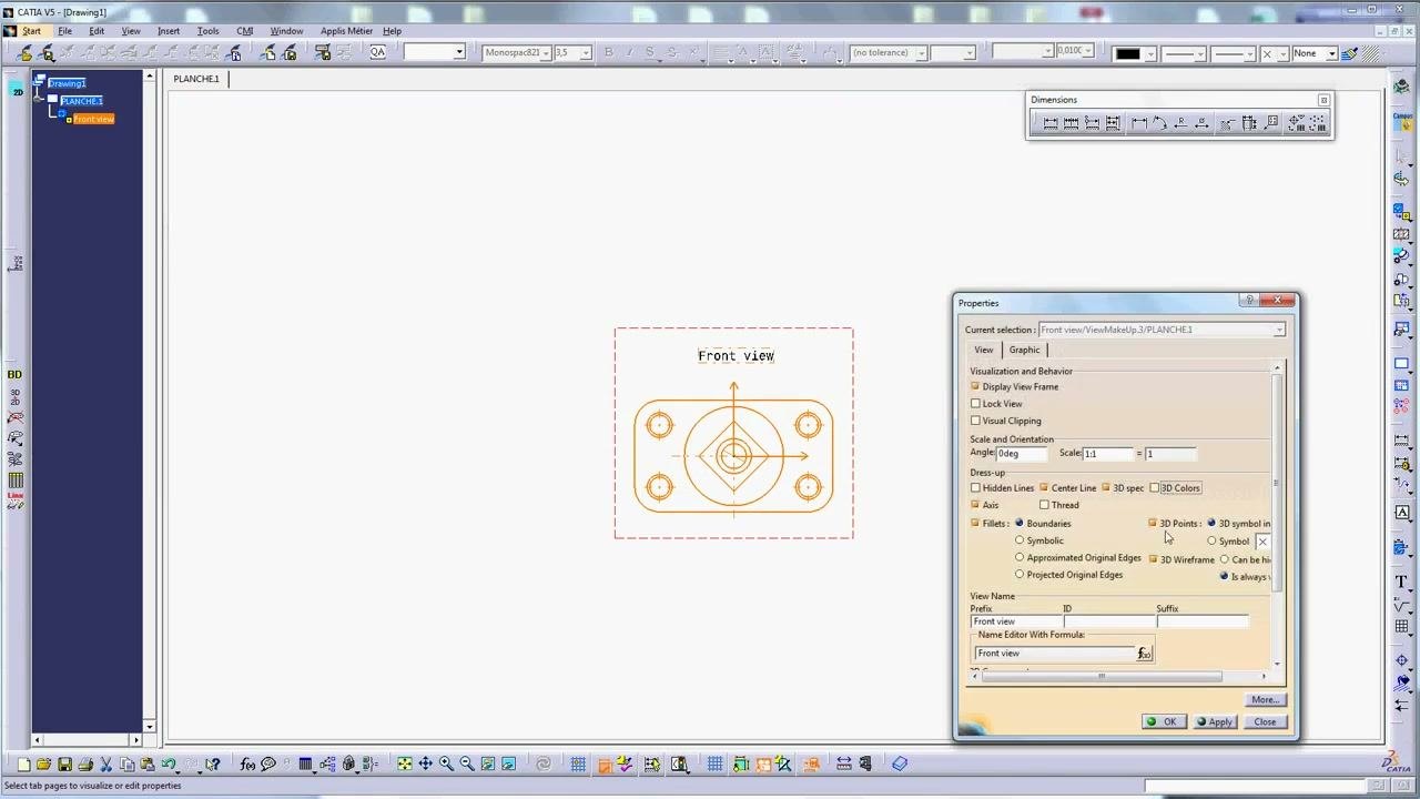
Insert a front view of the part into the drawing sheet. The view appears centered on the sheet, outlined in orange, with its axes and the label "Front view" below the drawing.
The left panel now shows Drawing1 > PLANCHE1 > Front view. A progress bar appears at the bottom right while the view is inserted.
Step 3: Open the view properties and apply your changes
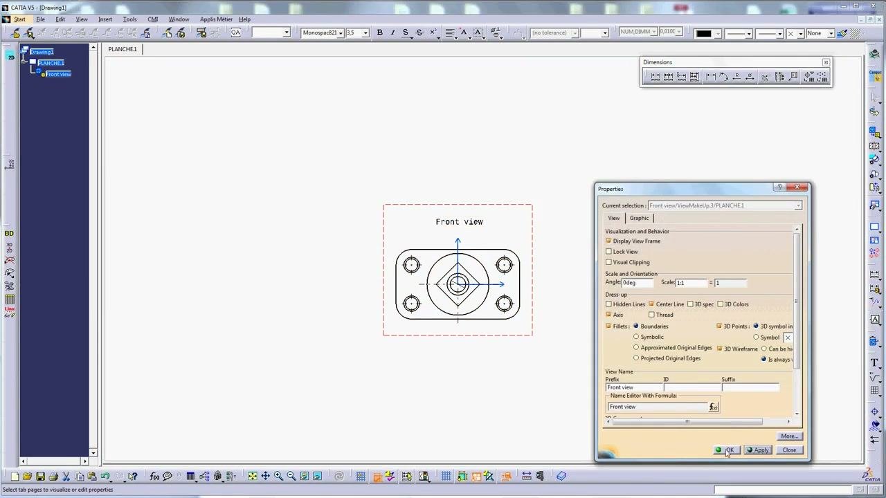
Right-click or double-click the "Front view" to open the Properties dialog. The window appears on the right with options for visualization, scale, orientation, and dress-up features.
In this example, the scale is 1:1 and the angle is 0 degrees. Options for hidden lines, axes, threads, fillets, and 3D points are available. The view name is editable and set to "Front view".
Click OK or Apply to confirm your changes. The front view updates and is now drawn in black lines. The Properties dialog stays open if you need further adjustments.
Add section and auxiliary views
Step 4: Add section view A-A and dimension lines
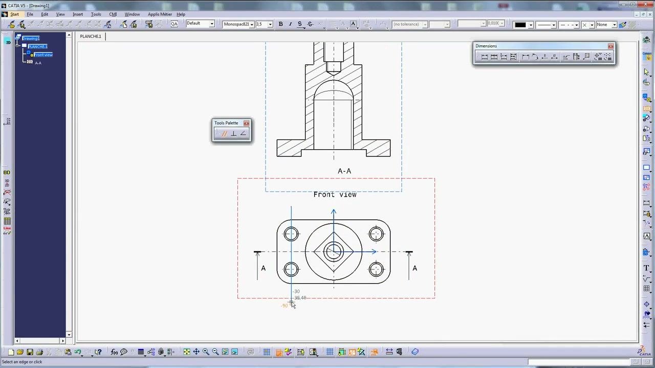
Insert a section view labeled "A-A" above the front view. It shows an internal cross-section of the part. Add dimension lines and labels such as "A-A" and "B-B" to the front view.
The Tools Palette window appears, which shows that the dimensioning or sectioning tools are active. The drawing now contains section view "A-A" at the top and the front view in the center. Dimension lines and section indicators (arrows and labels) are also visible.
Step 5: Insert section view B-B
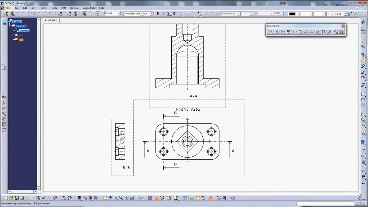
Add a second section view labeled "B-B" to the left of the front view. The drawing now shows section view A-A at the top, B-B on the left, and the front view in the center. Dashed boxes with labels enclose all the views.
The left panel updates to show the new section view in the drawing tree.
Step 6: Add an auxiliary view
Insert an auxiliary view labeled "Auxiliary view C" to the right of the front view. It shows a different projection of the part, with a basic outline and dimensions.
The left panel now lists all views: Front view, A-A, B-B, and Auxiliary view C. The sheet contains A-A (top), B-B (left), the front view (center), and Auxiliary view C (right).
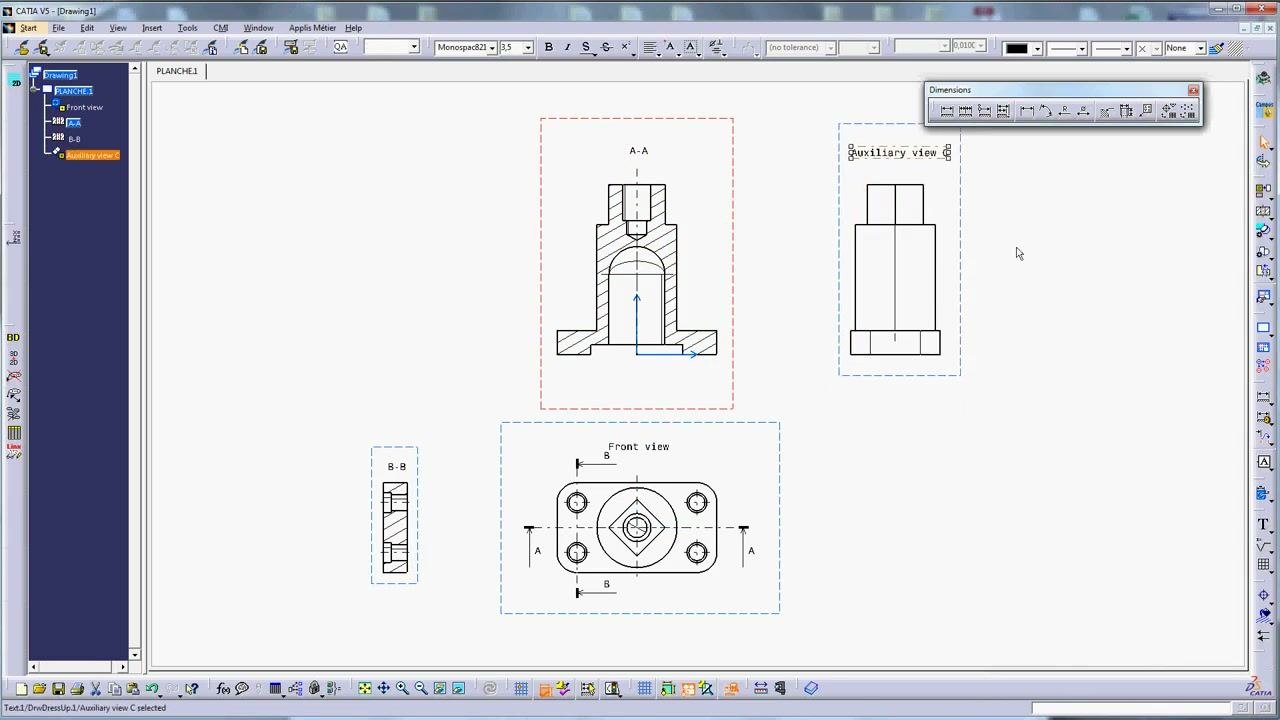
Step 7: Dimension the auxiliary view
Use the Tools Palette to add dimensions to the auxiliary view. Dimension lines and values, for example 12, 65, and 85, appear on the auxiliary view.
The Tools Palette window is visible near the section view, which shows that dimensioning is active. The drawing now includes dimensioning for all views.
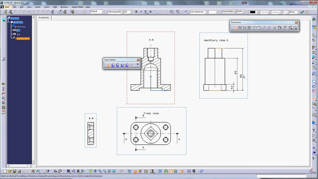
Dimension section view A-A
Step 8: Start dimensioning section view A-A
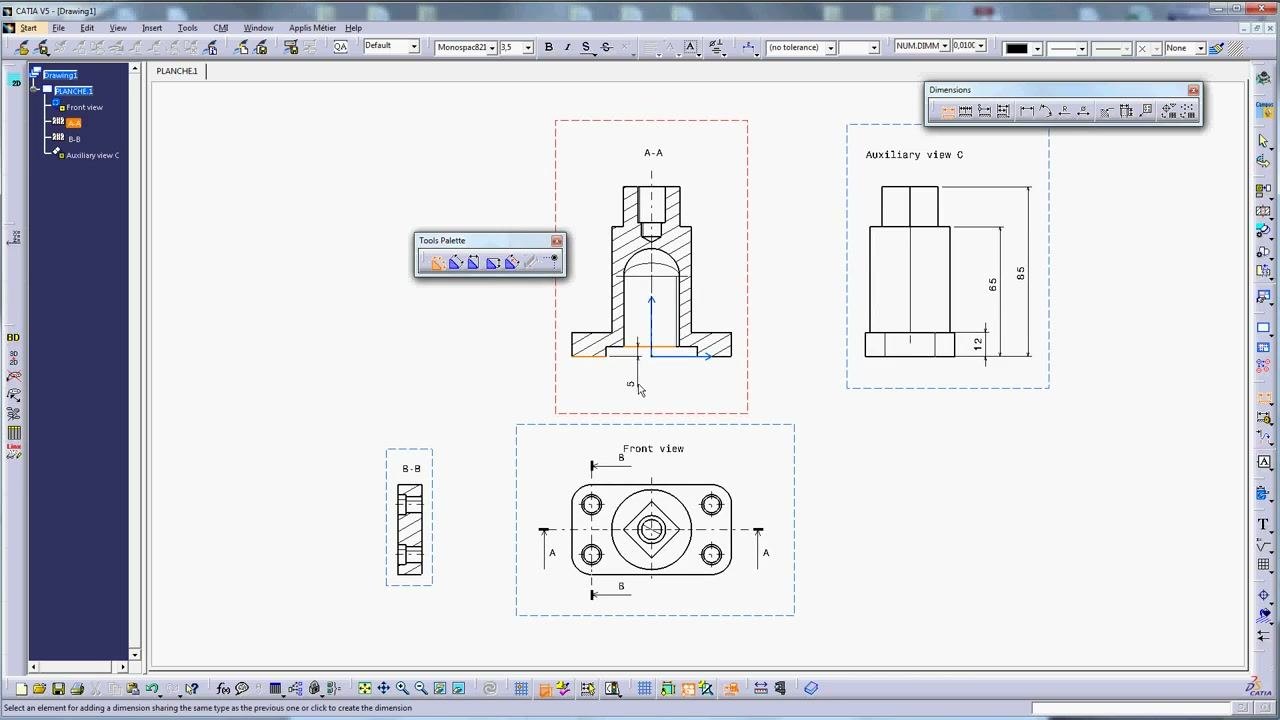
Make sure the Tools Palette and Dimensions toolbars are open and visible. Select section view "A-A", which sits at the top center of the sheet and is outlined in red.
Use the dimensioning tool to add a horizontal dimension at the base of the view. The value "5" appears at the base and indicates the thickness of the lower section.
Step 9: Zoom in and add vertical dimensions
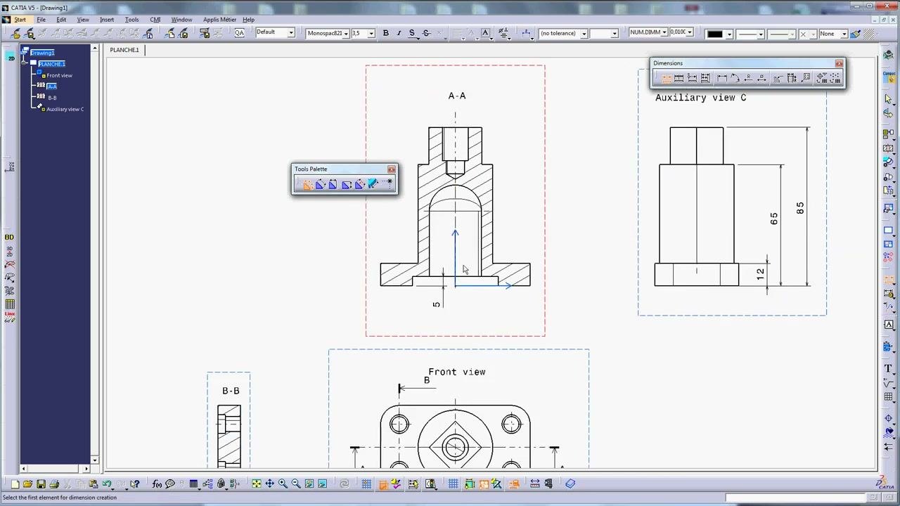
Zoom in on section view "A-A" for precise dimensioning. Add two vertical dimensions on the right side of the view:
- "18" for the upper segment
- "25" for the total height of the upper section
The Tools Palette and Dimensions toolbar stay visible for quick access.
Step 10: Annotate the spherical radius
Add a radius annotation to the curved section of the cross-section. The annotation "R14 Sferic" indicates a spherical radius of 14. It appears with an orange leader line pointing to the arc.
The annotation is in edit mode and highlighted in orange, so you can still place or adjust it.
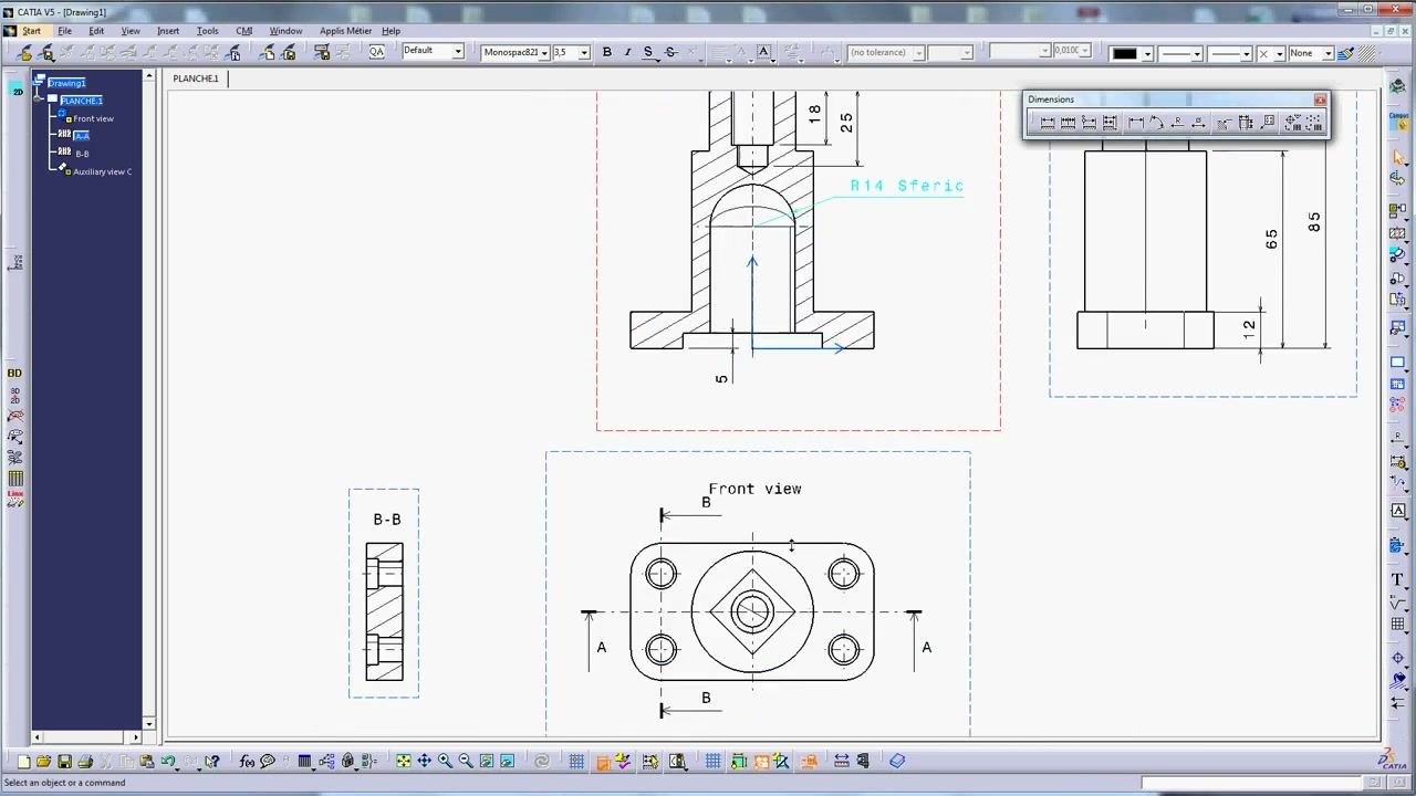
Confirm and place the "R14 Sferic" annotation. It turns blue, which indicates it is finalized. The earlier dimensions ("5", "18", and "25") remain visible, and the sheet shows all views with their updated annotations.
Step 11: Add horizontal dimensions to section view A-A
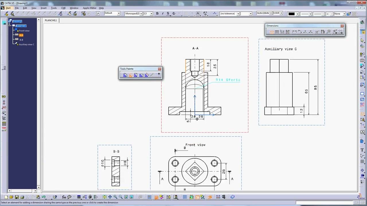
Use the dimensioning tool to add two horizontal dimensions at the base of section view A-A. Both are labeled "28", which indicates symmetrical features.
The Tools Palette is active and the section view is outlined in red. All previously placed dimensions and annotations remain visible.
Step 12: Add a diameter dimension to section view A-A
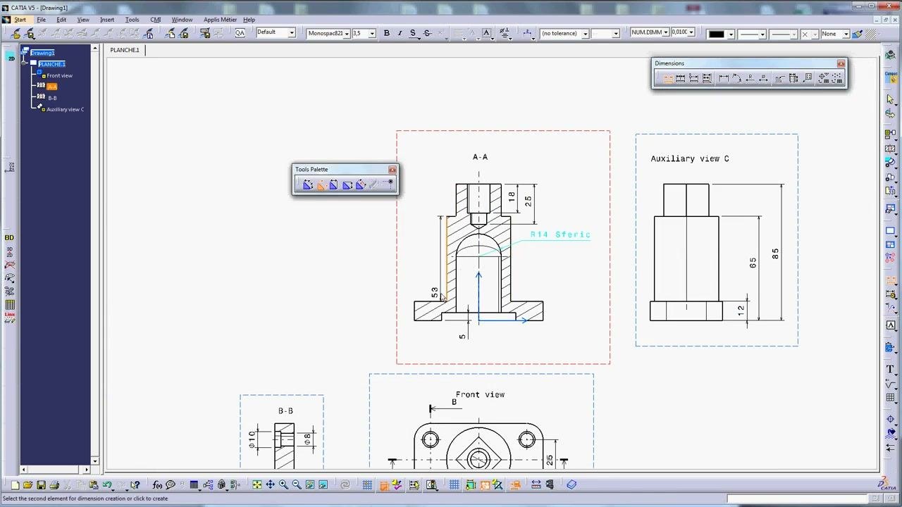
Place a diameter dimension at the base of section view A-A. The dimension "⌀40" indicates the diameter of the lower section.
The Tools Palette remains open for quick tool selection. All other dimensions and the "R14 Sferic" annotation are still visible.
Dimension section view B-B
Step 13: Add diameter dimensions to section view B-B
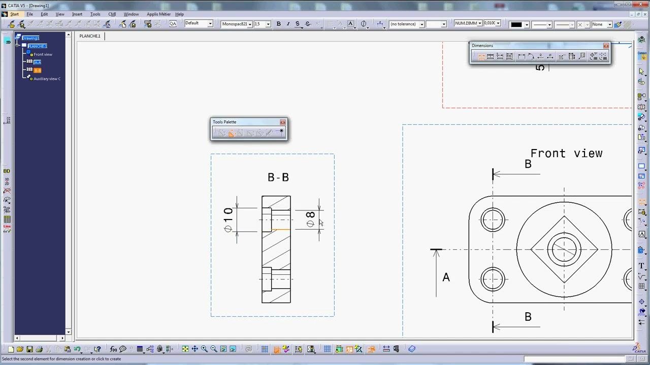
Move to section view "B-B", which is at the bottom left of the sheet and outlined in blue. Use the dimensioning tool to add two horizontal diameter dimensions:
- "10" on the left side
- "8" on the right side
The Tools Palette is active and the cursor is positioned to place or adjust the dimension.
Dimension the front view
Step 14: Add the key dimension to the front view
Use the dimensioning tool to add a key horizontal dimension to the front view. The dimension "60" is placed at the bottom and indicates the overall width between the centers of the outer holes.
The front view is outlined in red, which shows it is the current focus. The Tools Palette is active, and the section indicators "A" and "B" remain visible.
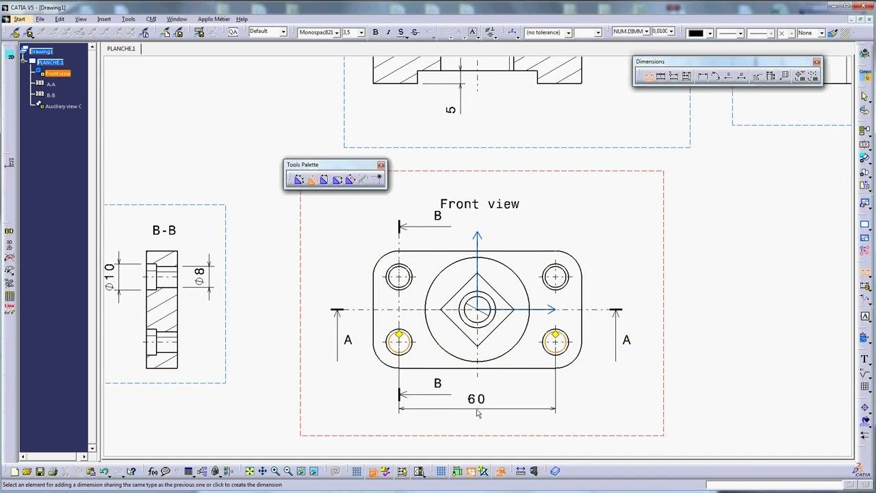
Step 15: Zoom in on the front view
Zoom in on the front view for precise placement of additional dimensions. The Tools Palette is positioned near the center of the front view.
The cursor is active and ready to select elements for dimensioning. The "⌀40" dimension from section view A-A is visible at the top of the workspace.
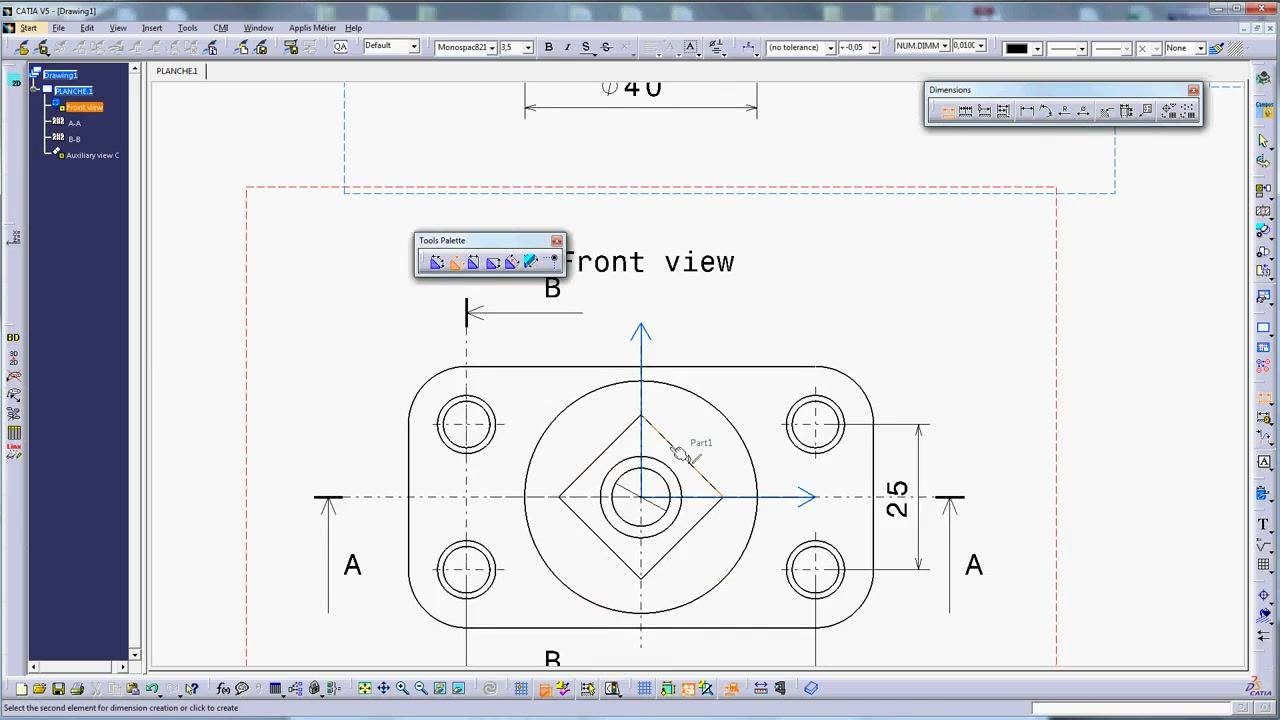
Step 16: Add diameter dimensions to the front view
Use the dimensioning tool to add two diameter dimensions to the front view. Both are labeled "20" and indicate the diameter of the inner and outer circles.
The Tools Palette is active and the dimensions are placed symmetrically.
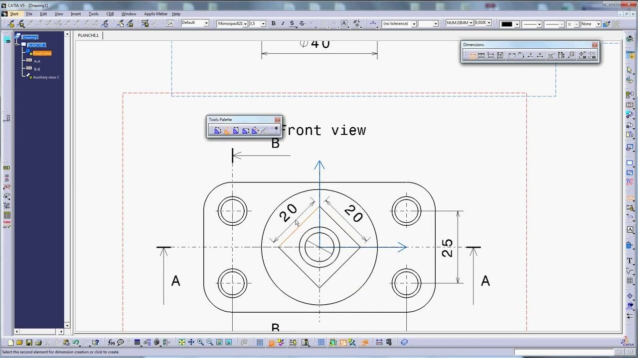
Step 17: Add a radius dimension to the front view
Place a radius dimension labeled "R7" on the inner square feature of the front view. The dimension sits inside the square and clearly indicates the radius.
The previously placed dimensions ("60", "25", "20", and "20") remain visible.
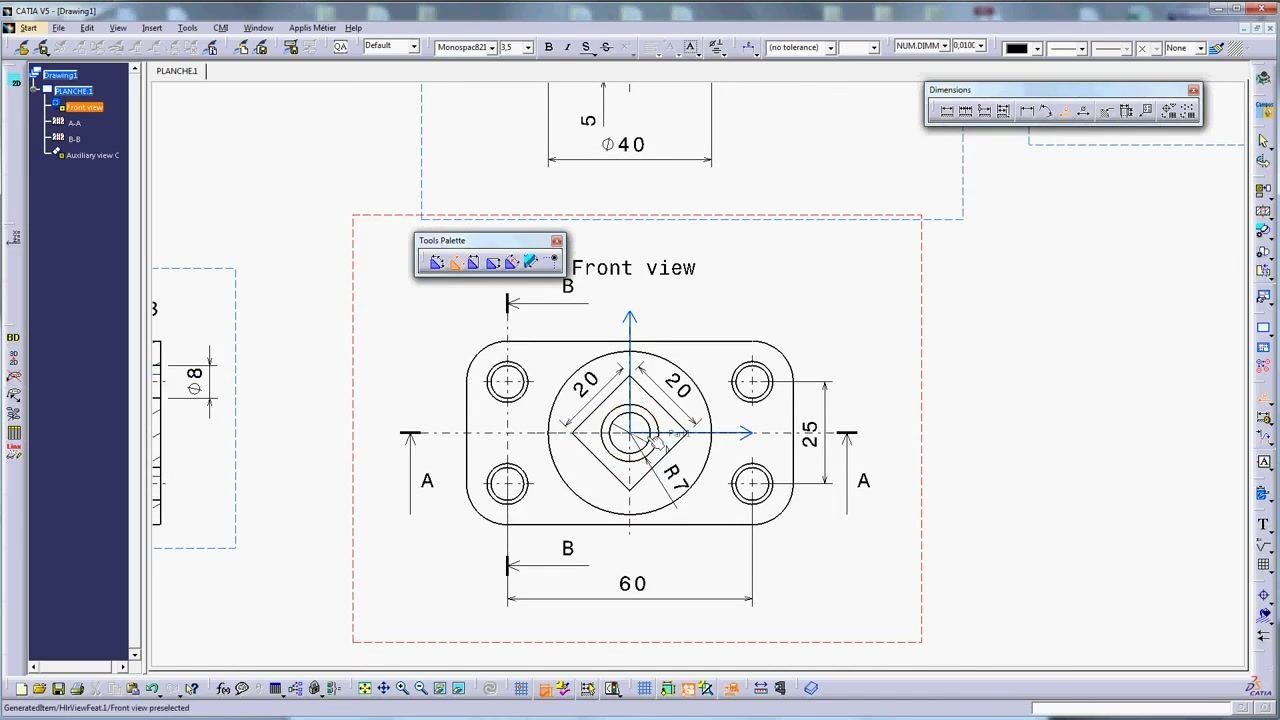
Step 18: Adjust the dimension placement
Adjust the placement of the newly added dimensions for clarity and readability. The Tools Palette remains open for further adjustments.
The drawing now displays all key dimensions and annotations.
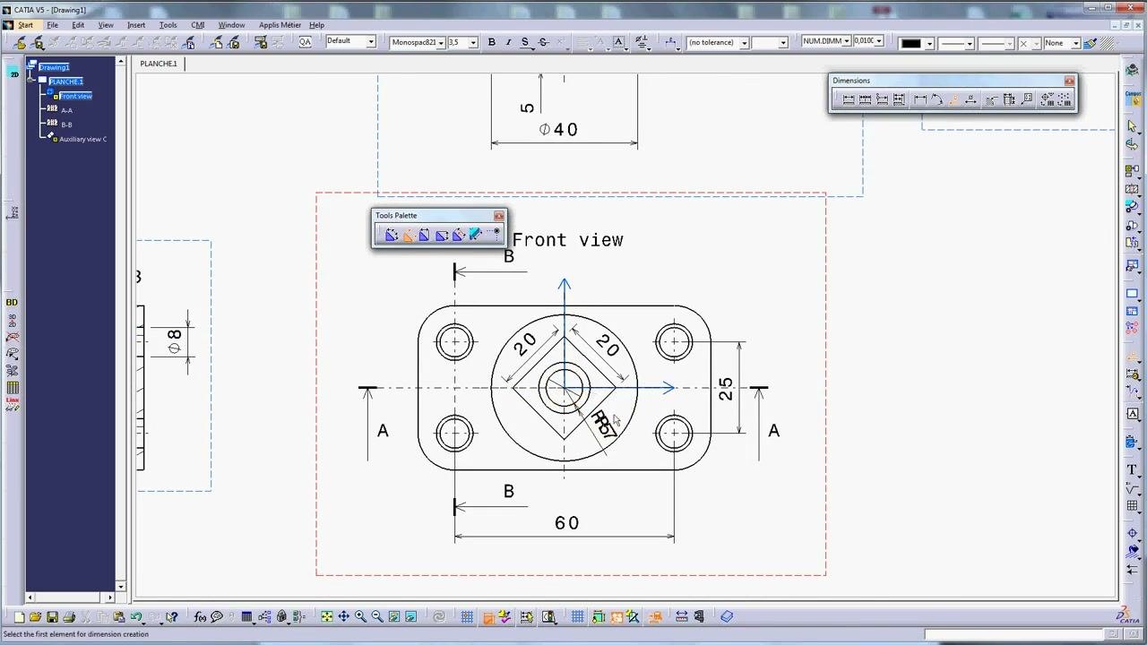
Step 19: Open the dimension properties
Select the newly added dimensions to access their properties. Dimension handles and property options appear, so you can customize items such as line representation and tolerance.
All toolbars and palettes stay accessible for a final review.
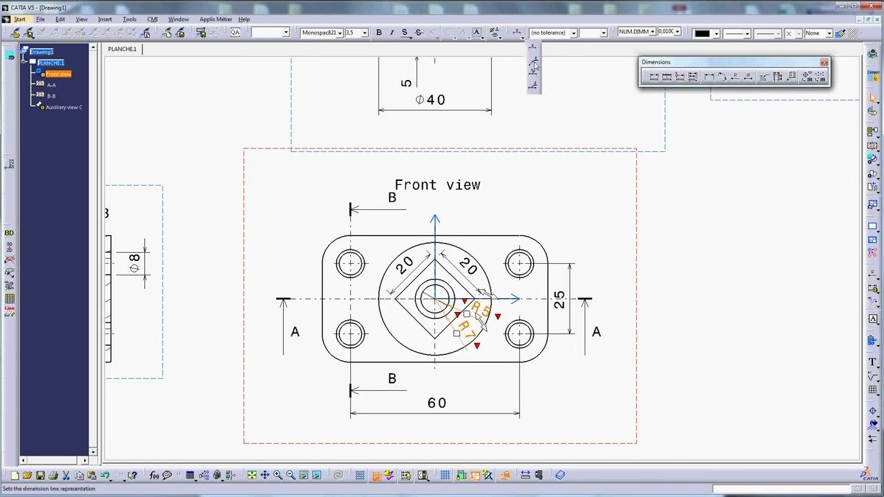
When you finish, the front view shows all of its dimensions clearly placed, and the drawing is ready for review.
Add dimensions and hatching to section views
Step 20: Activate the Tools Palette
Open or activate the floating Tools Palette window. It contains icons for drawing and editing features such as lines, circles, and hatching. Position the palette where you can reach it easily while you work.
Step 21: Add or edit section view dimensions
Select a section view, for example A-A, by clicking inside its dashed blue boundary. Use the Dimensions toolbar to add or modify dimensions. For example, add a diameter dimension (Ø28) or a length dimension (35).
Watch the cursor and the selection highlights as you place or edit the dimension. Confirm that the dimension appears in the correct location on the section view.
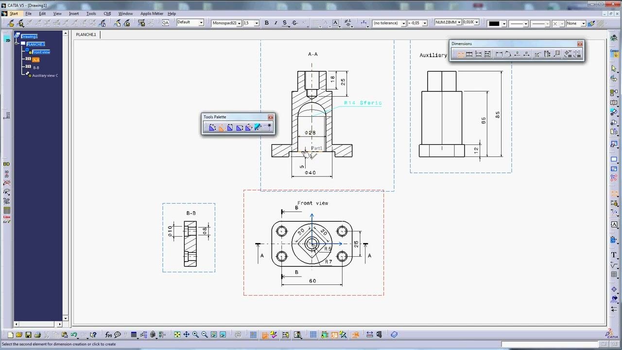
Step 22: Continue dimensioning the section views
Add more dimensions as needed, such as the vertical height (35) on section A-A. Make sure every critical feature is dimensioned for manufacturing or inspection.
Use the Dimensions toolbar to select the appropriate dimension type, such as linear, diameter, or radius.
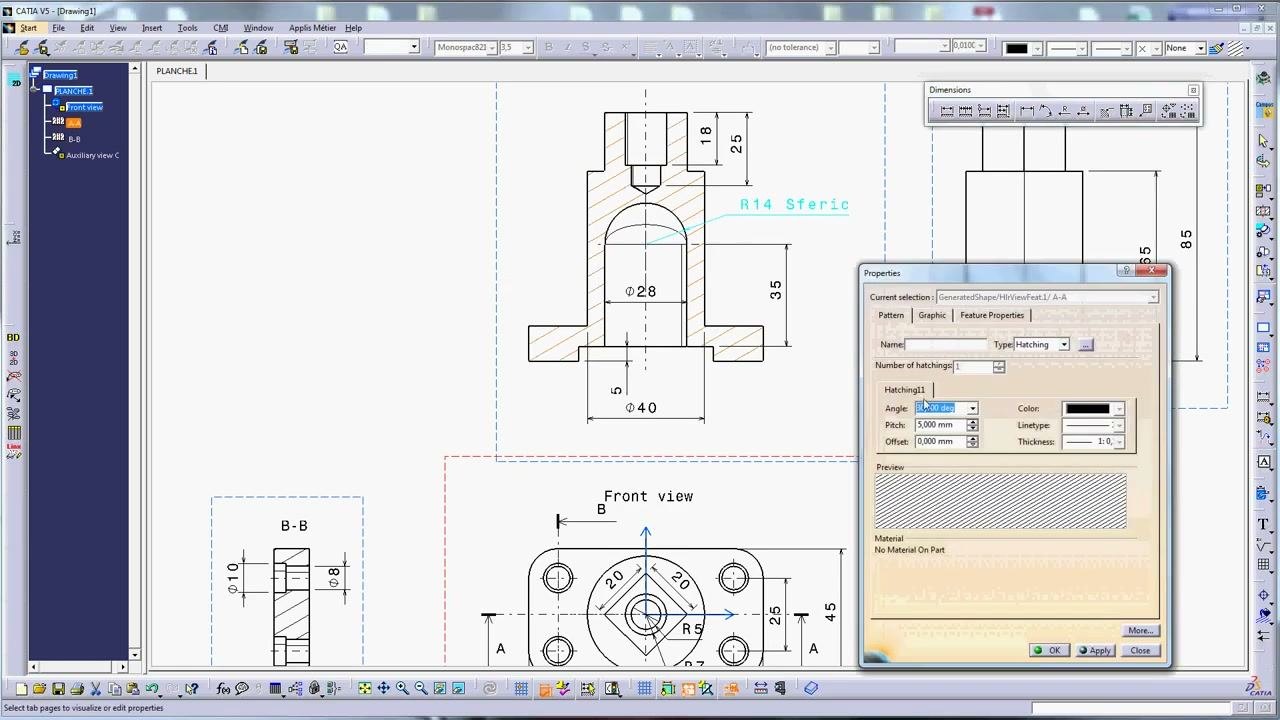
Step 23: Apply hatching to a section view
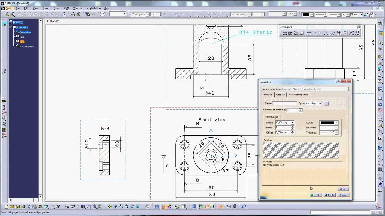
Double-click or right-click a sectioned area, for example A-A or B-B, to open the Properties dialog. In the Properties window, go to the Feature Properties tab and select Hatching.
Set the hatching parameters:
- Angle: 45.000 deg
- Pitch: 5.000 mm (or 4.000 mm, as shown in later steps)
- Offset: 0.000 mm
- Color: Black
- Linetype: Solid
- Thickness: 1.0
Preview the hatching pattern in the dialog. Then click Apply or OK to apply the hatching to the selected section.
Step 24: Repeat the hatching for other sections
Select another section view, for example B-B. Open the Properties dialog and set the hatching parameters as you did for the first section. Confirm that the hatching is applied and visible in the section view.
Set the isometric view properties
Step 25: Open the properties for the isometric view
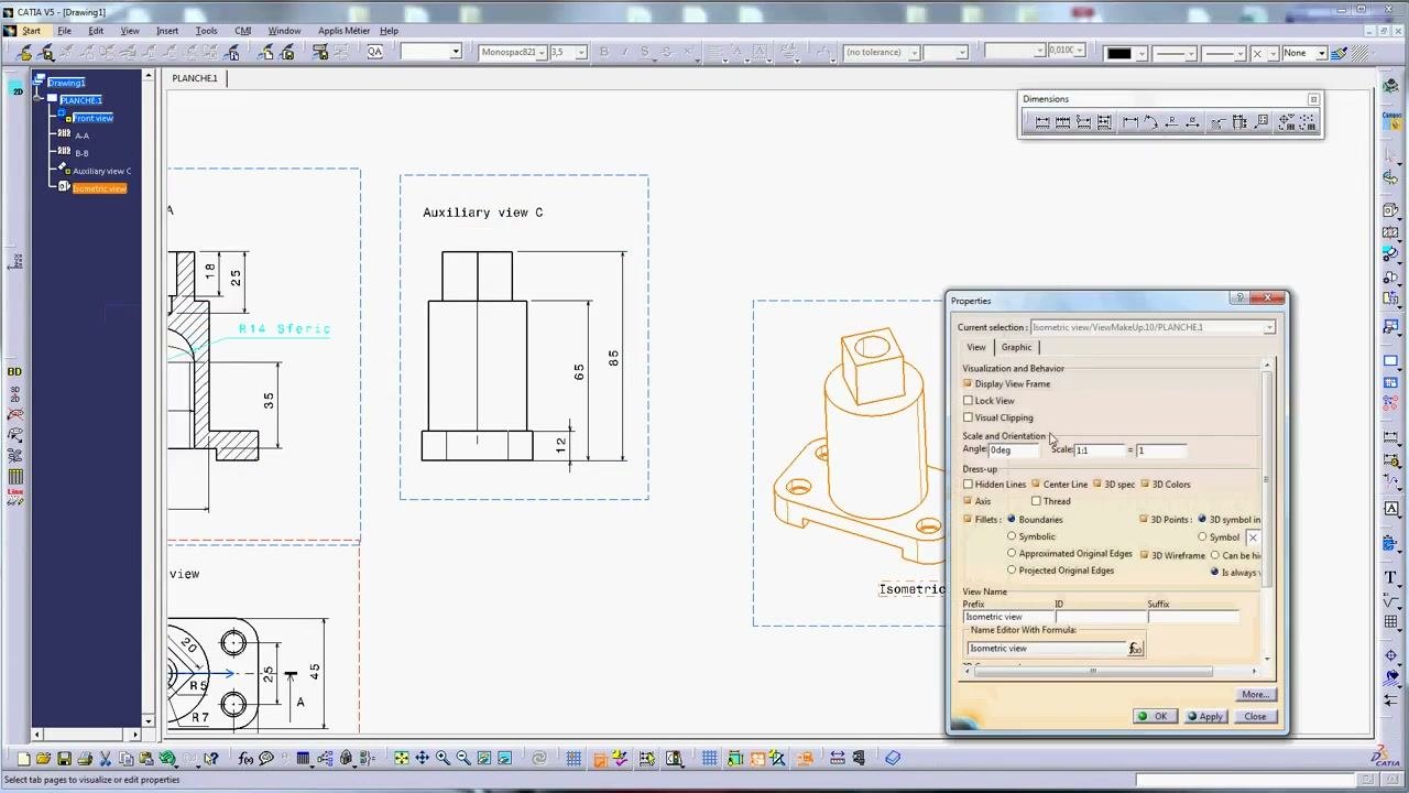
Right-click or double-click the isometric view boundary to open the Properties dialog. The window is focused on the isometric view, which stays highlighted on the drawing.
The dialog offers these options:
- Visualization and Behavior: Display View Frame, Lock View, Visual Clipping
- Scale and Orientation: Angle 0 deg, Scale 1
- Dress-up options: Hidden Lines, Center Line, 3D spec, 3D Colors, Fillets, Boundaries, 3D Points, Symbol, and more
- View Name: currently "Isometric view"
Step 26: Adjust the isometric view settings
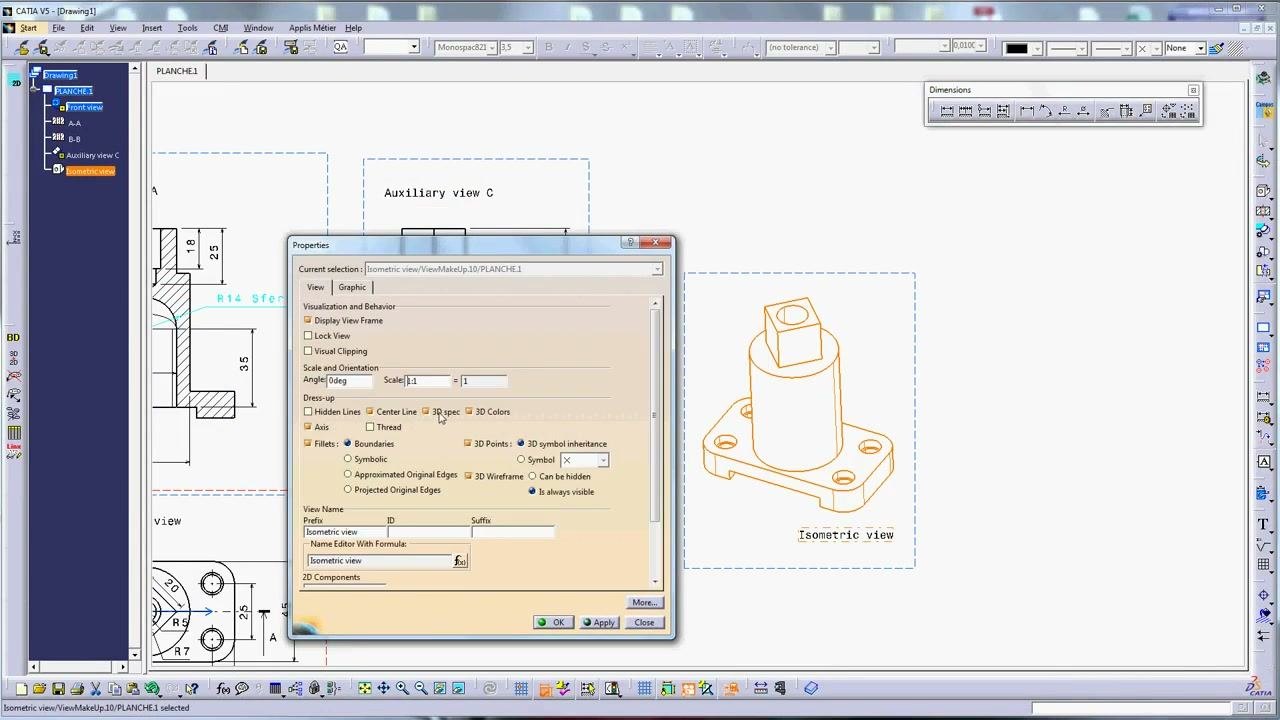
In the Properties dialog, review and change these settings as needed:
- Scale and Orientation: Set Angle to 0 deg and Scale to 1 for a true-size isometric view.
- Dress-up options: Check or clear options such as Hidden Lines, Center Line, 3D spec (checked), and 3D Colors (checked). You can also set Fillets (Boundaries, Symbolic, Approximated Original Edges, Projected Original Edges), 3D Points, 3D symbol inheritance, and Symbol.
- 3D Wireframe: Choose Can be hidden or Is always visible.
- View name: Confirm or edit the name in the Name Editor With Formula field. It currently reads "Isometric view".
The dialog stays open for further adjustments.
Step 27: Apply and confirm your changes
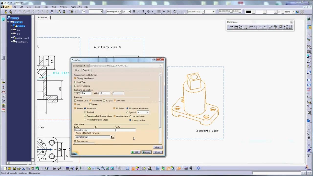
Click Apply to preview the changes in the drawing. Click OK to confirm and close the Properties dialog.
The isometric view updates according to the selected properties, such as 3D spec and 3D Colors. The drawing now shows the customized isometric view alongside the other views.
Summary
You now know how to create a 2D drawing in CATIA V5. You opened a drawing sheet and inserted a front view. You added section views A-A and B-B and an auxiliary view C. You dimensioned each view with linear, diameter, and radius dimensions, including the "R14 Sferic" annotation. You also applied hatching to the section views and customized the isometric view properties.
What's next
- Review the drawing for completeness and accuracy.
- Add any necessary notes, tolerances, or finishing details.
- Save and export the finished drawing as required.
Generation details: cost, quality tiers
Docsie billed 4,000 credits ($2.80) to analyze this 8-minute video at standard quality. The rewrite, template fill and Word/PDF exports were included. The same video at each quality tier:
| Quality | Frames sampled | Credits | Approx. cost |
|---|---|---|---|
| Draft | every 16-30 s | 2,000 | $1.40 |
| Standard (this guide) | every 8-15 s | 4,000 | $2.80 |
| Detailed | every 4-7 s | 8,000 | $5.60 |
| Ultra | every 1-3 s | 16,000 | $11.20 |
Credits priced at $0.70 per 1,000; plans include a monthly allowance. Enterprise customers on on-premise or bring-your-own-model deployments run this on their own inference and pay no per-video credits.
Generated by Docsie Video-to-Docs on 2026-11-15 from a 7-minute video. Screenshots are frames from the source video and belong to their creator, Catia V5-V6 Tutorials, whose original is embedded above. If you own this video and want the guide removed or credited differently, contact us and we will act within one business day.