
How to Convert a Surface to Solid in CATIA
This guide shows you how to convert a surface to solid in CATIA V5. You build a multi-section surface from two spline curves, then apply thickness to turn that surface into a solid part. You work in the Generative Shape Design workbench from start to finish.
Video: How to Convert Surface to solid body in Catia V5 | surface body to solid body | Catia V5R21 by Vyadh Aerospace (2021). All credit for the demonstration goes to the creator; watch the original on YouTube. The written guide below was generated from this video by Docsie. Creator? Request a change or removal.
This guide shows you how to convert a surface to solid in CATIA V5. You build a multi-section surface from two spline curves, then apply thickness to turn that surface into a solid part. You work in the Generative Shape Design workbench from start to finish.
Prerequisites
- CATIA V5 is installed and open.
- A product is loaded in the main workspace. The window title shows the product name, for example
[Product1.2]. - The workspace is empty except for the default axes and the product tree on the left.
Launch CATIA V5 and confirm the product is loaded
- Open CATIA V5.
- Check that the main workspace shows the loaded product.
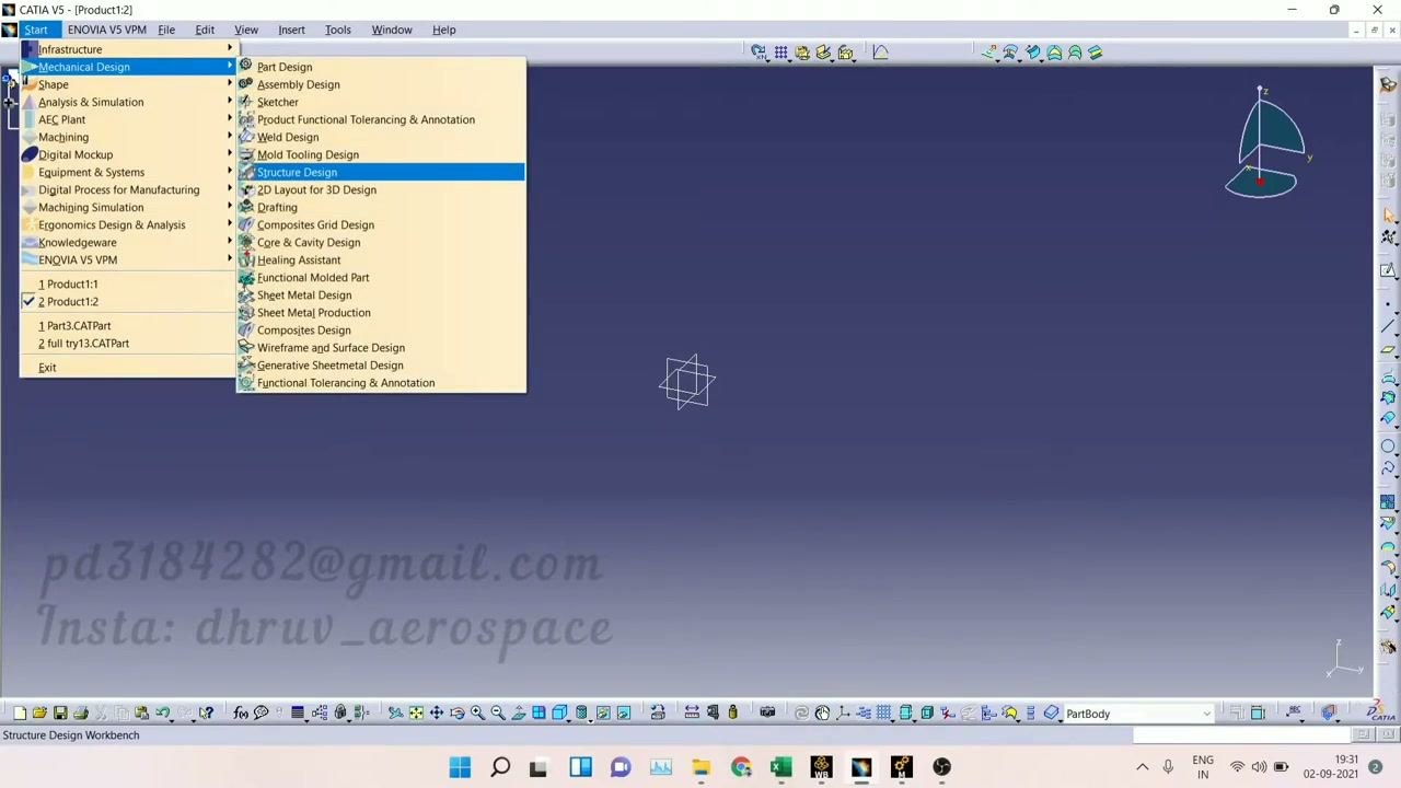
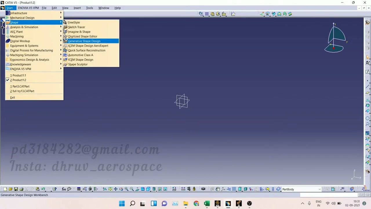
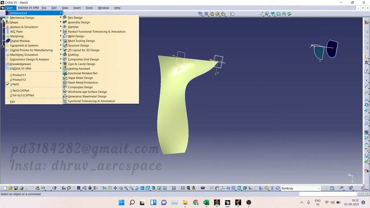
Switch to the Generative Shape Design workbench
- Click the Start menu.
- Hover over Shape to expand its submenu.
- Select Generative Shape Design.
Draw the first spline curve
- In the Generative Shape Design workbench, select the spline tool.
- Click to place control points and shape the spline as needed.
The curve appears in the workspace with its control points and coordinate axes. The product tree shows the part structure, for example Part2, xy plane, yz plane, zx plane, and PartBody.
Adjust the first spline curve
- Move the control points to refine the curve shape.
The curve updates dynamically as you adjust the points. PartBody may be highlighted in the product tree as the active part.
Create an offset plane
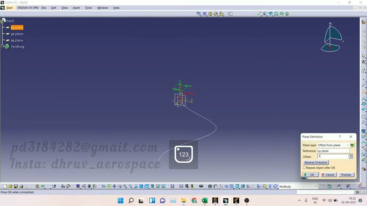
- Select the
xy planein the product tree. - Open the Plane Definition dialog.
- Set Plane type to Offset from plane.
- Set Reference to
xy plane. - Enter an Offset value, for example
1. - Click OK to create the new plane.
Draw a second spline curve on the new plane
- Switch to the new offset plane.
- Use the spline tool to draw a second curve, similar to the first.
- Place control points and shape the curve as needed.
The workspace now displays two spline curves on different planes.
Refine the second spline curve
- Adjust the control points of the second spline until you reach the shape you want.
The workspace shows both curves, each with its own control points and coordinate axes. Control point values, for example H: 8.079mm and V: 74.44mm, may appear near the points.
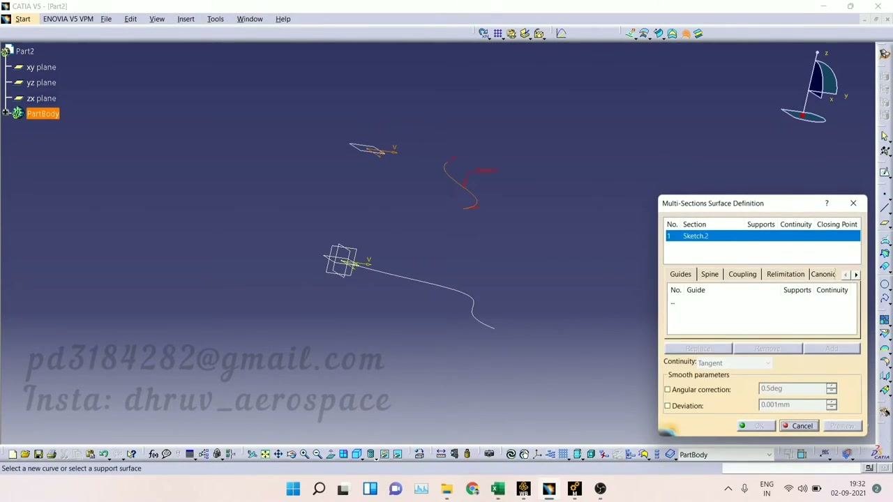
Open the Multi-Sections Surface Definition dialog and add the first section
With both splines created, you can build the surface that you later convert to a solid.
- Open the Multi-Sections Surface Definition dialog.
- Add the first section, for example
Sketch.2. - Set Continuity to Tangent.
- Set Deviation to
0.001mm.
The dialog shows the selected section and options for guides, spine, coupling, relimitation, and continuity.
Add the second section and generate the surface
- In the Multi-Sections Surface Definition dialog, add the second section, for example
Sketch.1. - Check that both sections are listed.
- Confirm that the continuity and deviation settings are correct.
- Click OK to generate the surface.
Select the multi-section surface
Next, apply thickness to convert the surface to a solid in CATIA.
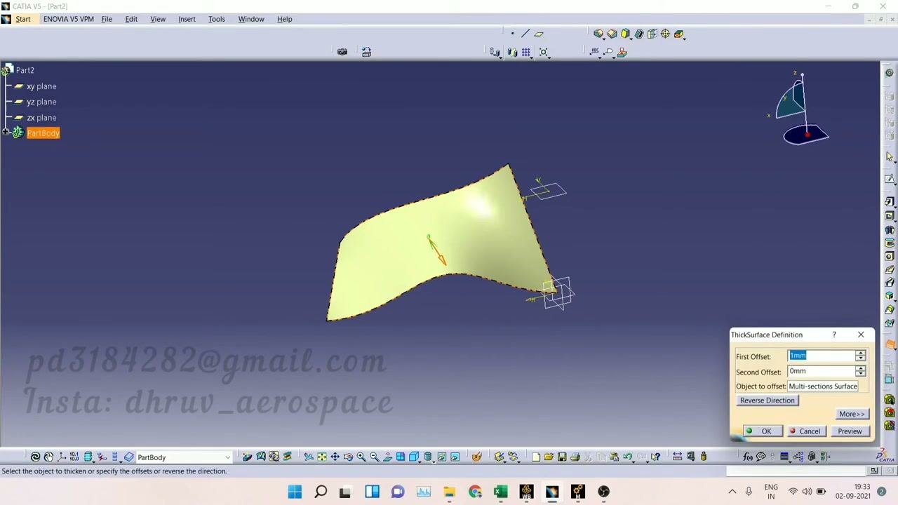
- Make sure the multi-section surface is visible and highlighted in the workspace.
The surface appears as a smooth, yellow-shaded patch in the 3D view. The product tree shows Part2 > PartBody with the multi-section surface listed. No dialog boxes are open at this stage.
Open the ThickSurface Definition dialog
- Start the thickening operation. You typically do this by selecting the "Thick Surface" tool from the toolbar.
The ThickSurface Definition dialog appears in the lower right corner and shows these fields:
- First Offset:
1mm - Second Offset:
0mm - Object to offset:
Multi-sections Surface
The surface is highlighted in the workspace, and an arrow indicates the direction of the thickness. The dialog also provides Reverse Direction, OK, Cancel, and Preview.
Preview the thickened surface
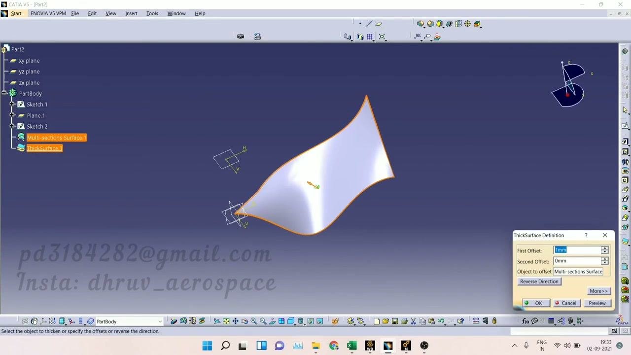
- Click Preview in the ThickSurface Definition dialog.
The surface updates in the workspace and appears as a solid with visible thickness. The product tree stays visible, and the thickened surface is highlighted.
Apply the thickness to finish the surface-to-solid conversion
- Click OK in the ThickSurface Definition dialog.
The dialog closes, and the thickened surface remains in the workspace with a shiny, solid appearance. The product tree now lists both Multi-sections Surface.1 and ThickSurface.1 under PartBody, both highlighted.
Inspect the final solid
- Rotate or pan the view to inspect the thickened solid from different angles.
The workspace shows the completed part, and the product tree confirms the structure. No dialogs are open, and the thickened solid is clearly visible.
Summary
You now know how to convert a surface to solid in CATIA V5. You drew two spline curves on offset planes and joined them into a multi-section surface. You then applied thickness with the ThickSurface Definition dialog, which turned the surface into a solid part.
Generation details: cost, quality tiers
Docsie billed 1,500 credits ($1.05) to analyze this 3-minute video at standard quality. The rewrite, template fill and Word/PDF exports were included. The same video at each quality tier:
| Quality | Frames sampled | Credits | Approx. cost |
|---|---|---|---|
| Draft | every 16-30 s | 750 | $0.52 |
| Standard (this guide) | every 8-15 s | 1,500 | $1.05 |
| Detailed | every 4-7 s | 3,000 | $2.10 |
| Ultra | every 1-3 s | 6,000 | $4.20 |
Credits priced at $0.70 per 1,000; plans include a monthly allowance. Enterprise customers on on-premise or bring-your-own-model deployments run this on their own inference and pay no per-video credits.
Generated by Docsie Video-to-Docs on 2026-11-15 from a 2-minute video. Screenshots are frames from the source video and belong to their creator, Vyadh Aerospace, whose original is embedded above. If you own this video and want the guide removed or credited differently, contact us and we will act within one business day.