
How to Convert a 3D Model to 2D Drawing in CATIA
This guide shows you how to convert a 3D model to a 2D drawing in CATIA V5, using a sprocket gear as the example. You open the finished part, switch to the Drafting workbench, and insert the front, projection, and isometric views. You then add dimensions, annotations, and a title block, and export the finished drawing as a PDF.
Video: 3 how to convert 3D model to 2D drawing catia V5 by Mesfin Mamuye (2022). All credit for the demonstration goes to the creator; watch the original on YouTube. The written guide below was generated from this video by Docsie. Creator? Request a change or removal.
This guide shows you how to convert a 3D model to a 2D drawing in CATIA V5, using a sprocket gear as the example. You open the finished part, switch to the Drafting workbench, and insert the front, projection, and isometric views. You then add dimensions, annotations, and a title block, and export the finished drawing as a PDF.
Prerequisites
- CATIA V5 is installed and running.
- Your sprocket gear is fully modeled and ready for drafting.
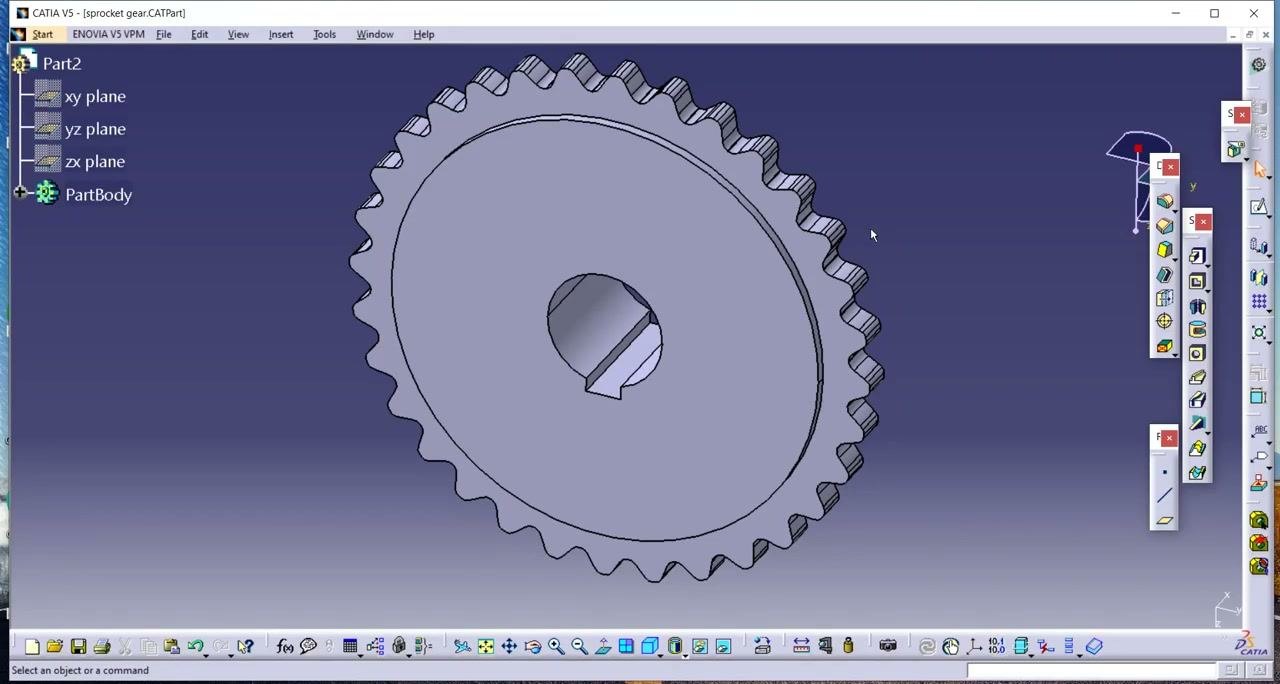
- The part is open in the workspace, with the part tree (xy plane, yz plane, zx plane, PartBody) on the left.
Open the model and create a new drawing
Step 1: Open the final 3D model
Make sure the sprocket gear is fully modeled and open in CATIA V5. The model appears in the workspace, and the part tree is on the left. Confirm the model is complete before you start drafting.
Step 2: Switch to the Drafting workbench
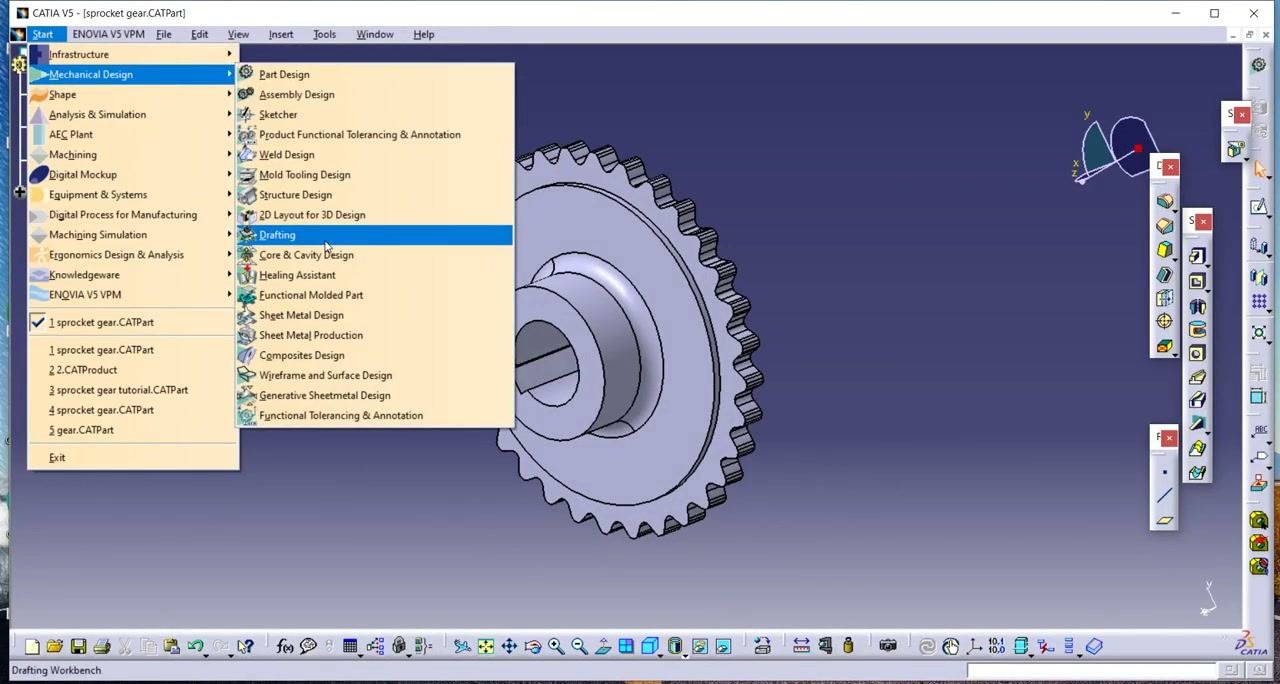
To convert the 3D model to a 2D drawing in CATIA, start in the Drafting workbench.
- Click the Start menu at the top.
- Hover over Mechanical Design in the dropdown.
- Click Drafting in the list of workbenches.
The software may take a moment to switch. Wait until the interface responds and the drafting tools are available.
Step 3: Start a new drawing
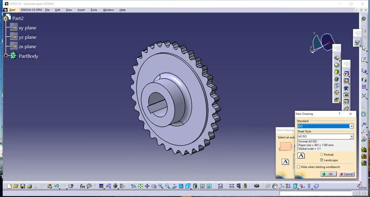
When prompted, the New Drawing Creation dialog appears.
- Select an automatic layout for your drawing. For example, choose the layout with front, bottom, and right views.
- Confirm the paper size is 210 x 297 mm and the global scale is 1:1.
- Click OK, or click Modify to adjust the settings further.
Step 4: Adjust the paper size and orientation
In the New Drawing dialog, set your sheet options.
- Set the standard to ISO.
- Choose the sheet style you need (for example, A0 ISO).
- Select Portrait or Landscape, as required.
- Click OK to confirm.
Insert and scale the front view
Step 5: Start the front view tool
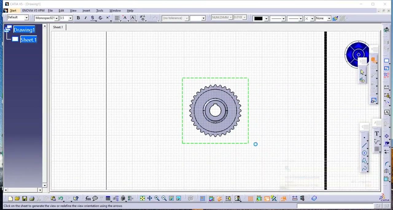
In the Drafting workbench, find the view creation toolbar on the right side of the screen. Select the Front View tool (hover text: "Advanced Front View"). Click the Advanced Front View icon to begin inserting the front view of your 3D sprocket gear.
Step 6: Select the reference face in the 3D model
Switch to the 3D model window so you can pick the face for the front view.
- Click Window in the top menu.
- In the dropdown, select your 3D model file (for example,
sprocket gear.CATPart) to bring the model to the foreground. - Click the face of the sprocket gear that you want to use as the front view reference.
The selected face is highlighted, and the software generates a preview of the front view on your drawing sheet.
Step 7: Place the front view on the drawing sheet
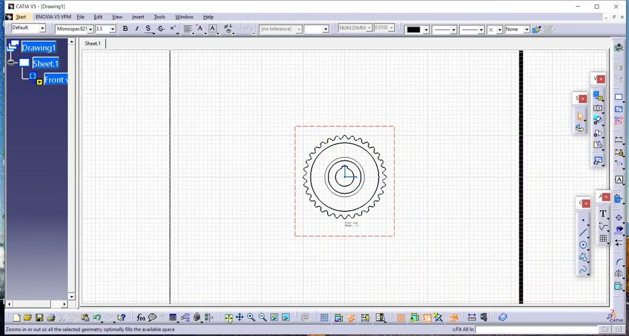
Return to the drawing sheet and click the location where you want the front view. The front view appears, enclosed in a dashed selection box.
Step 8: Move the front view
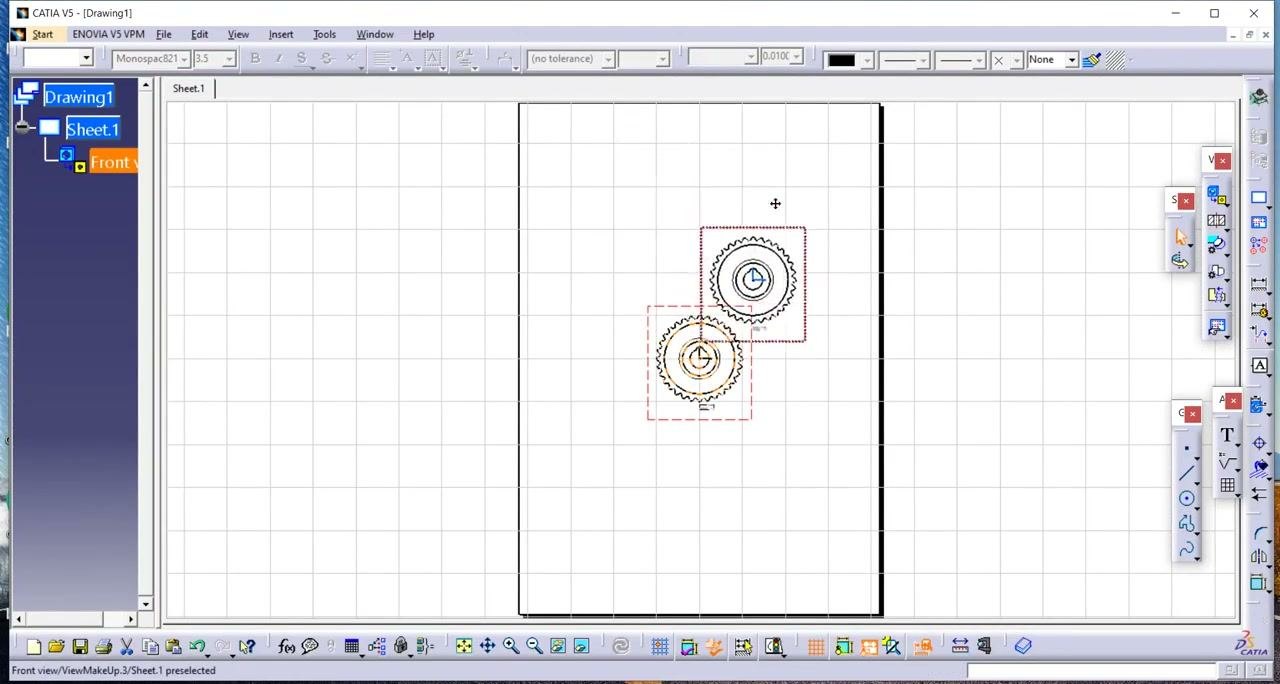
Click and drag the front view to reposition it on the sheet. Arrange it for the best placement and clarity.
Step 9: Change the scale of the front view
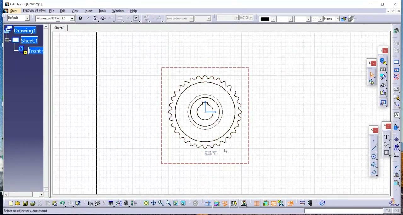
First, check the default scale. The label below the front view shows the current scale (for example, "Front view Scale 1:1").
Then change it.
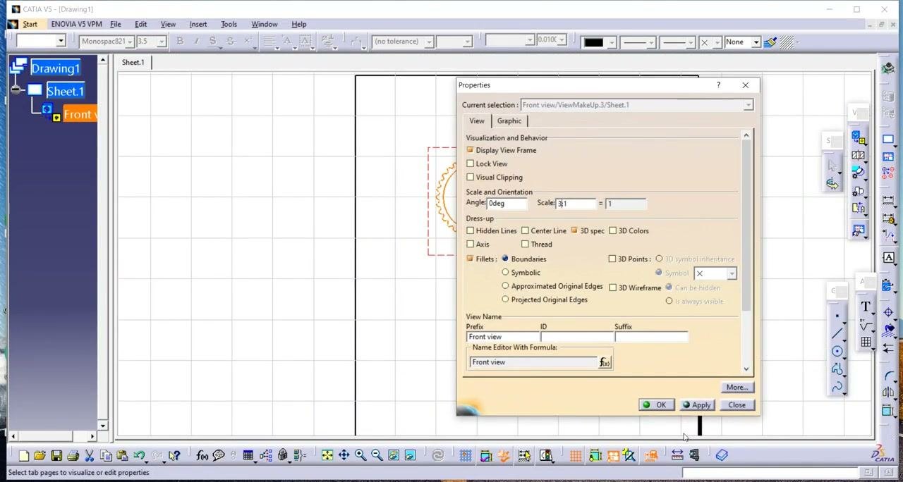
- Right-click the front view and select Properties.
- In the Properties dialog, open the View tab and find the Scale field.
- Enter the scale you want (for example, change
1:1to3:1to enlarge the view). - Click Apply or OK.
You have now inserted and scaled the front view of the sprocket gear on the 2D drawing sheet. Continue with the projection views below.
Add projection views
Step 10: Set the projection method
- Right-click the sheet background and select Properties.
- In the Properties dialog, find the Projection Method section.
- Choose First angle standard or Third angle standard, as your drawing requires.
- Click Apply or OK.
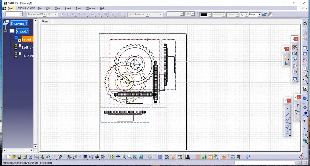
Step 11: Insert a projection (side) view
- In the Drafting workbench, select the Projection View tool from the right-side toolbar.
- Click the front view to generate a projection view (for example, a left or right side view).
- Move the cursor to the location you want, typically to the right of the front view, and click to place the side view.
Keep a suitable gap between the front and side views for clarity.
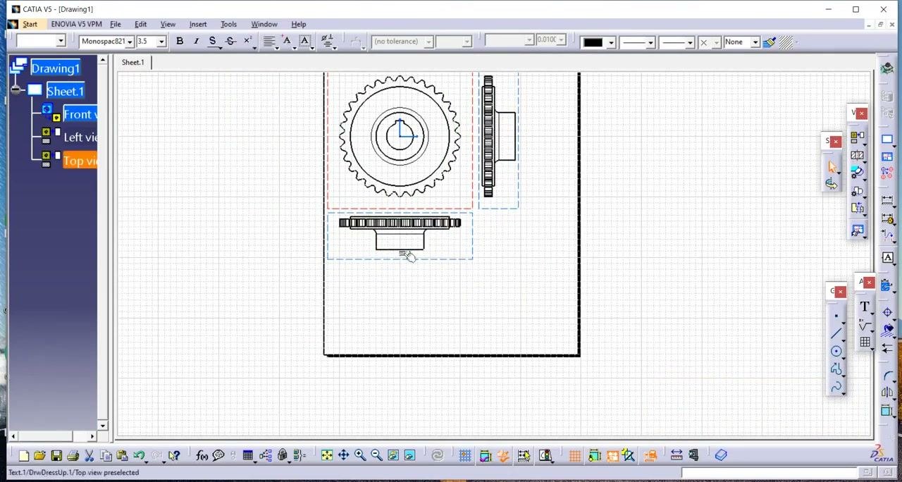
Step 12: Insert additional projection views
Use the Projection View tool again to add more views, such as a top or bottom view. Click below the front view to insert a top or bottom projection view. Arrange the front, side, and top views according to standard engineering drawing conventions.
Step 13: Arrange and align the principal views
Adjust the positions of the front, side, and top views so they are aligned and evenly spaced. Confirm that all three principal views are clearly displayed on the sheet.
Step 14: Zoom in to verify detail
Zoom in on the drawing sheet to inspect the alignment and detail of each view. Make sure all features are accurately represented and the views are correctly scaled.
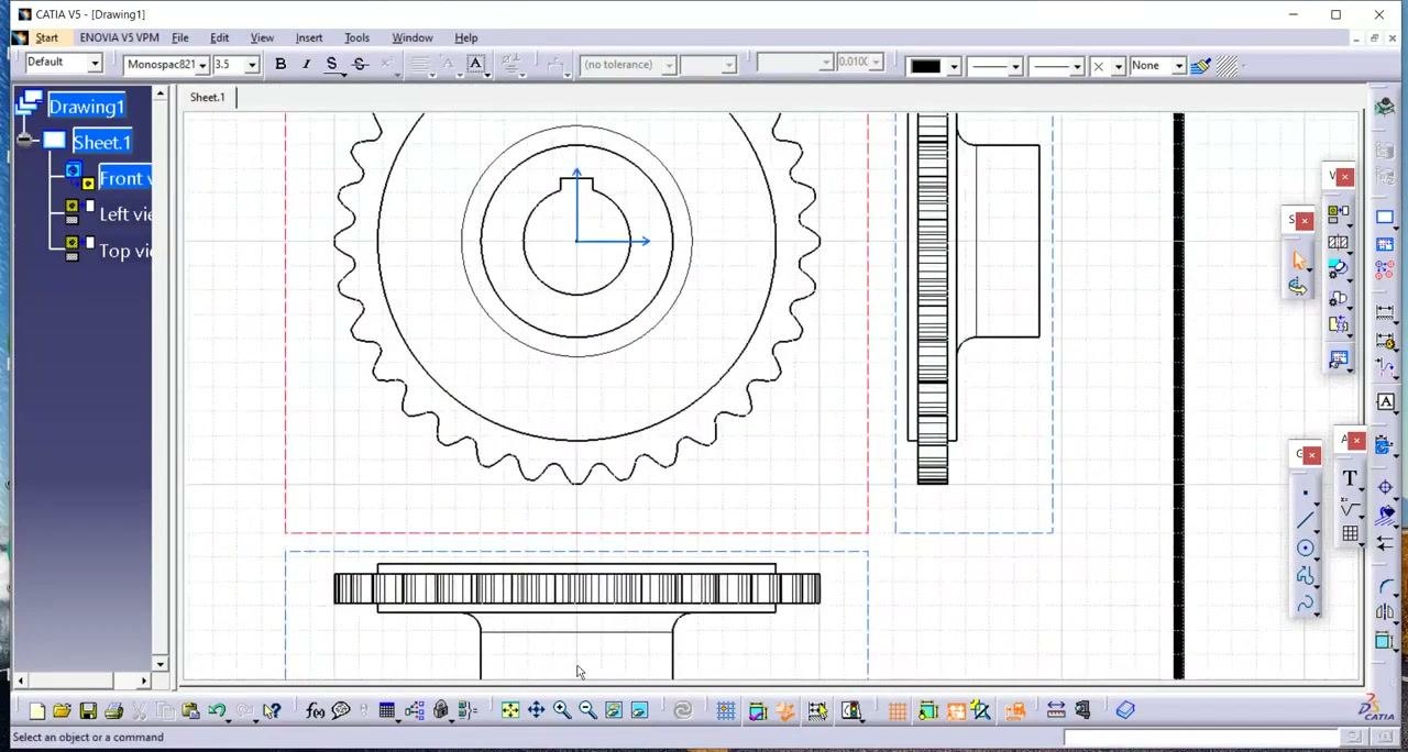
Step 15: Customize view properties
You can control hidden lines, axes, center lines, and threads for each view.
- Select each view (front, side, top) in the tree or on the sheet.
- Right-click and choose Properties.
- In the Properties dialog, enable or disable display options such as hidden lines, axis lines, center lines, and thread representation, as needed for technical clarity.
Step 16: Confirm the view settings
The Properties dialog shows options for visualization and behavior, scale and orientation, and dress-up features. Confirm or adjust these settings:
- Angle: 0 deg
- Scale: 2:1
- Center Line checked under Dress-up
- Other options, such as Hidden Lines, Axis, Thread, and Fillets, as needed
Click OK or Update to apply the changes. You can follow the update progress in the status window at the bottom right.
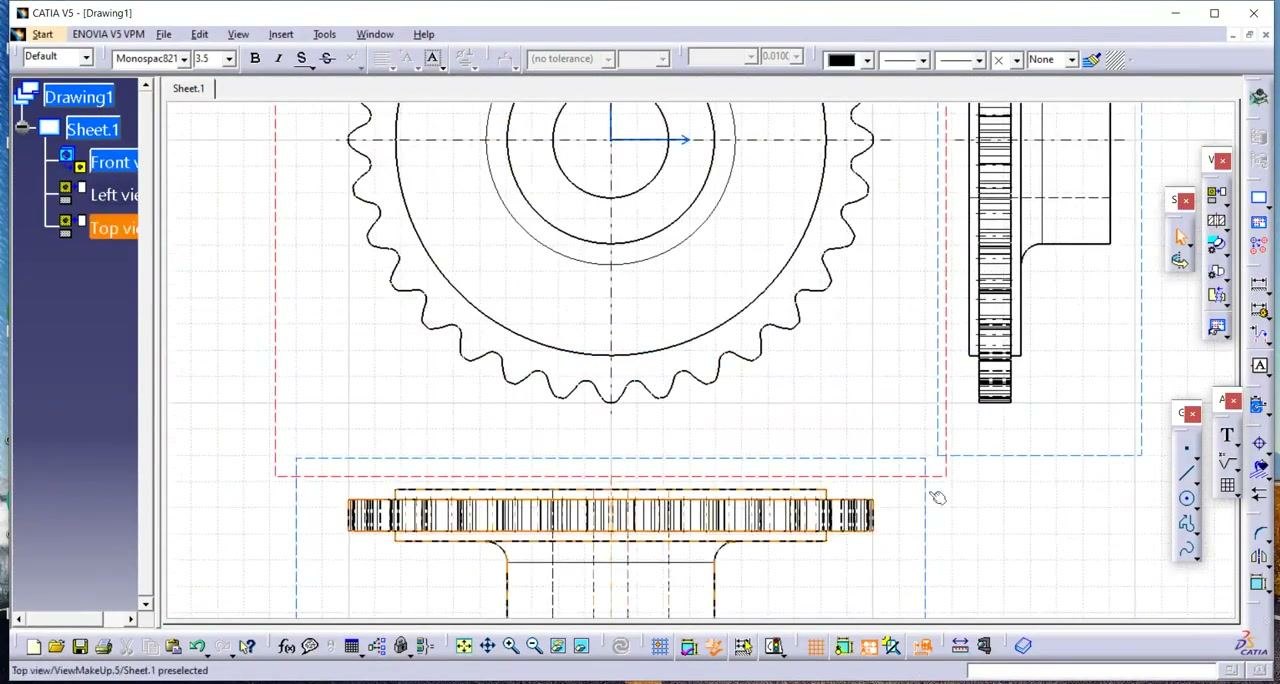
The drawing area now shows the gear with visible center lines and axes (XOX axis). Confirm that all properties display as expected.
Add dimensions and annotations
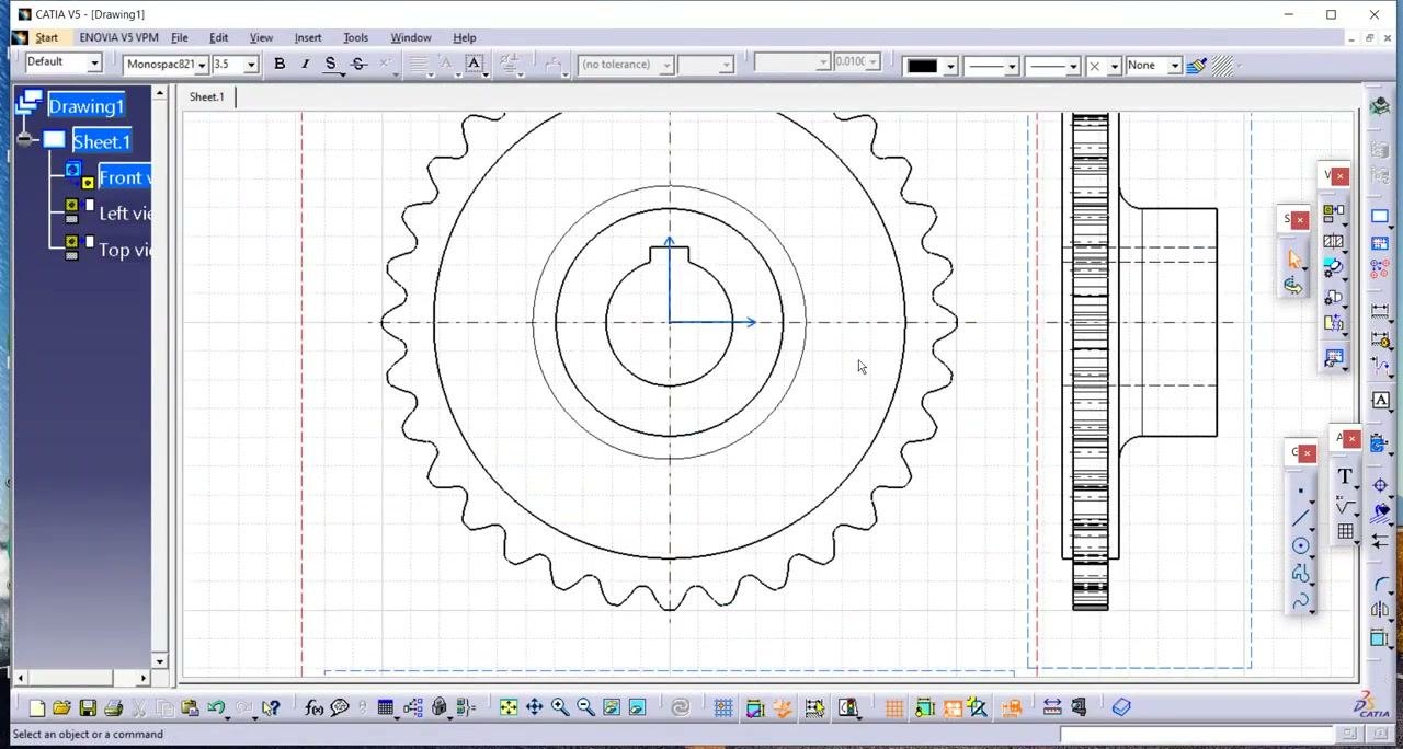
Step 17: Start dimensioning
Select the dimensioning tool from the right-side toolbar or the floating dimension palette. The drawing is now ready for dimensioning, and no dimension lines appear yet.
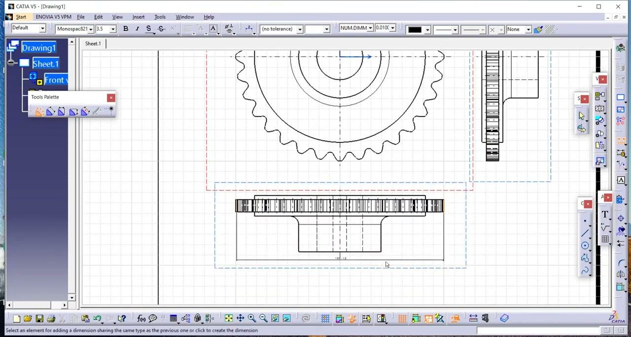
Step 18: Create a linear dimension between two points
Select the view you want, for example the side view of the gear. Click the first point, then the second point. The dimension line appears between the two points.
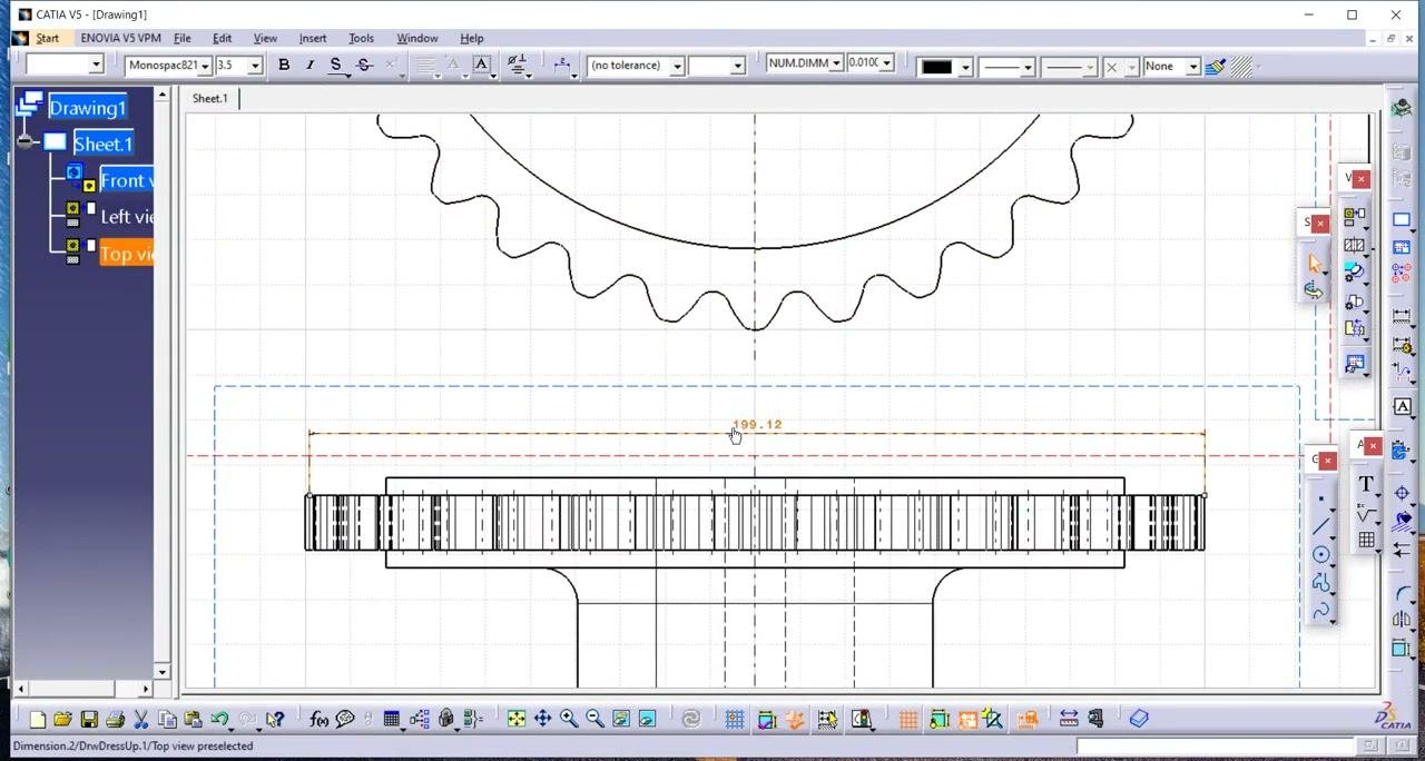
Step 19: Add a diametral dimension
Select the diametral dimension tool from the palette, then click the circular feature you want to dimension. The diametral dimension (for example, 199.12) appears in the drawing area.
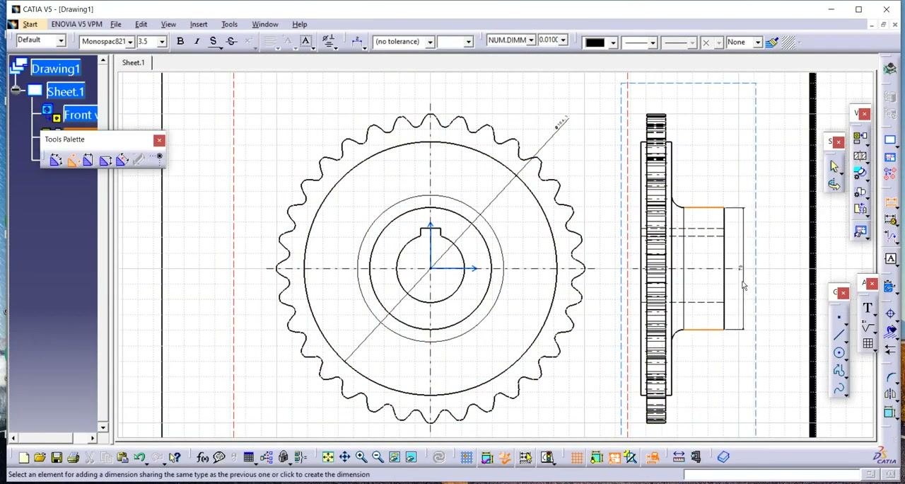
Step 20: Add more dimensions or annotations
Use the dimensioning tools to add further dimensions. Use the text tool to add annotations or numbers, such as a label that indicates a specific feature or count.
Step 21: Add a text annotation for the number of teeth
- Select the text tool from the right-side toolbar.
- Click in the drawing area above the gear to place the annotation.
- Enter "Number of tooth" in the Text Editor dialog box.
- Click OK to confirm and place the text.
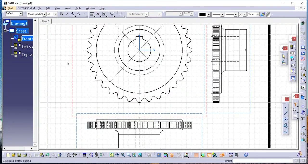
Step 22: Edit and position the annotation
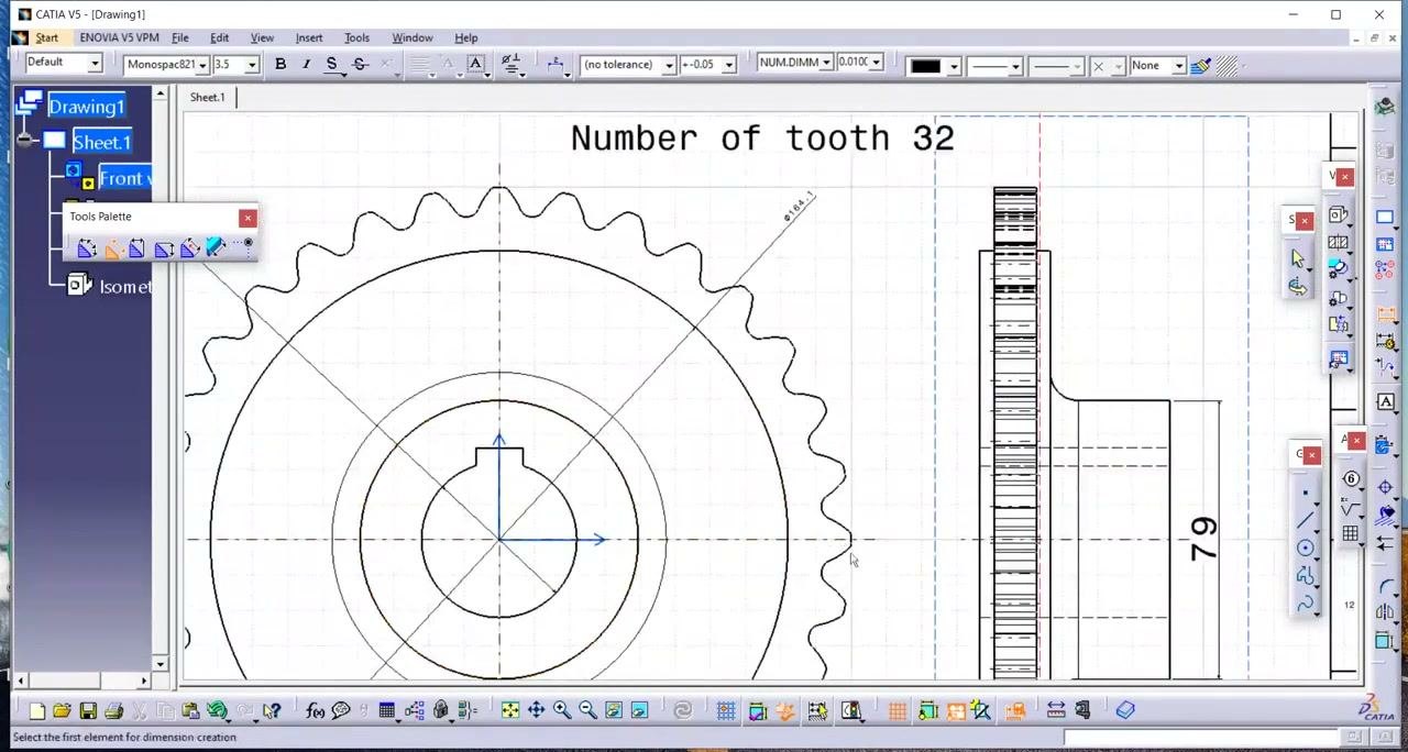
Update the annotation to the correct value if needed (for example, "Number of tooth 32"). Use the toolbar at the top to adjust the font size and style (for example, set the font size to 14.0). Move the annotation to the location you want above the gear drawing.
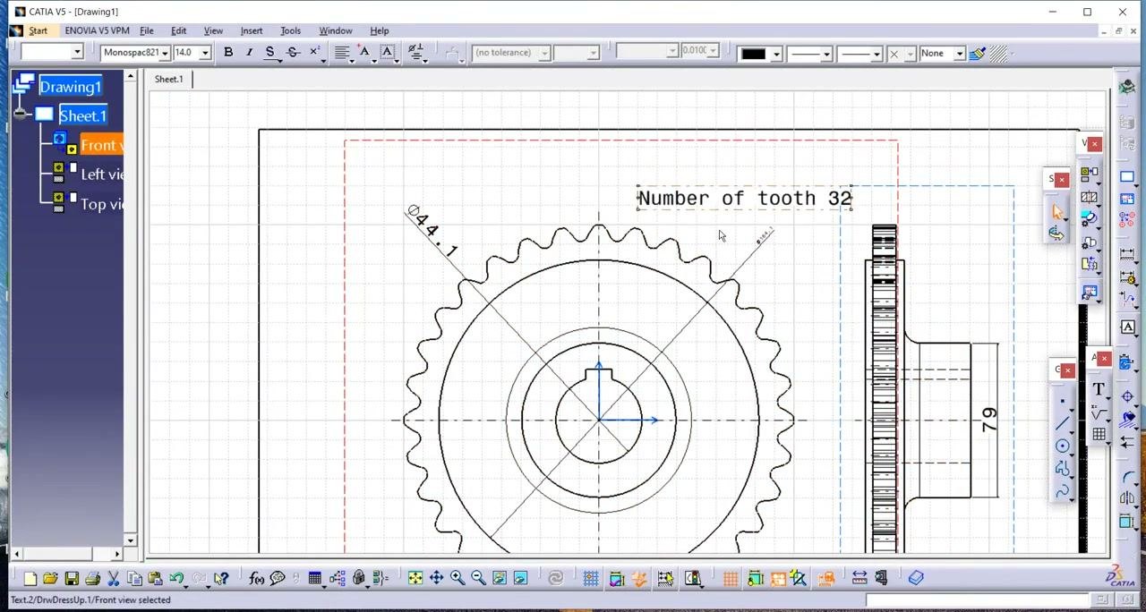
Step 23: Review the updated layout
Check that the annotation is clearly visible and correctly positioned. Confirm that all dimension lines (for example, diameter 44.1 and width 79) and annotations are present and legible. The drawing now shows the gear with all required dimensions and the "Number of tooth 32" annotation.
Step 24: Zoom in or out for clarity
Use the zoom tool in the bottom toolbar to focus on specific areas of the drawing. Verify that all details stay clear and that annotations do not overlap other elements.
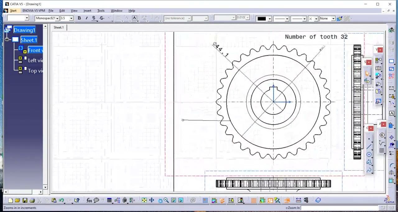
Add the frame and title block
Step 25: Switch to the sheet background
- Click Edit in the top menu.
- Select Sheet Background at the bottom of the dropdown.
This lets you modify the drawing's frame and title block area.
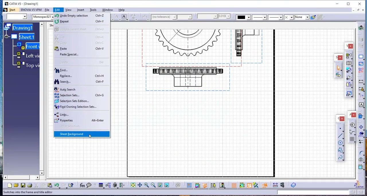
Step 26: Insert a title block
After you switch to the sheet background, the Manage Frame And Title Block dialog appears.
- Open the Style of Title Block dropdown.
- Select a style, such as Drawing Titleblock Sample 2.
- Under Action, make sure Create is selected.
- Check the style in the dialog's preview pane.
Click OK or Apply to insert the title block. It appears at the bottom of the sheet with default information: company name, drawing title, author, date, size, drawing number, revision, scale, weight, and sheet number.
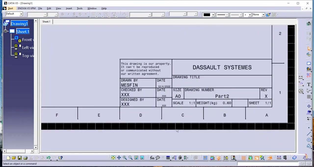
Step 27: Edit the title block information
Click any text field in the title block to activate it for editing. For example, click the company name field ("DASSAULT SYSTEMES") or the property notice. Use the text editing tools at the top (font size, style, and so on) as needed.
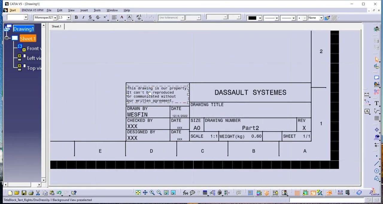
To update the company name or another field:
- Select the field and enter the new value (for example, change "DASSAULT SYSTEMES" to "AAIT").
- Type the new text in the Text Editor dialog that appears.
- Click OK to confirm.
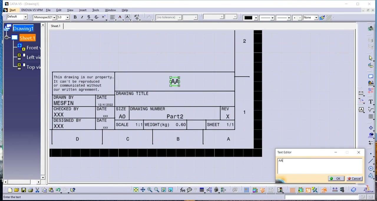
Verify that the new value (for example, "AAIT") appears in the title block, and that all other required fields are accurate and current.
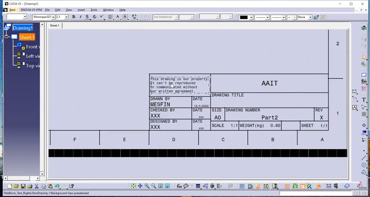
Step 28: Fill out the title block with drawing information
Enter the following details in the title block:
- Drawn By: MESFIN
- Date: 12/4/2022
- Checked By: john
- Date: xxx (replace with the actual date if available)
- Designed By: XXX (replace with the actual name if available)
- Date: xxx (replace with the actual date if available)
- Drawing Title: AAIT
- Size: A0
- Drawing Number: Part2
- Revision: X
- Scale: 1:1
- Weight (kg): 0.60
- Sheet: 1/1
Make sure all fields are completed. Confirm that the note "This drawing is our property. It can't be reproduced or communicated without our written agreement." is present. Verify that the sheet grid (A-F, 1-2) is visible for reference.
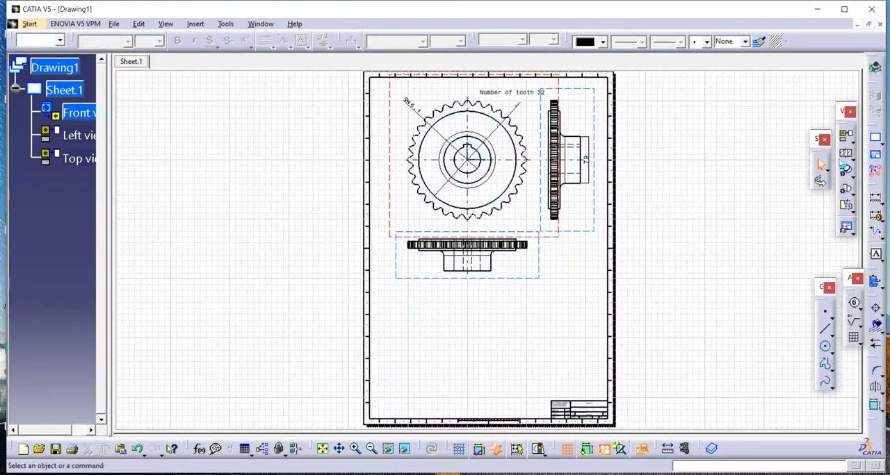
Then confirm that all entered information (paper size, weight, sheet number, and so on) displays correctly. Double-check accuracy and completeness before you continue.
Add an isometric view
Step 29: Activate the isometric view tool
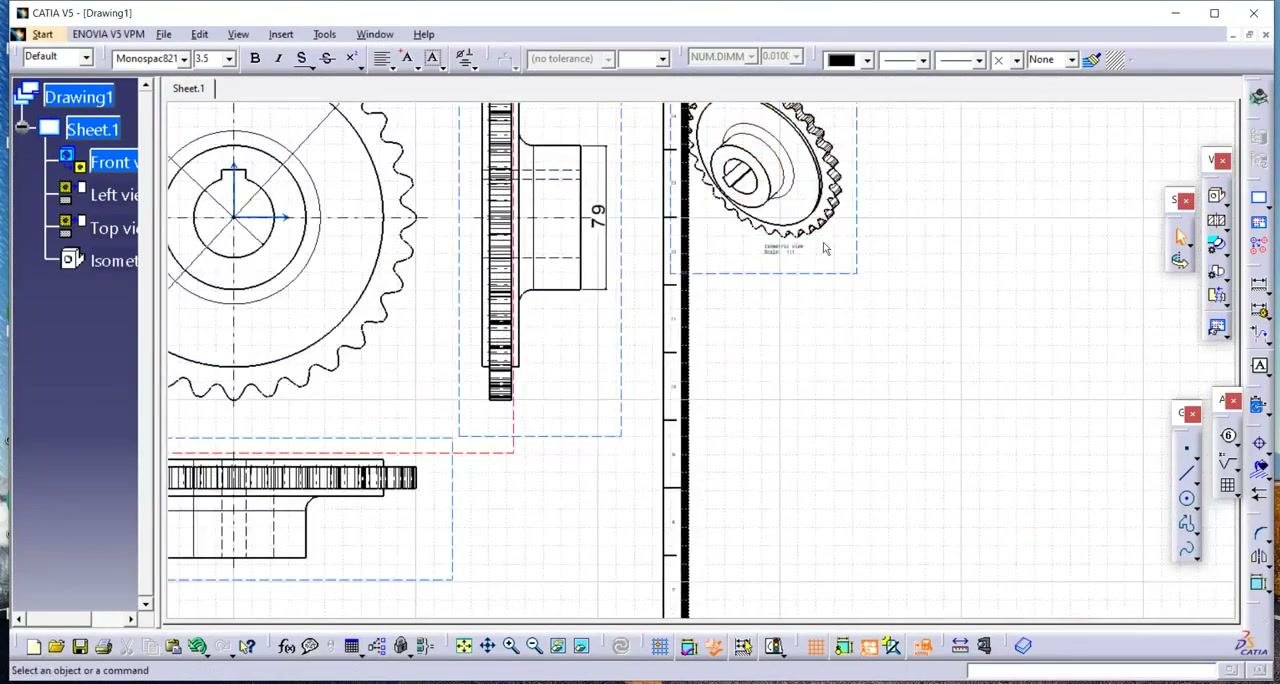
Find the isometric icon in the CATIA V5 toolbar and click it to activate the isometric view function. In the tree on the left, make sure Isometric is selected under Sheet.1.
Step 30: Switch to the sprocket gear part window
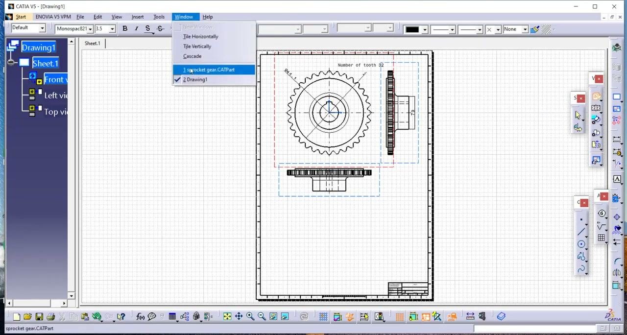
Click Window in the top menu and select sprocket gear.CATPart from the dropdown to switch to the part file. This lets you drag the isometric view into your drawing sheet.
Step 31: Drag the isometric view onto the sheet
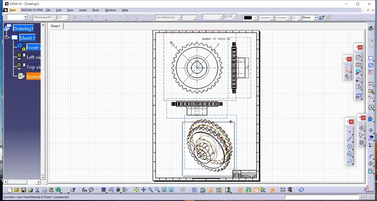
Click and drag the isometric view of the sprocket gear onto the drawing sheet. Position it in the lower section of the sheet so it does not overlap other views. Adjust the placement for clarity and presentation.
Step 32: Adjust and finalize the isometric view
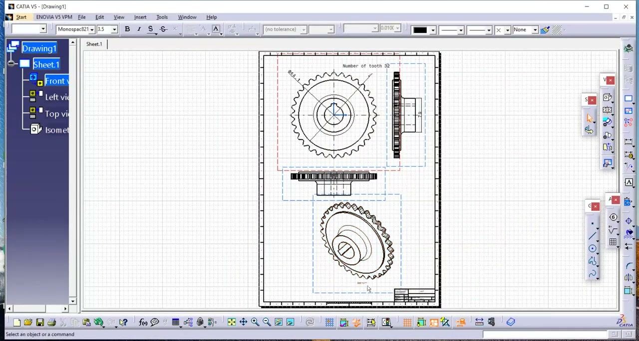
Resize or reposition the isometric view if needed for the best layout. Make sure it is clearly visible and does not obscure other drawing elements. Confirm that all views (front, left, top, isometric) are aligned and labeled.
Export the drawing as a PDF
Step 33: Review the drawing before export
Inspect the drawing sheet in CATIA V5 to make sure all required details are present. Confirm that dimensions (for example, shaft diameter), annotations (for example, "Number of tooth 32"), and all views are clearly visible. The drawing should include the front, side, and isometric views of the sprocket gear.
Step 34: Open Save As
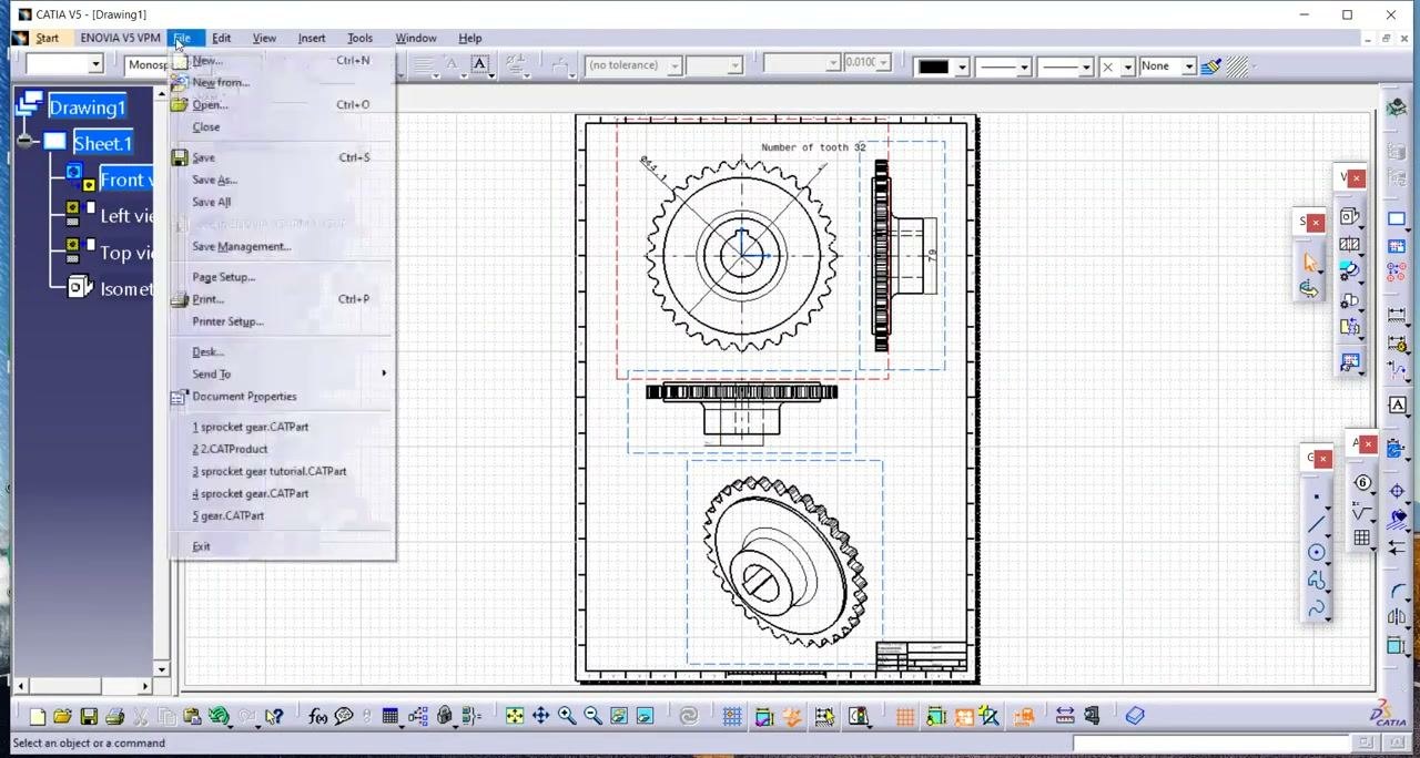
Click File in the CATIA V5 menu at the top left. The dropdown shows options such as New, Open, Save, Save As, and Print. Click Save As... to open the Save As dialog, where you choose the file format and destination folder.
Step 35: Choose the export location and file type
- In the Save As dialog, go to the folder you want (for example, "catia tutor").
- Enter the file name "sprocket gear".
- In the Save as type dropdown, select pdf.
Step 36: Save the PDF file
Click Save to export the drawing as a PDF. CATIA creates the file in the selected folder with the name you specified.
Step 37: Verify the exported file
Open the destination folder (for example, "catia tutor") in Windows Explorer. Confirm that sprocket gear.pdf is present alongside your other CATIA files.
Step 38: Review the exported PDF in detail
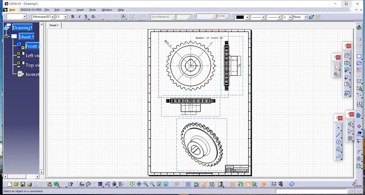
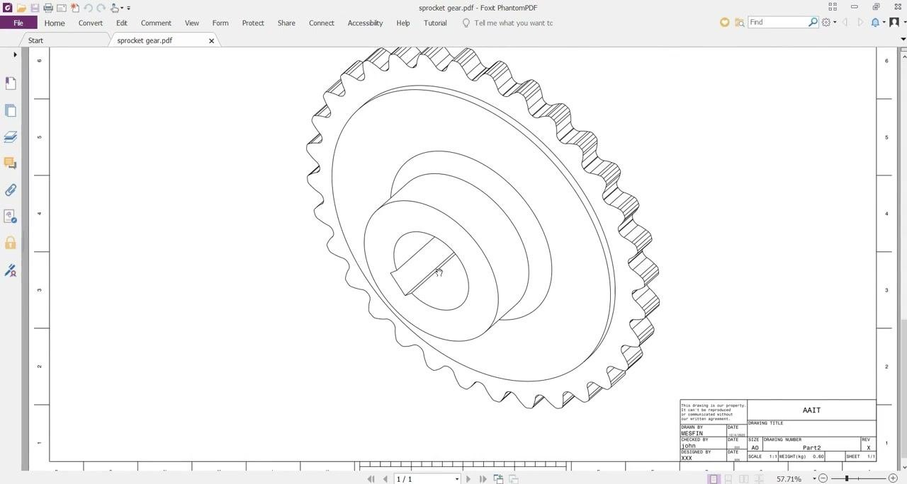
Open sprocket gear.pdf in your PDF viewer (for example, Foxit PhantomPDF) and inspect the drawing for clarity and completeness:
- Confirm the isometric view of the sprocket gear is clearly rendered, with all lines and features visible.
- Check the title block in the lower right corner for the drawing title, drawing number, revision, scale (1:1), sheet number (1/1), and the designer and checker names (for example, "DRAWN BY: MESFIN", "CHECKED BY: john", "DESIGNED BY: XXX").
- Check for additional notes such as "This drawing is our property..." and the organization label "AAIT".
- Ensure the drawing is centered and fits within the page margins.
- Verify that dimensions and annotations are present and legible.
Use the PDF viewer's zoom and navigation tools to examine all areas of the drawing. Confirm that the exported PDF matches the original CATIA V5 drawing in layout and detail.
Summary
You have now converted a 3D sprocket gear model to a 2D drawing in CATIA V5. You:
- Drafted a technical drawing in CATIA V5.
- Exported the drawing as a PDF file.
- Verified the exported PDF for accuracy, completeness, and professional presentation.
What's next
You can now share, print, or archive your technical drawing, knowing it meets documentation standards and preserves the critical design information.
Generation details: cost, quality tiers
Docsie billed 7,000 credits ($4.90) to analyze this 14-minute video at standard quality. The rewrite, template fill and Word/PDF exports were included. The same video at each quality tier:
| Quality | Frames sampled | Credits | Approx. cost |
|---|---|---|---|
| Draft | every 16-30 s | 3,500 | $2.45 |
| Standard (this guide) | every 8-15 s | 7,000 | $4.90 |
| Detailed | every 4-7 s | 14,000 | $9.80 |
| Ultra | every 1-3 s | 28,000 | $19.60 |
Credits priced at $0.70 per 1,000; plans include a monthly allowance. Enterprise customers on on-premise or bring-your-own-model deployments run this on their own inference and pay no per-video credits.
Generated by Docsie Video-to-Docs on 2026-11-15 from a 13-minute video. Screenshots are frames from the source video and belong to their creator, Mesfin Mamuye, whose original is embedded above. If you own this video and want the guide removed or credited differently, contact us and we will act within one business day.