
How to Do a Lockout Tagout Procedure (Ultra quality)
Before lockout tagout (LOTO) procedures existed, equipment often remained powered during repairs because there was no standardized or reliable way to secure it or communicate its operational status. Workers relied on verbal requests to operators, asking them not to start or energize equipment during maintenance, which left teams vulnerable to misunderstandings, accidental startups, and energy releases. This guide explains how to do a lockout tagout procedure using the eight-step structured process that replaced these informal, unsafe practices and now governs how hazardous energy is controlled during maintenance and repair work.
Video: Lockout Tagout Procedure - Control of Hazardous Energy by TRADESAFE (2025). All credit for the demonstration goes to the creator; watch the original on YouTube. The written guide below was generated from this video by Docsie. Creator? Request a change or removal.
Before lockout tagout (LOTO) procedures existed, equipment often remained powered during repairs because there was no standardized or reliable way to secure it or communicate its operational status. Workers relied on verbal requests to operators, asking them not to start or energize equipment during maintenance, which left teams vulnerable to misunderstandings, accidental startups, and energy releases. This guide explains how to do a lockout tagout procedure using the eight-step structured process that replaced these informal, unsafe practices and now governs how hazardous energy is controlled during maintenance and repair work.
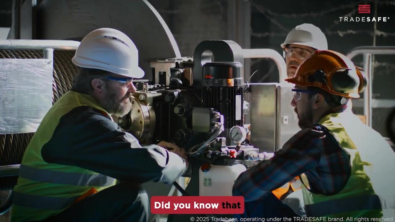
The eight-step lockout tagout procedure keeps everyone safe by systematically controlling energy sources through a clear, actionable sequence that can be applied consistently across a facility.
Scope
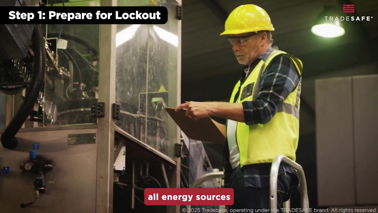
Before locking anything out, survey the equipment and its surrounding environment to determine every source of hazardous energy connected to it, using checklists or diagrams if they are available so no source is overlooked. This defines the boundaries of the job and the systems that will be affected once the lockout begins.
- Document each identified energy source for reference throughout the lockout process.
- Inform every employee who may be affected, including operators, maintenance staff, and supervisors, about which equipment will be locked out and why.
- Confirm that all affected personnel understand the plan before work proceeds.
A complete scope statement should also name the specific facility and the equipment tag number involved in the job; this level of site-specific identification is not part of the general procedure described here and should be added from your facility's own equipment records.
Energy sources
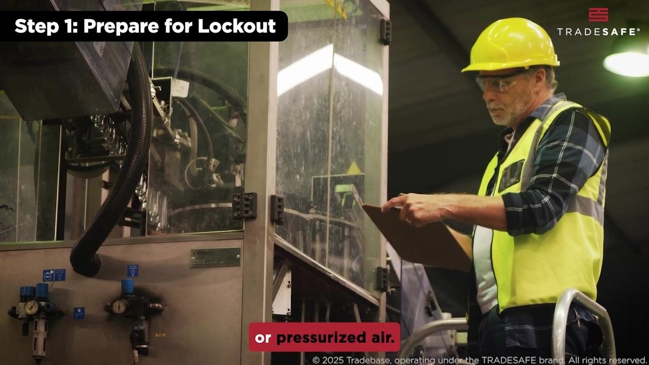
When you survey equipment, identify every type of energy that could pose a hazard. Include electrical power, hydraulic systems, and pressurized air, and inspect the machine carefully for hidden or secondary sources such as stored energy in springs or capacitors and backup power supplies.
- Electrical power connected to the equipment.
- Hydraulic systems and pressurized fluid lines.
- Pneumatic systems and pressurized air.
- Stored energy such as springs, capacitors, or residual pressure in tanks, pipes, and cylinders.
- Mechanical energy from parts that could move unexpectedly.
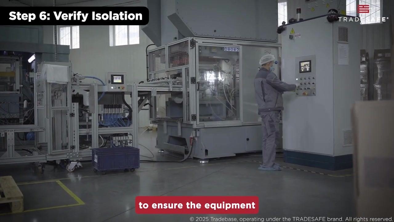
The source material does not separately address chemical, thermal, or gravity-related hazards; a complete energy source list for oil and gas equipment should also account for these where they apply on site.
Isolation points
Isolation points are the locations where energy is physically interrupted, such as circuit breakers, valves, and disconnect switches. Each point must be secured with a lockout device and a tag before work begins.
| Isolation point | Method used | Device applied |
|---|---|---|
| Circuit breaker / electrical panel switch | Flip the breaker or open the disconnect switch | Red lockout device on the switch |
| Valve on piping or a pressurized system | Close or turn the valve to stop flow | Lockout hasp secured to the valve |
| Disconnect switch | Disconnect the power supply | Lock and standardized "DANGER" tag |
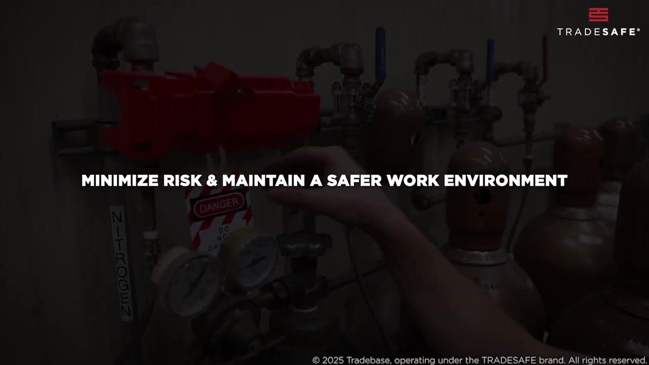
The procedure does not specify facility-specific tag numbers, blind or drain locations, or the named individual responsible for each isolation point; these details should be recorded on your site's own isolation point log before the lockout begins.
Lockout steps
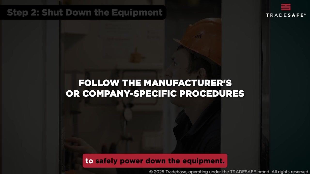
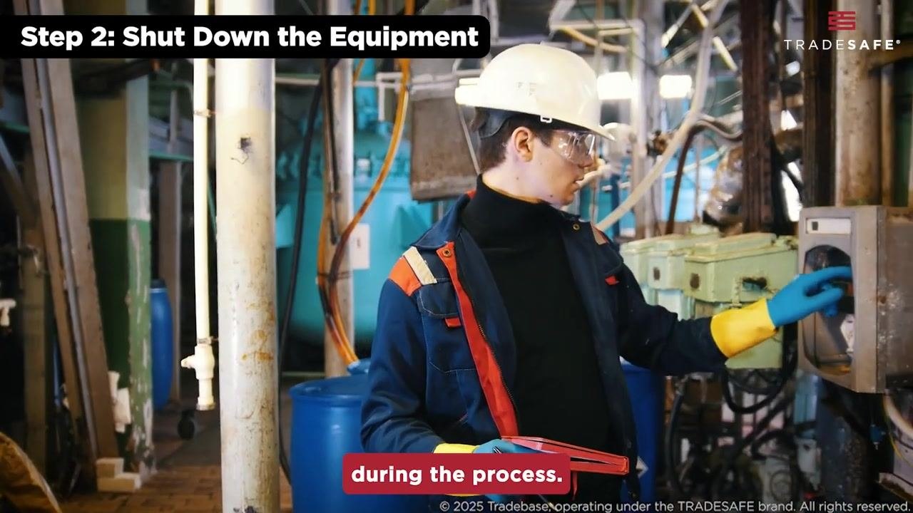
Follow the manufacturer's or company-specific procedures to safely power down the equipment before isolating it.
- Identify the correct shutdown sequence for the specific machine and use the control panel to press the appropriate buttons or switches to turn it off. Do not improvise or skip steps in the shutdown process.
- Ensure all moving parts have come to a complete stop, visually inspect the equipment, and listen for any sounds of operation before proceeding.
- Identify all energy isolation points, such as circuit breakers, valves, and disconnect switches, and flip, close, or disconnect them as required to isolate every form of hazardous energy.
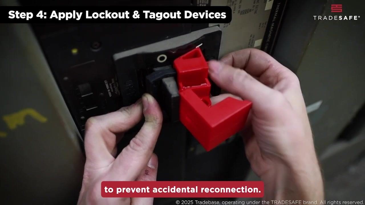
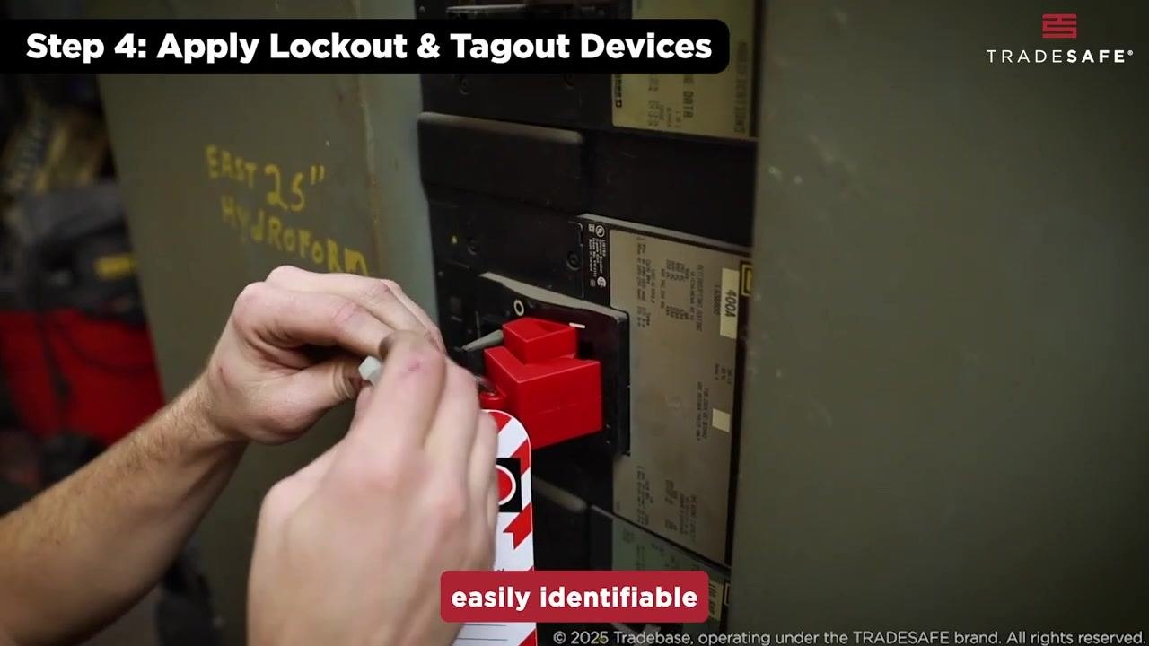
- Place a lockout device, such as a lock or hasp, on each energy isolation point so it cannot be reconnected without a key or tool.
- Attach a clearly labeled tag to each lockout device, filled out with the name of the person applying the lock and the reason for the lockout, using standardized tags that include a DANGER warning and space for remarks.
- Use OSHA-standardized locks and tags so they are easily identifiable to everyone on site, and double-check that each isolation point is locked and tagged before proceeding.
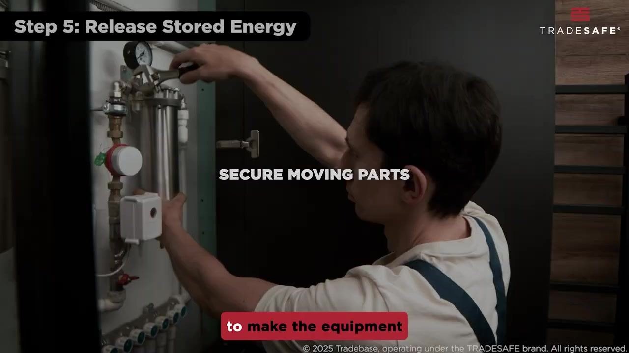
- Release any residual pressure from the system by opening valves or using bleed devices to safely vent trapped pressure from tanks, pipes, or cylinders, and bleed off hydraulic fluid as necessary.
- Secure all moving parts using blocks, pins, or restraints so no part of the equipment can move unexpectedly.
- Communicate the lockout status to all affected employees so everyone understands which equipment is locked out and why.
Zero-energy verification
Once every isolation point is locked and tagged, test the controls to confirm the equipment is completely de-energized before maintenance begins.
- Attempt to restart the machine using its normal controls and confirm it does not power on or operate.
- Double-check that all lockout/tagout devices remain in place and that all energy sources are isolated and released.
- Observe all indicator lights and gauges for any sign of residual energy, such as illuminated lights or pressure gauges reading above zero.
- Only proceed with maintenance once every indicator confirms the equipment is in a zero-energy state.
The source procedure does not describe separate voltage testing with a meter or gas testing instruments; where those checks apply to your equipment, add them to this verification step along with a record of the results.
Shift handover
The source material does not describe a shift handover process. A complete procedure should state how personal locks are transferred between shifts, whether a group lock box is used, how permit continuity is maintained, and what checks a supervisor performs before work resumes.
Restoration
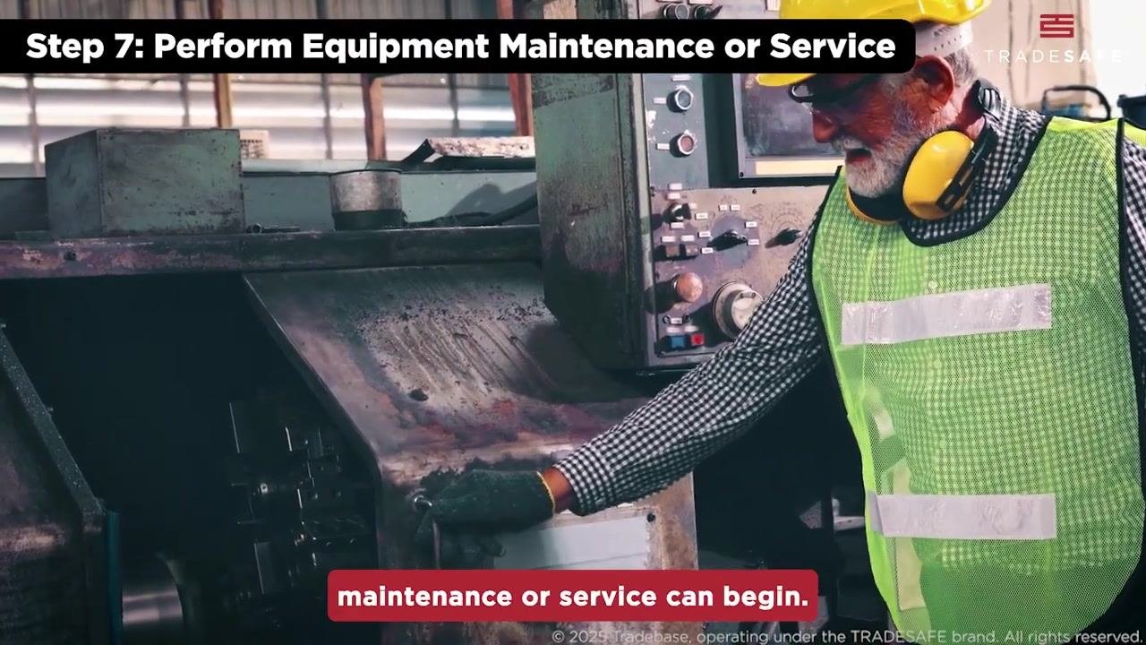
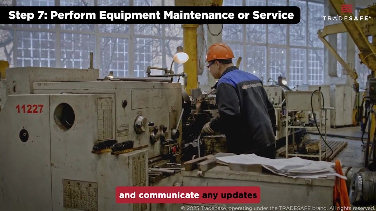
Maintenance or service work begins only after isolation has been verified, and it must follow the outlined procedures for the specific task, using all tools and materials correctly as specified in the work instructions. Do not remove any lockout/tagout devices while work is underway, and communicate any updates or changes in status with the team until all tasks are finished and the area is clear of tools and materials.
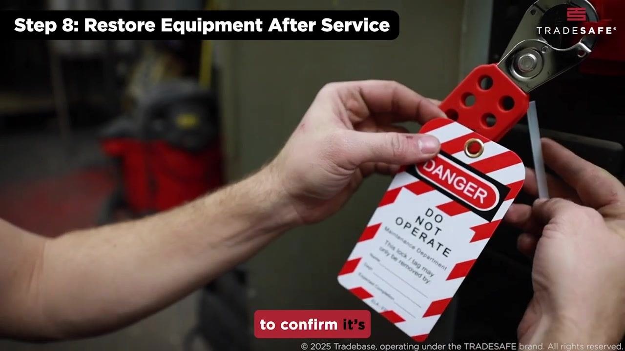
Once maintenance is complete, restore the equipment to operational status by following these steps:
- Confirm the identity of the employee removing each device: only the person who applied a lockout or tagout device is permitted to remove it.
- Carefully detach the lockout hasp and DANGER DO NOT OPERATE tag from each isolation point.
- Inspect the area to ensure all tools and personnel are clear before restoring power.
- Reconnect all previously isolated energy sources, including electrical, hydraulic, and pneumatic systems, in the correct sequence.
- Test the equipment to confirm it is functioning properly and safely before returning it to service.
Refer to your lockout/tagout checklist to confirm no steps were missed and to double-check all isolation points and documentation before declaring the equipment safe for use.
What's next
Lockout/tagout remains a reliable method for controlling hazardous energy and minimizing risk, and following established procedures consistently protects both workers and equipment. Share lockout/tagout safety tips with your team and continue to refer to your company's LOTO checklist and resources for complete compliance and continuous improvement.


Generation details: cost, quality tiers, downloads
Docsie billed 8,000 credits ($5.60) to analyze this 4-minute video at ultra quality. The rewrite, template fill and Word/PDF exports were included. The same video at each quality tier:
| Quality | Frames sampled | Credits | Approx. cost |
|---|---|---|---|
| Draft | every 16-30 s | 1,000 | $0.70 |
| Standard | every 8-15 s | 2,000 | $1.40 |
| Detailed | every 4-7 s | 4,000 | $2.80 |
| Ultra (this guide) | every 1-3 s | 8,000 | $5.60 |
Credits priced at $0.70 per 1,000; plans include a monthly allowance. Enterprise customers on on-premise or bring-your-own-model deployments run this on their own inference and pay no per-video credits.
Same video, other quality tiers
We ran this exact video through Docsie again at different frame-sampling rates. Compare the guides side by side:
| Quality | Frame every | Screenshots | Credits | Cost |
|---|---|---|---|---|
| Ultra (this guide) | 1 s | 16 | 8,000 | $5.60 |
| Standard | 8-15 s | 8 | 2,000 | $1.40 |
Generated by Docsie Video-to-Docs on 2026-09-10 from a 3-minute video. It was generated straight into Docsie's Lockout Tagout Procedure template, so every section of that template is filled from the video. Screenshots are frames from the source video and belong to their creator, TRADESAFE, whose original is embedded above. If you own this video and want the guide removed or credited differently, contact us and we will act within one business day.