
How to Calculate an Arc Flash Boundary
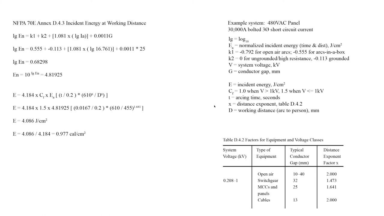
This procedure describes how to calculate an arc flash boundary by first determining the incident energy of an arc flash event using the NFPA 70E Annex D.4.3 formula. The calculation builds on a previously determined arcing current and produces the incident energy value, expressed in cal/cm², that is used for PPE hazard category selection and arc flash boundary determination on equipment labels.
Video: Calculate incident energy of arc flash - NFPA 70E by Jonathan Gracey (2018). All credit for the demonstration goes to the creator; watch the original on YouTube. The written guide below was generated from this video by Docsie. Creator? Request a change or removal.
This procedure describes how to calculate an arc flash boundary by first determining the incident energy of an arc flash event using the NFPA 70E Annex D.4.3 formula. The calculation builds on a previously determined arcing current and produces the incident energy value, expressed in cal/cm², that is used for PPE hazard category selection and arc flash boundary determination on equipment labels.
Purpose
This SOP walks you through the NFPA 70E Annex D.4.3 method for calculating incident energy, from the basic formula through the final conversion to cal/cm². Completing this calculation is a required step in determining the PPE hazard category and supporting the arc flash boundary calculation for a piece of electrical equipment.
Scope
This procedure applies to incident energy calculations for equipment such as motor control centers (MCCs) and panel boards in the 0.208–1 kV class, and can be adapted for other equipment types, including switchgear, and for both grounded and ungrounded (high-resistance) systems.
Requirements
Before starting, confirm you have the following information available:
- The previously calculated arcing current (Ia) for the system.
- The system voltage and the bolted three-phase short circuit current.
- The NFPA 70E Annex D.4.3 formulas and the constants k1 and k2 for your arc type and grounding configuration.
- Table D.4.2, for the conductor gap and distance exponent values.
- The manufacturer's time-current curve for the overcurrent protective device (fuse or circuit breaker).
- The working distance (D) specified for the equipment.
Steps
Review the calculation objective
Confirm that your objective is to calculate the incident energy for an arc flash event, continuing from a previously calculated arcing current. This calculation follows NFPA 70E, Annex D.4.3, section D.3, for incident energy.
Review the basic incident energy formula
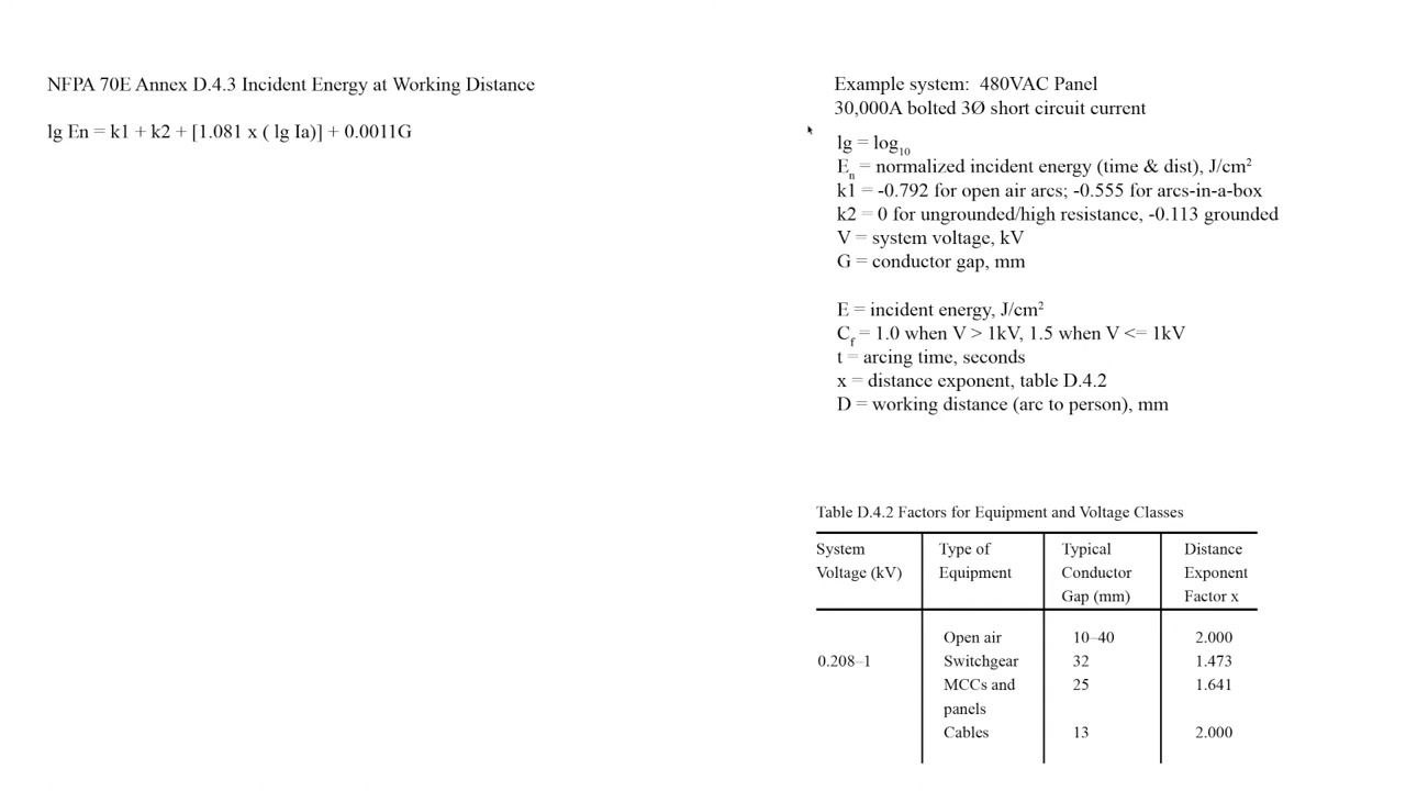
Refer to the basic formula for normalized incident energy at working distance:
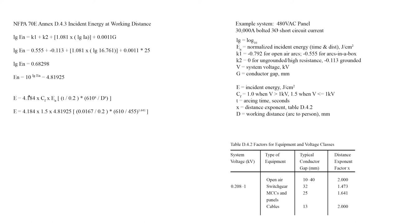
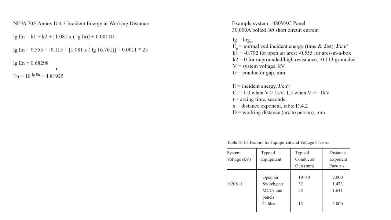
lg En = k1 + k2 + [1.081 × (lg Ia)] + 0.0011G
lgdenotes log base 10.Enis the normalized incident energy (J/cm²).Iais the arcing current (previously calculated).Gis the conductor gap in millimeters.k1andk2are constants based on arc type and system grounding.
Identify your system parameters and reference Table D.4.2
For this example, the system is a 480VAC Panel with a bolted three-phase short circuit current of 30,000A. Use the following constants and variables:
k1 = -0.792for open air arcs, or-0.555for arcs-in-a-box (use-0.555for a panel board).k2 = 0for ungrounded/high-resistance systems, or-0.113for grounded systems (use-0.113for this grounded system).G = 25 mm, the typical conductor gap for panel boards.Ia = 16 kA, the previously calculated arcing current.
Reference Table D.4.2 for the conductor gap and distance exponent: for MCCs and panels, the typical conductor gap is 25 mm and the distance exponent is 1.641.
Substitute values into the formula
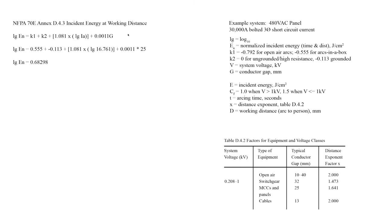
Substitute the constants and calculated values into the formula:
lg En = -0.555 + (-0.113) + [1.081 × (lg 16.761)] + 0.0011 × 25
Calculate each term step by step:
lg 16.761 ≈ 1.2241.081 × 1.224 ≈ 1.3230.0011 × 25 = 0.0275- Sum:
-0.555 + (-0.113) + 1.323 + 0.0275 ≈ 0.68298
The result is lg En = 0.68298.
Calculate the normalized incident energy
Remove the logarithm by raising 10 to the calculated power:
En = 10^(0.68298) ≈ 4.81925 J/cm²
This is the normalized incident energy at the working distance for the given system parameters.
Apply the full incident energy formula
The value calculated in the previous step is the normalized incident energy, not the actual incident energy at the working distance. To find the actual incident energy (E), use the full formula:
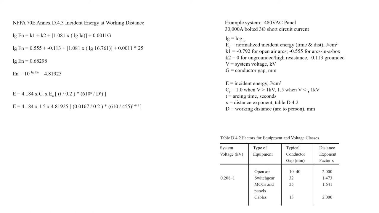
E = 4.184 × Cf × En × [(t / 0.2) × (610^x / D^x)]
E= incident energy (J/cm²)Cf= constant factor (1.0 if V > 1kV, 1.5 if V ≤ 1kV)En= normalized incident energy (J/cm²)t= arcing time (seconds)x= distance exponent (from Table D.4.2)D= working distance (mm)
Example substitution:
E = 4.184 × 1.5 × 4.81925 × [(0.0167 / 0.2) × (610 / 455)^1.641]
Select the correct constant factor (Cf)
Choose the constant factor based on system voltage:
- For systems with voltage ≤ 1kV, use
Cf = 1.5. - For systems with voltage > 1kV, use
Cf = 1.0.
In this example, the system voltage is 480V, so set Cf = 1.5.
Determine the arcing time (t)
The arcing time (t) is determined by the time-current characteristic of your overcurrent protection device (fuse or circuit breaker).
Safety note: Do not use the bolted three-phase fault current for this calculation. Always use the arcing current (previously calculated as 16.7 kA) to find the trip time from the manufacturer's time-current curve, since the bolted fault current does not represent arc flash conditions. In this example, the trip time for 16.7 kA is 0.0167 seconds, so use t = 0.0167.
Reference the distance exponent and working distance
Use Table D.4.2 to find the distance exponent (x) for your equipment type and voltage class. For a 480V panel (MCCs and panels, 0.208–1 kV):
- Typical conductor gap: 25 mm
- Distance exponent: 1.641
Use the working distance (D) specified for your system (in this example, 455 mm).
Substitute all values and calculate the incident energy
Substitute all determined values into the formula:
Cf = 1.5En = 4.81925t = 0.0167secondsx = 1.641D = 455mm
The formula becomes:
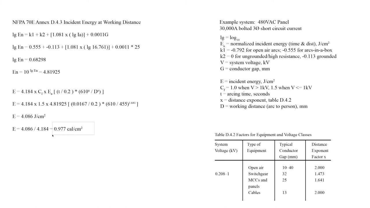
E = 4.184 × 1.5 × 4.81925 × [(0.0167 / 0.2) × (610 / 455)^1.641]
Performing this calculation gives a result of E = 4.086 J/cm².
Convert incident energy to calories per square centimeter
Convert the result from joules to calories using the conversion factor 1 cal = 4.184 J:
E = 4.086 J/cm² ÷ 4.184 = 0.977 cal/cm²
This cal/cm² value is what you use to determine the hazard risk category for PPE selection and to support the arc flash boundary determination for the equipment label.
Confirm unit conversion and methodology flexibility
Always convert your final incident energy value to cal/cm², since this is the standard unit referenced in arc flash labeling and PPE requirements.
Note that the NFPA 70E Annex D.4.3 formulas and the previously calculated arcing current allow you to mix and match variables to fit your system:
- Adapt the constants for grounded or ungrounded systems.
- Apply the method to different equipment types, such as switchgear or panel boards.
- Adjust the conductor gap, distance exponent, and working distance for your specific equipment.
This approach is customizable across system configurations, which makes it a reliable choice for calculating incident energy. Other calculation methods are also available in NFPA 70E Annex D.4, and you may select whichever method best fits your system and needs.
Verification and summary
Confirm that you have completed the following before finalizing your arc flash label or safety analysis:
- Identified the correct formula and constants for your system (arc type, grounding, conductor gap).
- Substituted the arcing current and other values into the normalized incident energy formula.
- Calculated the log of the normalized incident energy and converted it to
En. - Applied the full incident energy formula with the correct constant factor (Cf), arcing time (t), distance exponent (x), and working distance (D).
- Determined arcing time from the arcing current and the manufacturer's time-current curve, not the bolted fault current.
- Calculated the final incident energy in J/cm² and converted it to cal/cm² for PPE hazard category determination.
Additional reference screenshots for the full formula and final calculation:
By following these steps, you can accurately determine the incident energy for arc flash labeling and safety analysis using NFPA 70E Annex D.4.3, which supports correct PPE selection and arc flash boundary determination for your equipment.
Generation details: cost, quality tiers
Docsie billed 2,500 credits ($1.75) to analyze this 5-minute video at standard quality. The rewrite, template fill and Word/PDF exports were included. The same video at each quality tier:
| Quality | Frames sampled | Credits | Approx. cost |
|---|---|---|---|
| Draft | every 16-30 s | 1,250 | $0.88 |
| Standard (this guide) | every 8-15 s | 2,500 | $1.75 |
| Detailed | every 4-7 s | 5,000 | $3.50 |
| Ultra | every 1-3 s | 10,000 | $7.00 |
Credits priced at $0.70 per 1,000; plans include a monthly allowance. Enterprise customers on on-premise or bring-your-own-model deployments run this on their own inference and pay no per-video credits.
Generated by Docsie Video-to-Docs on 2026-09-14 from a 4-minute video. Screenshots are frames from the source video and belong to their creator, Jonathan Gracey, whose original is embedded above. If you own this video and want the guide removed or credited differently, contact us and we will act within one business day.