
How to Welding Aluminium
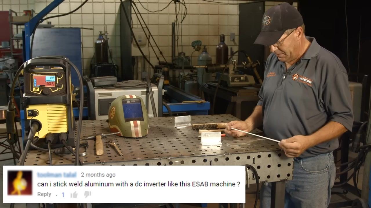
This procedure explains how to weld aluminum using the stick (SMAW) process on a DC inverter machine such as an ESAB EMP 210. Stick welding aluminum is less common than TIG or wire feed processes, which produce cleaner results and are generally preferred, but it is entirely possible when a DC inverter is set up correctly. This guide covers polarity settings, preheating, cleaning, electrode setup, welding technique, and evaluation of the finished weld — useful for field repairs such as handrails or broken aluminum equipment when a TIG or spool gun setup isn't available.
Video: Stick Welding Aluminum by Weld.com (2016). All credit for the demonstration goes to the creator; watch the original on YouTube. The written guide below was generated from this video by Docsie. Creator? Request a change or removal.
This procedure explains how to weld aluminum using the stick (SMAW) process on a DC inverter machine such as an ESAB EMP 210. Stick welding aluminum is less common than TIG or wire feed processes, which produce cleaner results and are generally preferred, but it is entirely possible when a DC inverter is set up correctly. This guide covers polarity settings, preheating, cleaning, electrode setup, welding technique, and evaluation of the finished weld — useful for field repairs such as handrails or broken aluminum equipment when a TIG or spool gun setup isn't available.
Purpose
This document provides step-by-step instructions for stick welding aluminum with a DC inverter machine, including preheating methods, machine settings, cleaning techniques, and weld evaluation, so that field repairs can be completed even without access to TIG or wire welding equipment.
Scope
This procedure applies to fillet welds on quarter-inch aluminum stock using a low hydrogen electrode on a DC inverter welding machine. It covers preparation, preheating, welding, and post-weld cleanup and inspection.
Required equipment and PPE
- DC inverter welding machine capable of DC electrode positive (DCEP) output, such as an ESAB EMP 210
- 3/32" (2.4 mm) low hydrogen electrode suitable for aluminum
- Aluminum workpieces (quarter-inch thickness used in this procedure)
- Oxy-acetylene torch
- Temperature-indicating stick (Tempilstik), ideally rated for 350°F (a 250°F stick can be substituted if that is all you have)
- Stainless steel wire brush (dedicated to aluminum only)
- Chipping hammer
- Needle-nose pliers
- Marker
- Welding helmet
- Welding jacket and gloves
- Safety glasses
Procedure
Confirm setup and polarity
1. Confirm that stick welding aluminum is possible. Stick welding aluminum with a DC inverter machine is achievable, though TIG and wire welding processes are cleaner and typically preferred for aluminum work.
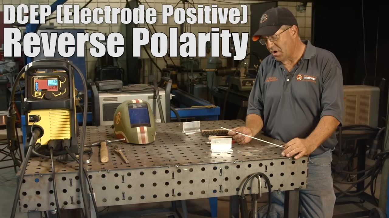
2. Set the machine to DC electrode positive (DCEP). Aluminum stick welding requires DC reverse polarity (DCEP: Electrode Positive). This setting is critical for correct arc characteristics and weld quality.
Safety/quality note: Confirm polarity before striking an arc — incorrect polarity will produce a poor arc and unusable weld on aluminum.
3. Prepare the workpieces. This demonstration uses quarter-inch aluminum material to perform a couple of fillet welds (front and back). Expect the second weld to come out better than the first, since the material will already be preheated from the first pass.
4. Understand why preheating matters. Preheat the aluminum workpieces before welding. Attempting to weld cold aluminum will produce poor results. Warm the material briefly before starting the actual weld.
5. Understand the nature of aluminum stick welding. The process is "gummy" and produces a heavy, salty flux that turns into gray, spattery muck as it burns. This is normal, even if it looks unusual if you haven't done it before.
6. Recognize alloy variability. There are many maintenance alloys available for aluminum stick welding. Some run better than others, similar to the variability seen with stainless and low hydrogen electrodes.
Preheating the aluminum
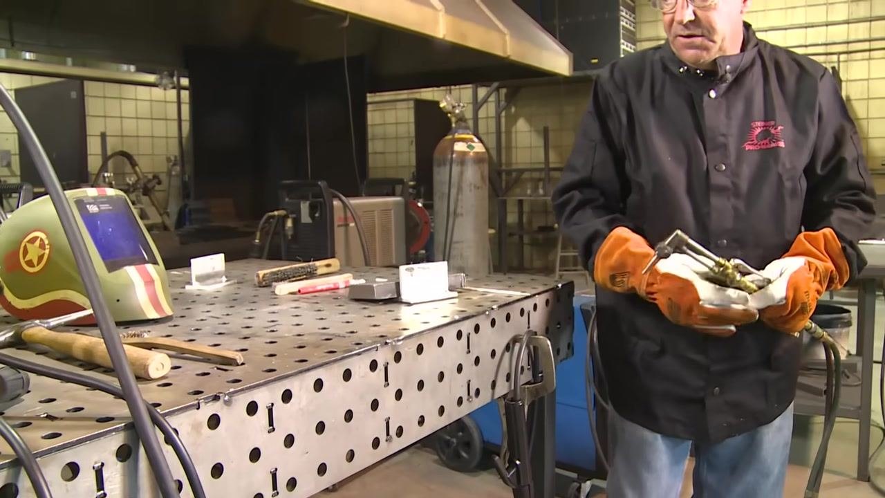
7. Gather the preheating equipment. Before preheating, confirm you have an oxy-acetylene torch, welding helmet, wire brush, marker, quarter-inch aluminum workpieces, and a temperature-indicating stick (Tempilstik) — ideally rated for 350°F, though a 250°F stick will work if that's all you have. Confirm your welding machine is set up and ready.
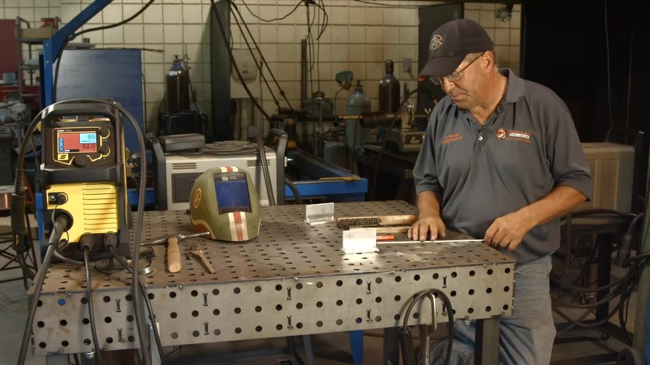
8. Choose your temperature indicator method. If a 350°F Tempilstik is not available, use a 250°F stick or the soot trick instead. The soot trick uses a carburizing flame to deposit soot on the aluminum; when the soot burns off, the metal is at approximately 400°F.
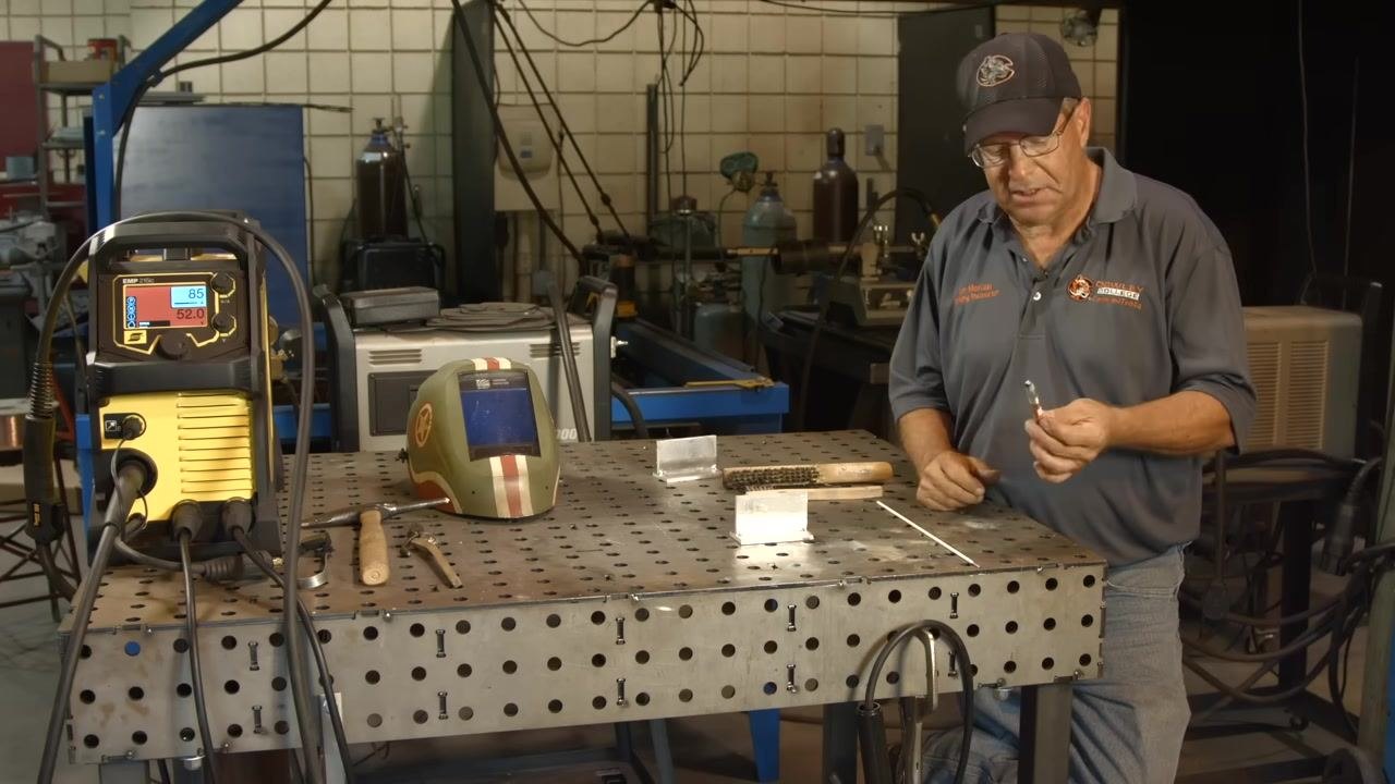
9. Apply the Tempilstik to the workpiece. Use the Tempilstik to mark the aluminum. When the mark melts, the metal has reached the indicated temperature. This procedure demonstrates with a 250°F stick, since a 350°F stick wasn't available.
10. Mark the aluminum workpiece. Apply the Tempilstik to the aluminum to check its temperature as preheating proceeds.
11. Set the torch to a carburizing flame. Light the oxy-acetylene torch and adjust it to a carburizing flame (excess unburnt acetylene/fuel) to produce a sooty, black flame.
12. Apply soot to the aluminum. Pass the carburizing flame over the aluminum workpiece to deposit a layer of black soot, which serves as a visual temperature indicator.
13. Heat the aluminum until the soot disappears. After applying soot, switch the torch to a neutral flame and continue heating until the soot disappears. This indicates the metal is around 400°F, suitable for welding.
Safety note: Do not overheat the workpiece — apply just enough heat to saturate it for good weld flow.
14. Confirm readiness to weld. Once the aluminum is preheated and the soot has disappeared, you are ready to begin welding. Keep the heat moderate — just enough to ensure proper weld flow, without going to extremes.
15. Switch to a neutral flame for further preheating. Adjust the oxy-acetylene torch from a carburizing flame to a neutral flame and hold the torch further from the workpiece to continue the preheating process. Wear protective gloves and a welding jacket throughout.
16. Begin preheating with the neutral flame. Direct the neutral flame onto the aluminum workpiece to gradually raise its temperature, moving the torch evenly to avoid overheating any one area.
17. Monitor temperature with the Tempilstik. Touch a 250°F Tempilstik to the workpiece periodically during heating. When the mark melts, the workpiece has reached 250°F. As the temperature approaches the mark: "We're not quite to 250, and now we are."
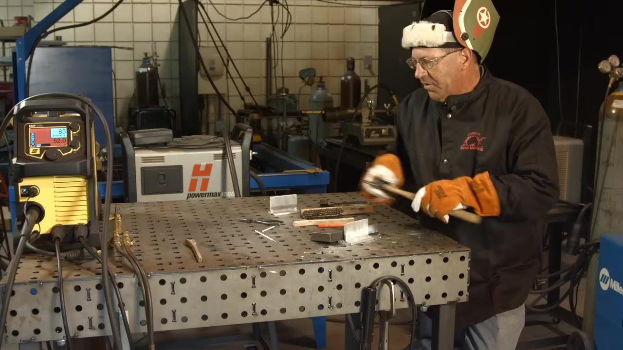
18. Account for aluminum's rapid heat loss. Aluminum dissipates heat about four times faster than carbon steel. Maintain consistent heat application to keep the workpiece at the desired temperature.
19. Clean the aluminum properly. Always pre-clean aluminum with stainless steel wire brushes before welding. Avoid grinding wheels or wire wheels previously used on carbon steel, as they can embed contaminants and fold the oxide layer into the aluminum. Light sanding, chemical etching, or hand wire brushing are the best cleaning methods.
Safety/quality note: Cross-contamination from carbon steel tools is a common cause of poor aluminum welds.
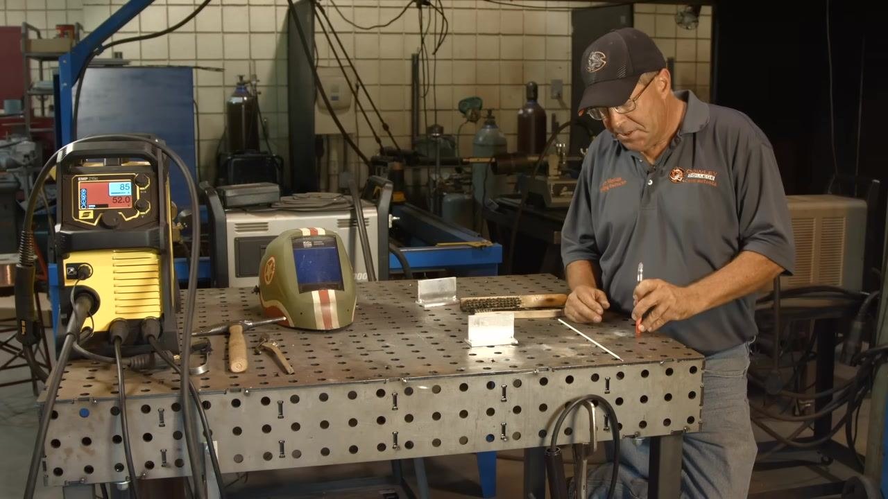
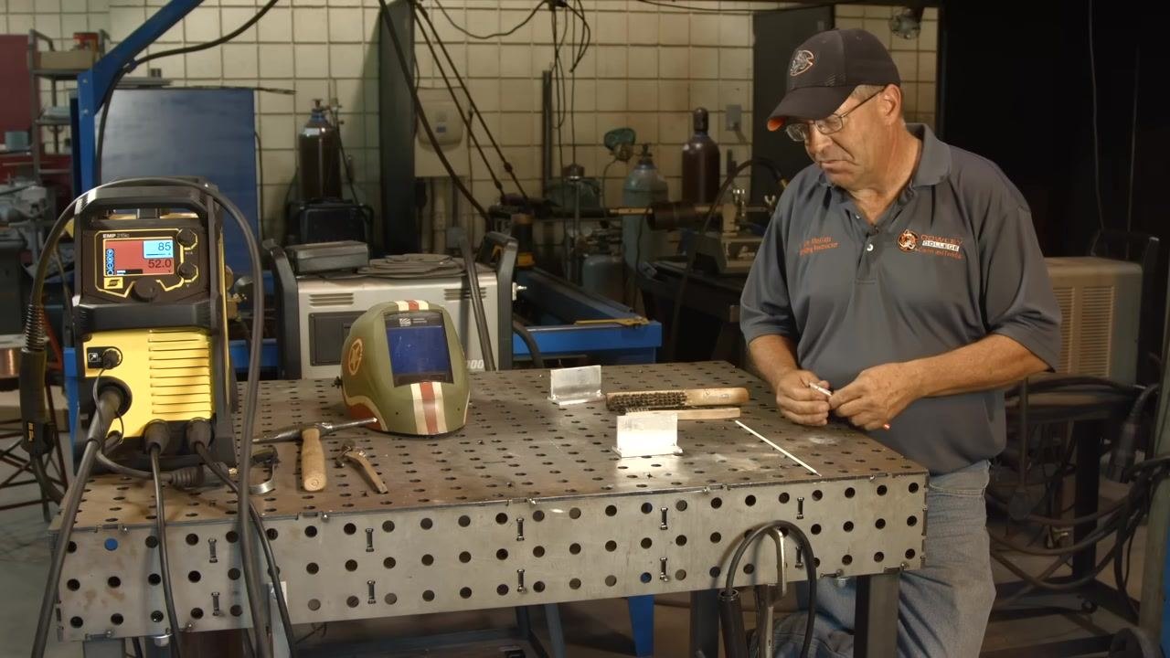
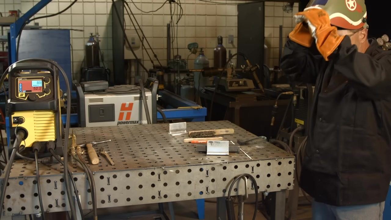
20. Set up the electrode and machine parameters. Use a 3/32" (2.4 mm) electrode for stick welding aluminum. Set the welding machine to 85 amps and 52.0 volts, and confirm it is set to DC electrode positive (reverse polarity).
21. Put on PPE and stage the work area. Put on your welding helmet and confirm all safety gear is in place. Verify the work area is clear and all tools are within reach before striking an arc.
Welding the first joint
22. Understand the challenge of low hydrogen electrodes. Low hydrogen electrodes are more difficult to run than other electrode types because of the flux coating on the tip — expect them to be roughly three times more challenging.
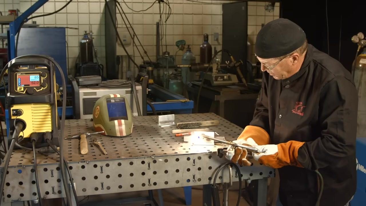
23. Prepare the welding area and equipment. Clear the welding table except for a wire brush, chipping hammer, pencil, and the metal workpieces. Confirm the machine is powered on and set to the correct parameters (85A, 52.0V). Wear a welding jacket, gloves, and helmet. Hold the electrode holder in your dominant hand and the electrode in the other, ready for setup.
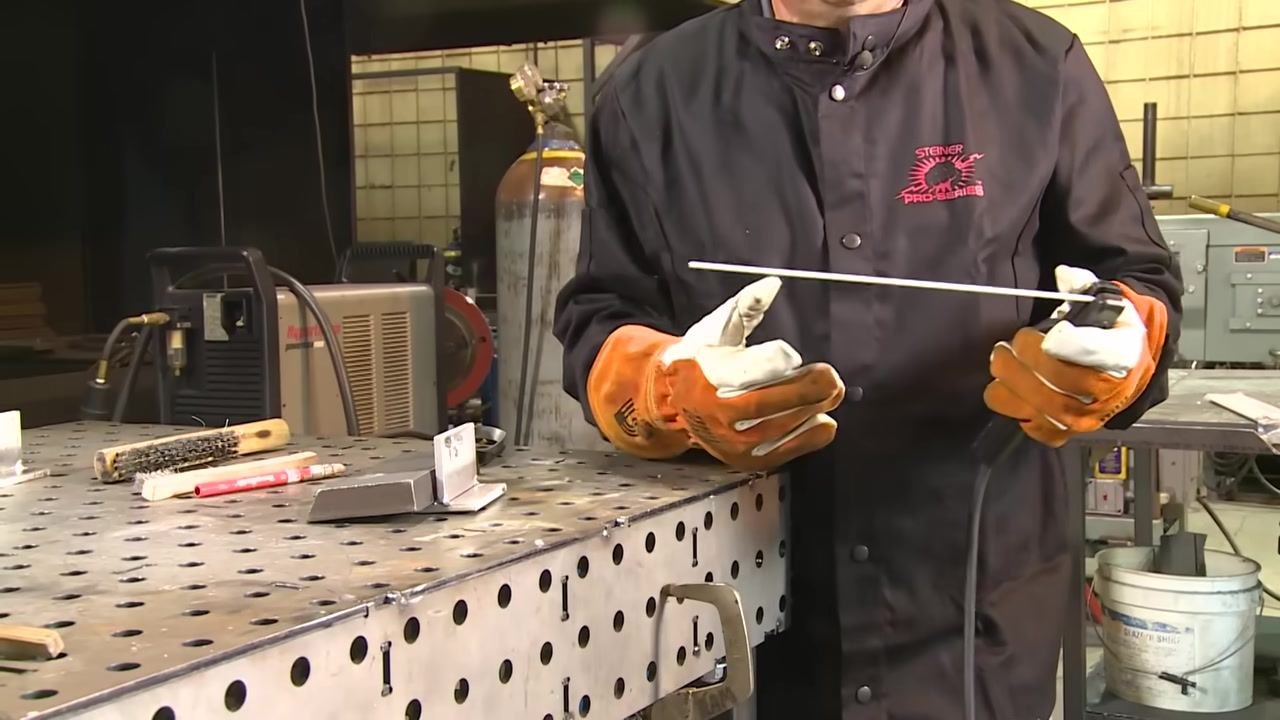
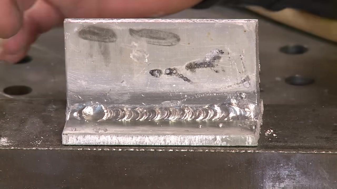
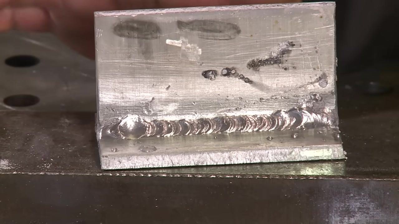
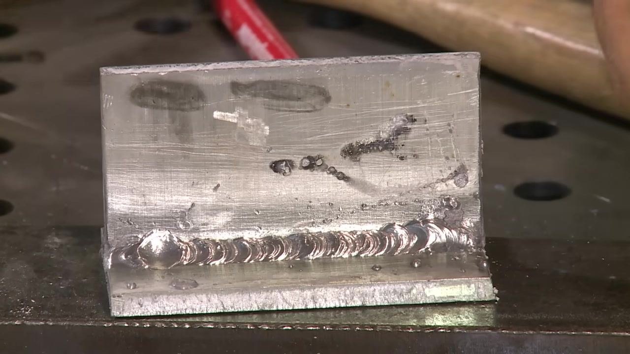
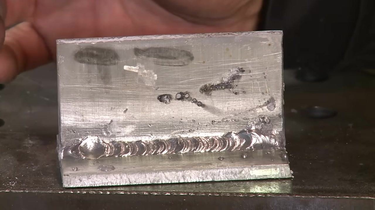
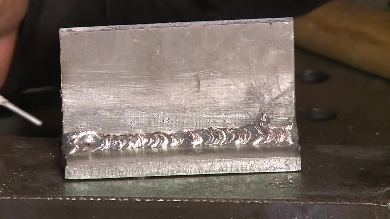
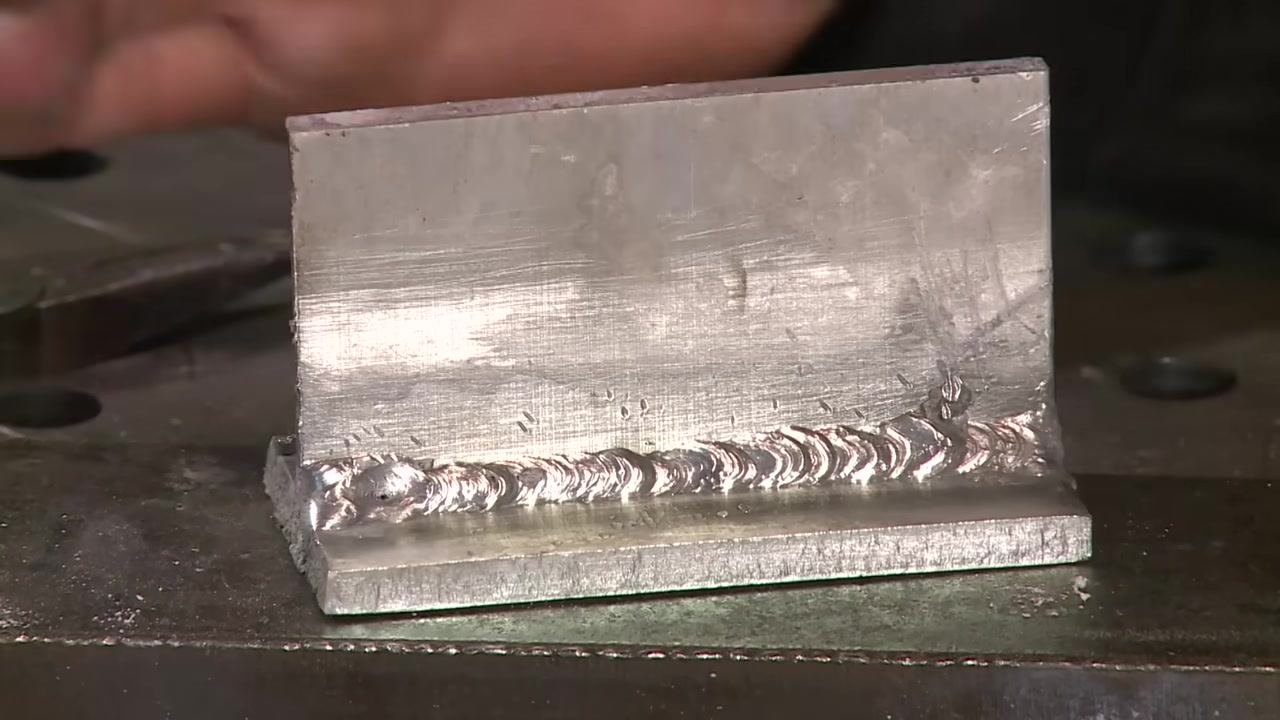
24. Position the electrode for welding. Hold the electrode at a straight end angle. Use a fast travel speed, as recommended for low hydrogen electrodes. Position the electrode near the joint, ensuring proper alignment.
25. Inspect the weld joint before welding. Examine the metal pieces to be joined, ensuring they are clean and properly aligned. Note any tack welds or initial weld beads already present on the joint.
26. Note the field-repair context. This technique is applicable to repairs such as handrails or broken equipment in the field, away from the shop.
27. Begin the first weld pass. Initiate the arc and weld along the joint, maintaining a straight angle and fast travel speed. Watch the machine display for real-time amperage and voltage (example: 87A, 19.2V), and monitor the arc and weld pool closely for consistency.
28. Evaluate the initial weld. After completing the first pass, expect some difficulty or a rough start. Allow the welded joint to cool slightly before proceeding.
29. Prepare for the second weld pass. Plan to weld the backside of the joint using a new electrode. If necessary, remove flux from the tip of the new electrode with needle-nose pliers to ensure a clean start.
30. Pause and let the joint cool. Let the joint cool before handling it further. Keep safety gear on and maintain a clean, organized workspace.
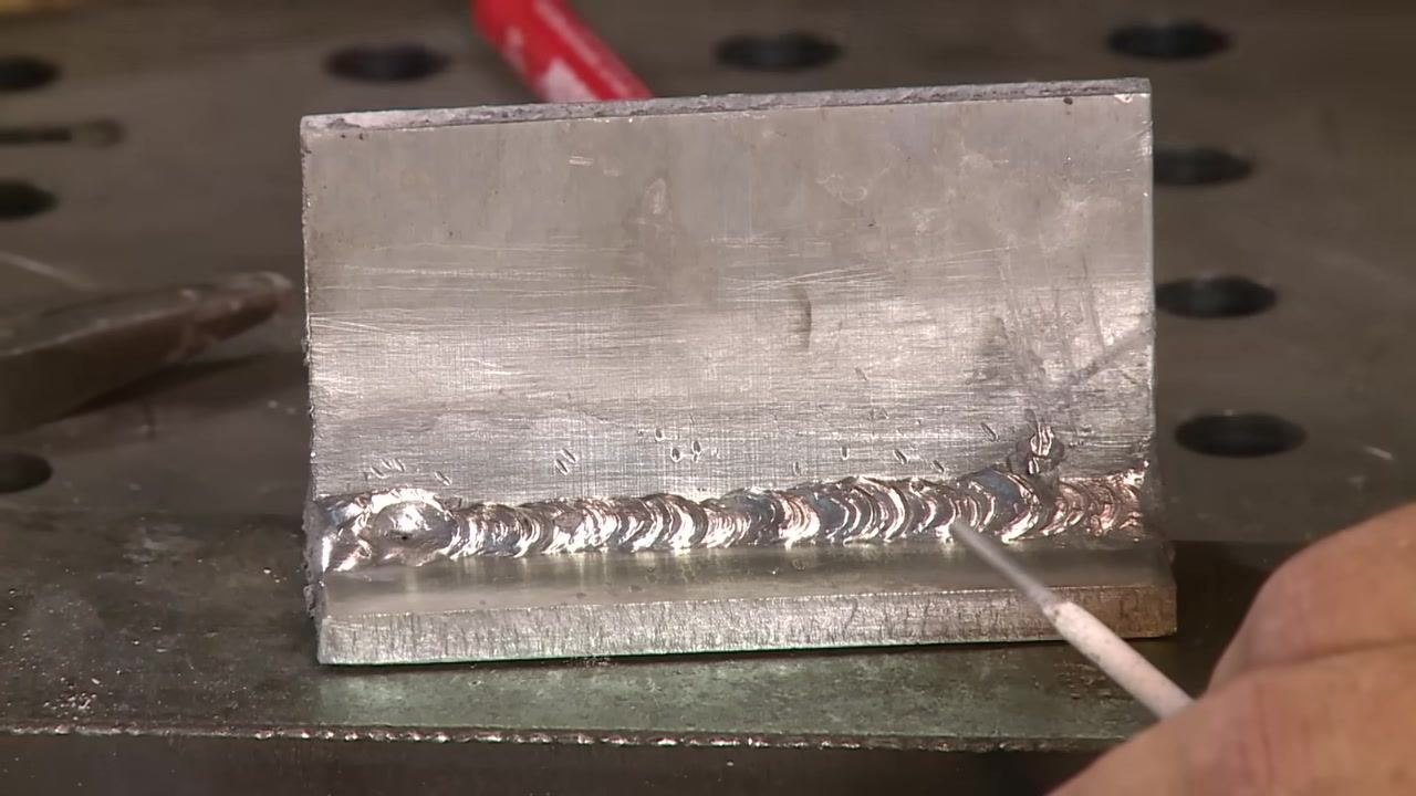
Cleaning and evaluating the first weld
31. Inspect the weld for inconsistencies. Look closely at the welded joint, focusing on the area roughly halfway to two-thirds along the weld bead. Note any irregularities, such as changes in bead shape or surface texture, using a chipping hammer or pliers to point out or manipulate the weld area as needed.
32. Remove spatter from the weld. Use pliers or a chipping hammer to remove spatter from and around the welded area. Keep the workspace clean to protect weld quality and safety.
33. Assess the previous pass before improving the next. Review the previous weld start and plan improvements for the next attempt. Confirm the electrode is properly positioned and the work area is clear of excess slag or debris.
34. Set up for the next weld pass. Stand at the welding table with tools and materials within reach. Hold the electrode holder in your dominant hand and a new electrode in the other. Confirm the machine is set to 85A/52.0V and wear all required PPE, with the helmet raised while preparing.
35. Note grinding and multi-pass guidance. "With light pressure, grind and blend this back. You can do multiple passes." After welding, use a grinder with light pressure to blend the weld bead, and plan for additional passes if needed to achieve the desired joint strength and appearance.
Welding the second pass
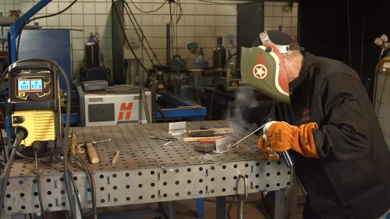
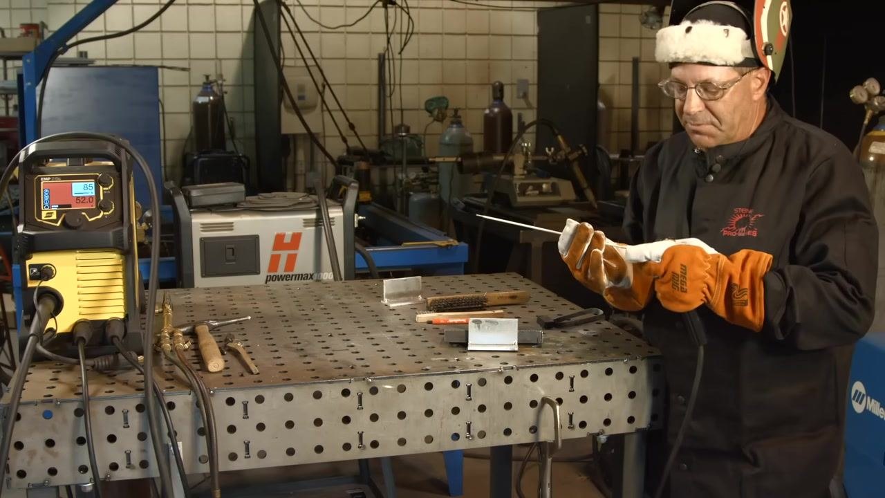
36. Perform the next weld pass. Lower the welding helmet and initiate the arc on the prepared joint, maintaining proper electrode angle and travel speed for a consistent bead. Monitor the machine display for real-time amperage (101A) and voltage (17.5V), and follow all safety protocols during active welding.
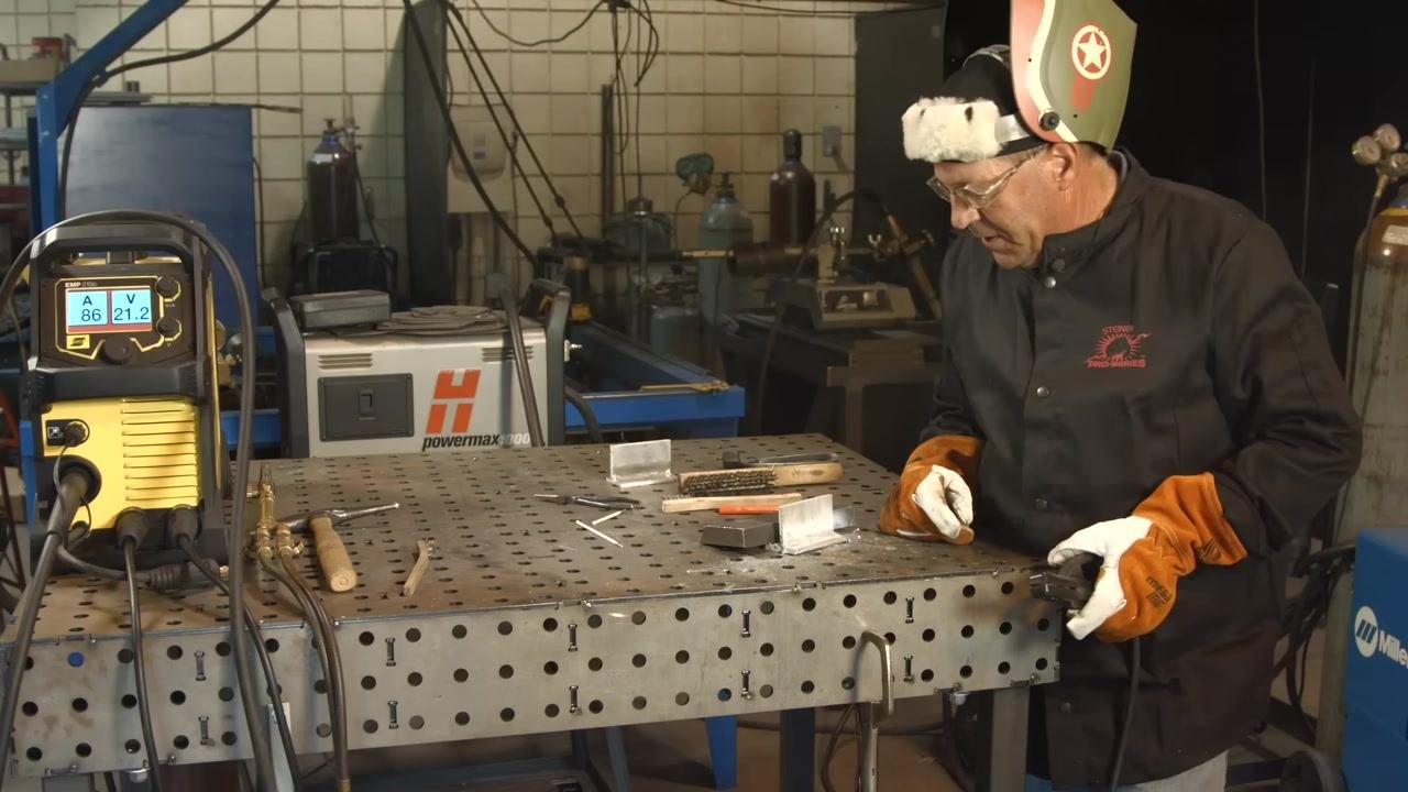
37. Monitor the welding process. Watch the arc and weld pool, adjusting technique as needed for bead consistency. The machine display may fluctuate (example: 86A, 20.2V) during the process. Keep the workspace organized and free of unnecessary clutter.
38. Evaluate the weld outcome. After completing the pass, raise the helmet and inspect the joint. Note any issues, such as craters or washed-out areas in the bead — such results can occur and are worth acknowledging.
39. Examine the weld crater. Closely inspect the end of the weld bead for signs of a crater or washed-out area. Identify any defects that may require additional passes or grinding to correct.
40. Consider how base-metal softness affects the ripple pattern. "Because I think the aluminum is so soft, it will just rearrange the whole ripple pattern." The softness of aluminum as a base material can affect the weld bead's appearance and structure — plan to adjust technique or perform additional passes to achieve the desired ripple pattern and weld quality.
Evaluating and cleaning the completed welds
41. Assess the effect of base material softness. Standing at the perforated metal welding table in a welding jacket, gloves, and raised helmet, confirm the welding machine (EMP 215ic) is set to 85A and 52.0V. Tools on the table include a wire brush, chipping hammer, pliers, metal workpieces, and a red marker, in a workshop environment with gas cylinders and other equipment nearby.
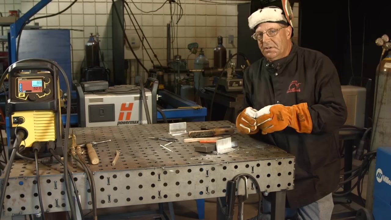
42. Lightly remove slag and residue. "Lightly try to peck this stuff off of here." Use a tool such as pliers or a chipping hammer to gently tap and remove slag or flux residue from the welded joint, taking care to avoid damaging the underlying weld bead.
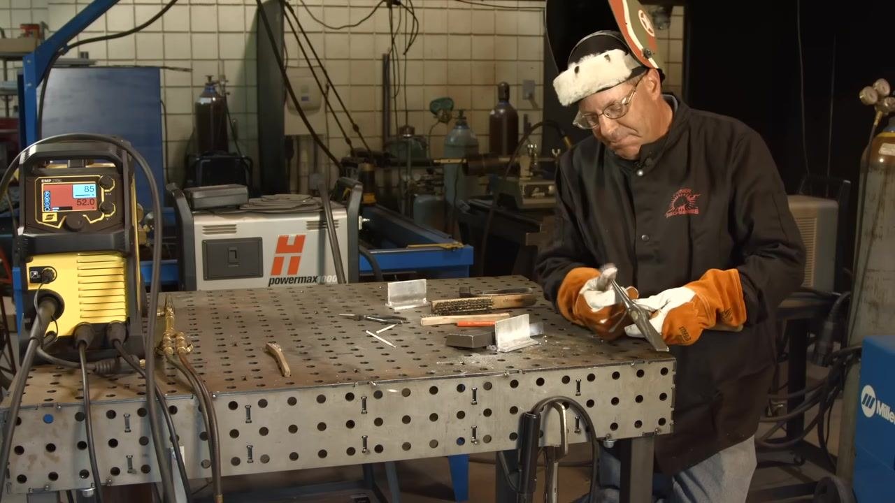
43. Cool the workpiece before further cleaning. "Let this cool off, then work on it to see if a bead can be brought out that's clearly visible." A close-up of the welded joint shows gloved hands and a tool in motion, indicating the process of cleaning and cooling, with slag and debris visible around the weld area.
44. Continue cleaning the welded joint. Return to the table and use a wire brush or chipping hammer to further clean the weld bead. Keep gloves and helmet on for safety, with the welding machine remaining set to 85A/52.0V.
45. Inspect the cleaned weld bead. Examine a close-up of the cleaned weld bead and joint. Most of the slag and residue should be removed, revealing the underlying weld structure. Check for any remaining imperfections or areas needing additional cleaning.
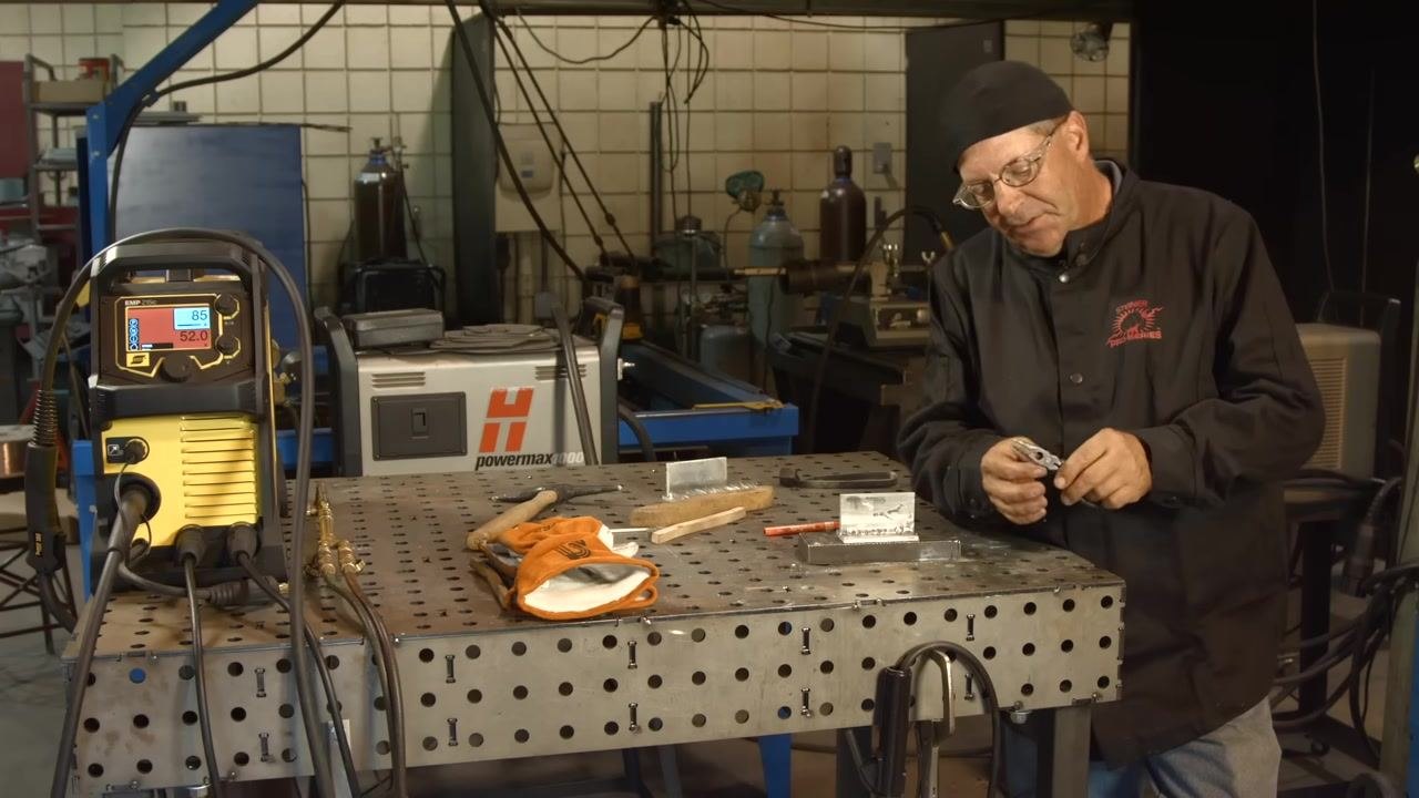
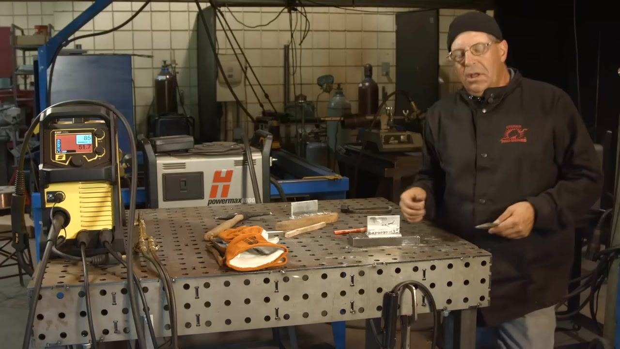
46. Review the weld results. "I cleaned this all up. This was going to be a little rough, and it was a little rough." Standing at the table without gloves and helmet, holding a tool and the cleaned workpiece, the welding machine display now shows 85A and 51.7V, with tools, gloves, and cleaned metal pieces arranged on the table.
47. Use pliers to remove stubborn residue. "Pliers were used to knock some of this stuff around." Use pliers to manipulate or remove remaining residue from the electrode or workpiece, demonstrating proper technique for handling stubborn slag or flux.
48. Identify flux residue characteristics. "This heavy salt-looking residue is just the nature of that flux." The residue appears granular or salt-like — this is a normal byproduct of the flux used with low hydrogen electrodes.
49. Point out missed areas in the weld. "This area right here was kind of missed." Examine the welded joint closely, using pliers to point at a specific area where cleaning or welding was incomplete.
50. Note arc-striking and weld-pool visibility challenges. "When the arc was struck, the pool was hard to see at the very beginning." This highlights the challenges of arc striking and initial weld-pool visibility, especially on aluminum.
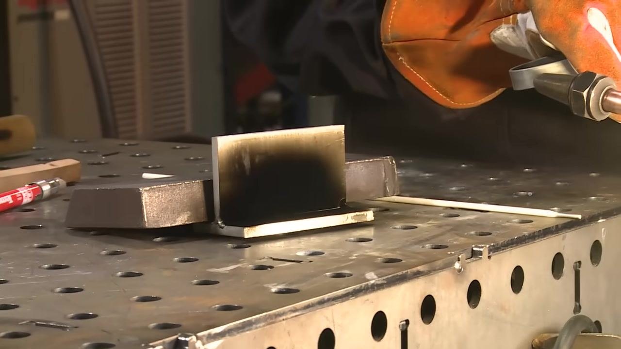
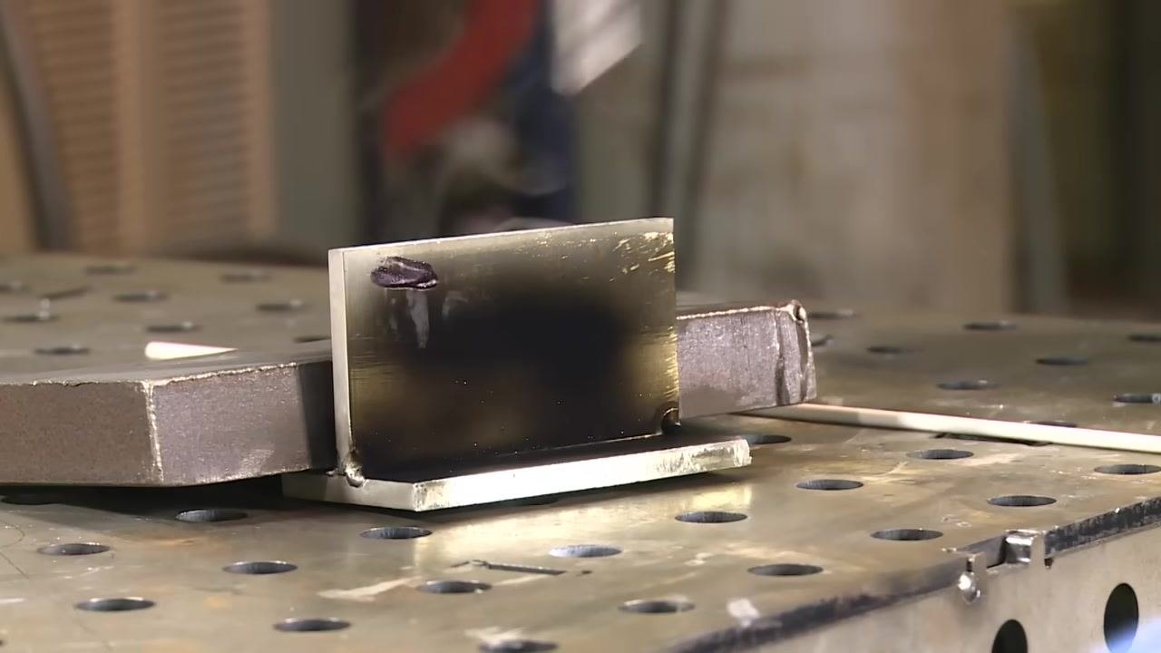
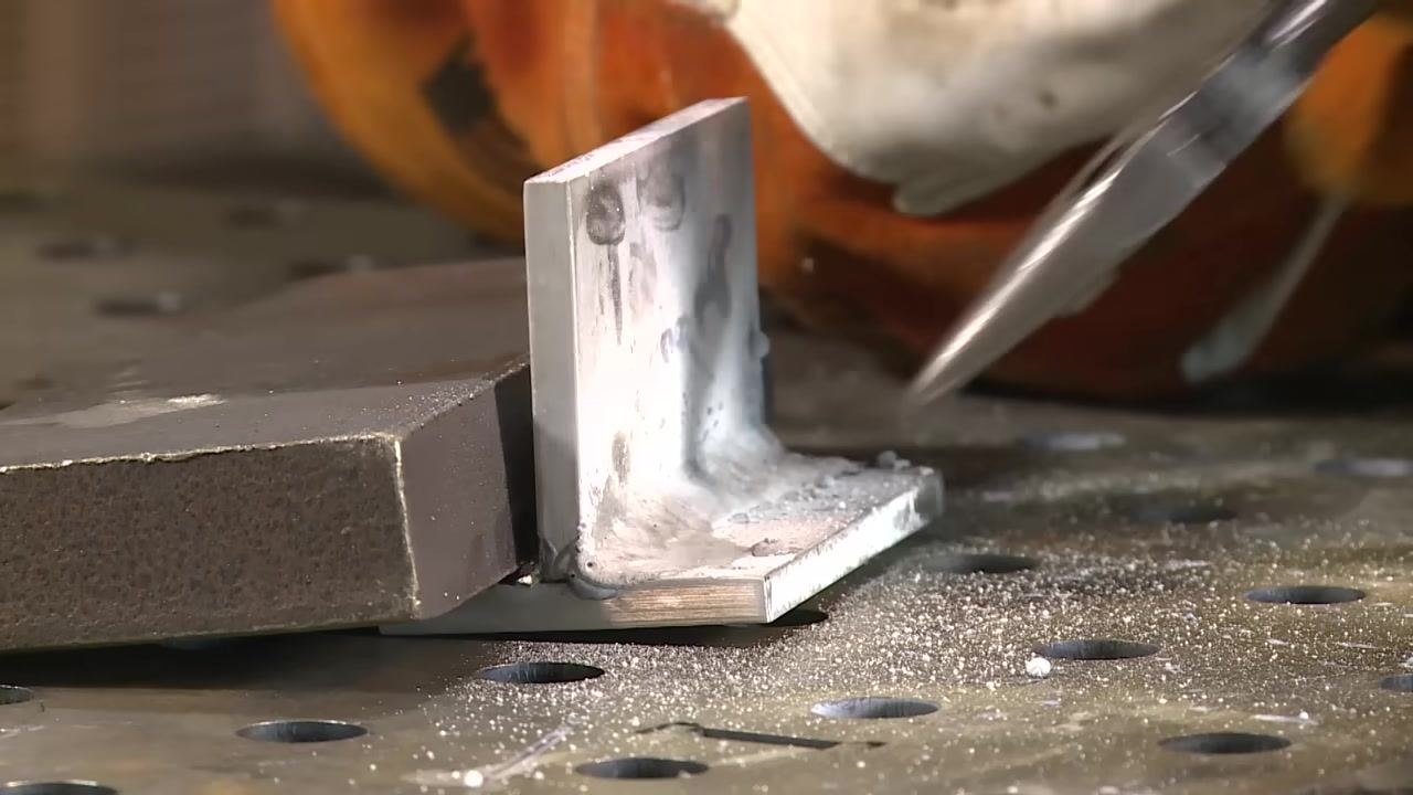
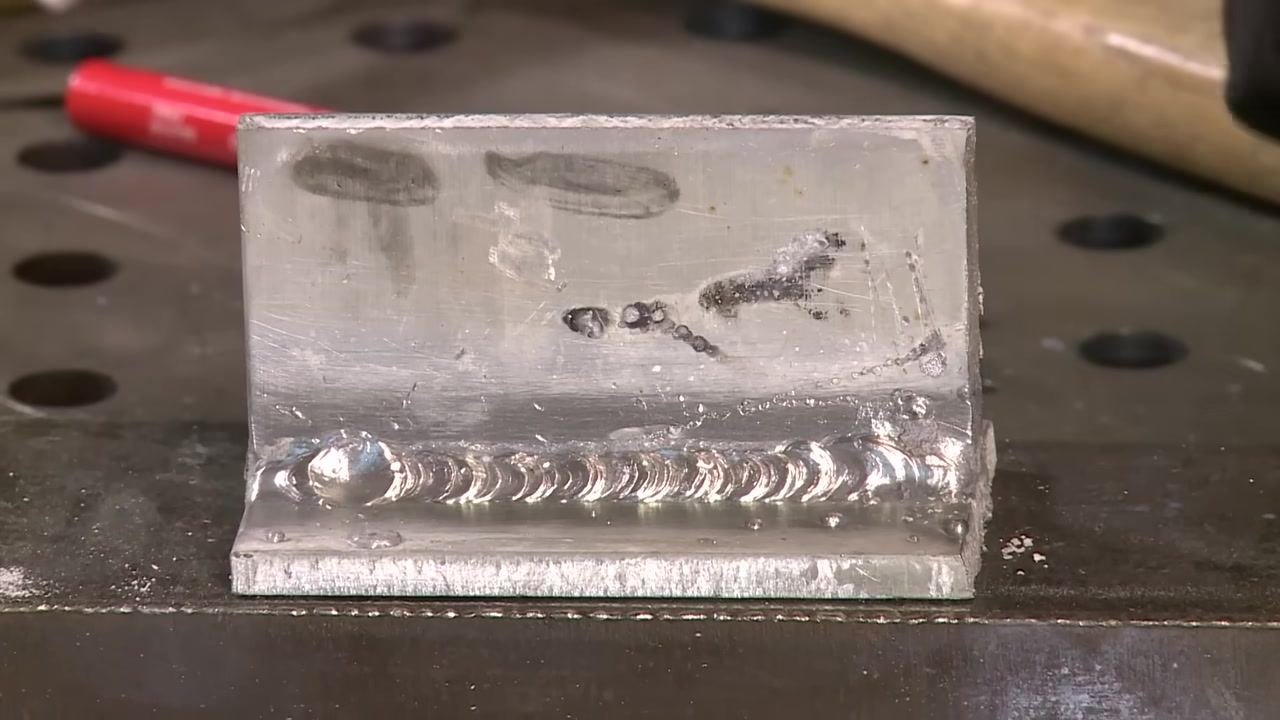
51. Inspect the finished aluminum joint. Note the presence of spatter on the vertical plate, with roughly two-thirds of the surface showing dark spots and marks. The weld bead along the base of the joint displays a consistent ripple pattern.
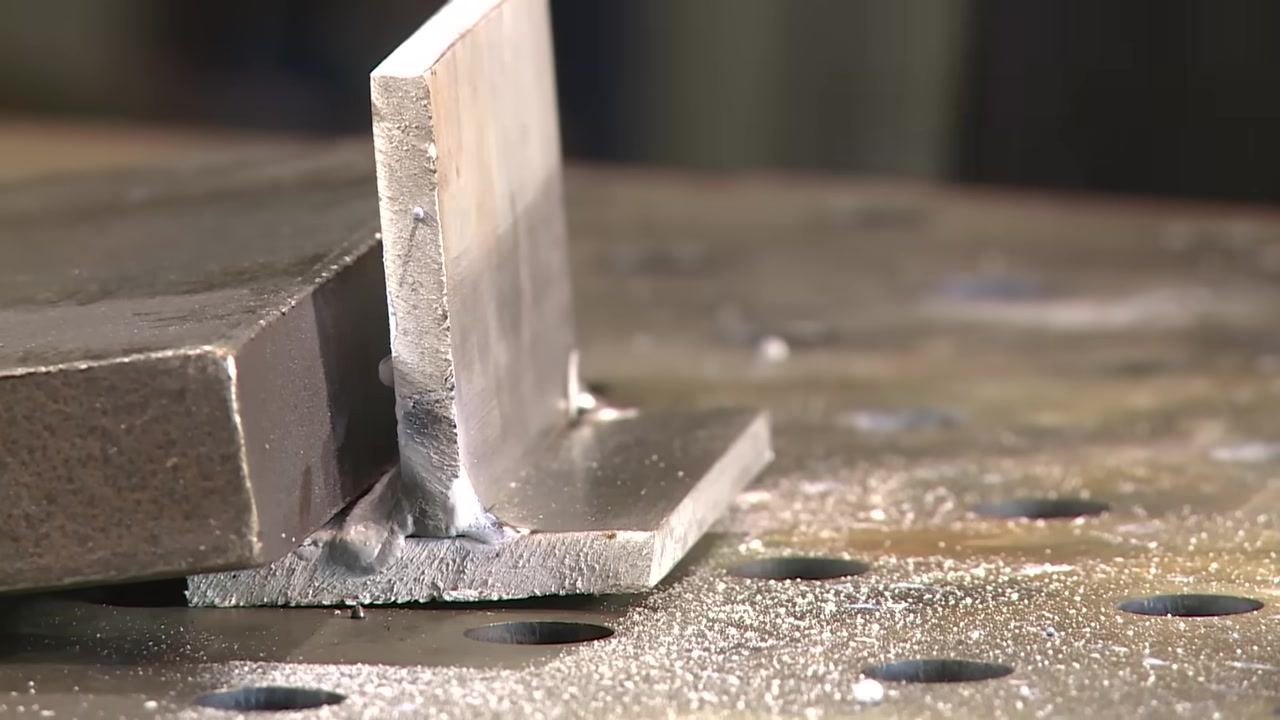
52. Identify excess aluminum for cleanup. Locate the large blob of aluminum at the left end of the weld bead. This excess material can be removed using sanders and files for a cleaner finish.
53. Assess the overall weld profile. Examine the shape and consistency of the weld bead. Confirm the weld has an acceptable profile for an aluminum weld, even if it is not as refined as a TIG or spool gun weld, noting any continued spatter or surface imperfections.
54. Compare weld quality to other welding methods. The weld is functional, even though it may not match the appearance of TIG or spray wire feed welds. It is structurally sound and suitable for field repairs.
55. Review the weld in context of the repair goal. This procedure is functional for field repairs of this type — a hand gestures near the weld to emphasize the points discussed.
56. Inspect the opposite side of the weld. Rotate the workpiece to view the opposite side of the weld. Identify another blob of aluminum at the end of the weld bead, indicating a minor imperfection, with a tool pointing at the bead for closer inspection.
57. Note personal finishing preferences. Some finishing steps seen on professional welds may be skipped by preference. The weld bead and surface show a natural finish without excessive grinding or polishing.
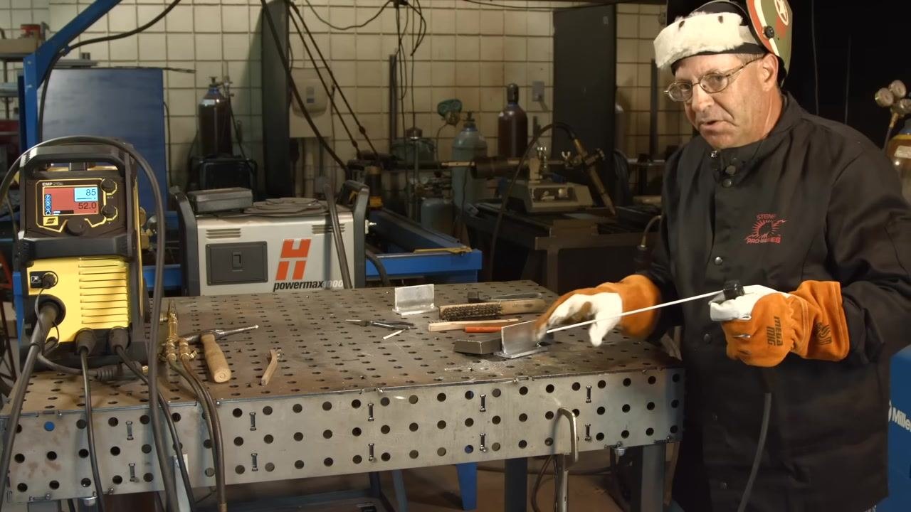
58. Reflect on realistic weld aesthetics. Consider how often a visually perfect aluminum weld is actually seen on trailers or commercial products. A rod or tool points to specific areas of the weld bead to highlight features and imperfections.
Addressing weld craters and final checks
59. Identify the weld crater at termination. Observe the end of the aluminum weld bead where a noticeable crater is present. A rod or pointer indicates the exact location of the crater at the weld termination. Filling in this crater is essential to prevent weaknesses.
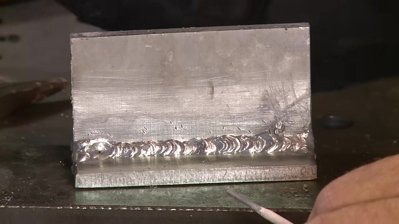
60. Examine the crater and star hole defect. Focus on the crater at the end of the weld bead, which features a small central hole known as a "star hole." This is a common defect when terminating aluminum welds.
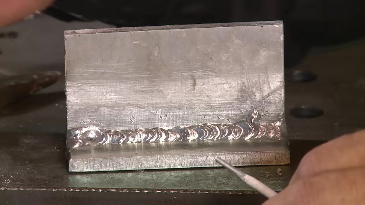
61. Understand the crack risk from unfilled craters. Consider a trailer under constant vibration: even a small crack or star hole in the crater can propagate under stress, leading to weld failure.
Safety note: Unfilled craters are a common failure point in vibrating or load-bearing applications — always fill weld terminations completely.
62. Fill weld craters completely. Ensure all weld terminations are properly filled to avoid the formation of craters and star holes, especially in critical repairs.
63. Blend and clean critical welds. If the weld is for a critical application, clean and blend the weld area thoroughly. Use a rod or pointer to indicate areas that may require additional attention.
64. Reflect on the goal of the demonstration. The goal of this procedure is to show the feasibility of stick welding aluminum, not to achieve a perfect weld. The weld bead and crater remain visible for reference.
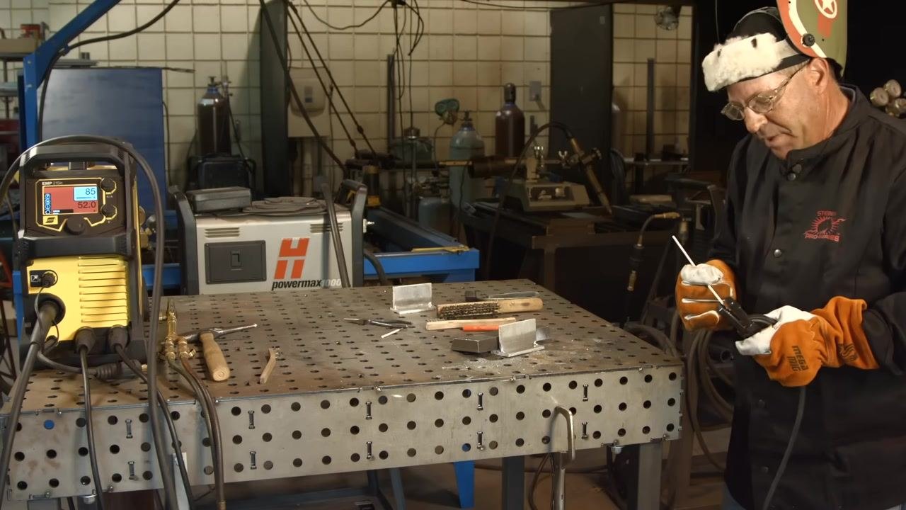
65. Review the workshop setup and safety. Confirm the full workshop environment is in order: welding equipment (such as a yellow welding machine with a digital display set to 85A/52.0V), tools (hammer, gloves, rods), and safety gear are all accounted for. Work at a perforated metal workbench while wearing safety glasses and a welding jacket.
Verification / Summary
Stick welding aluminum with a DC inverter is challenging but achievable for field repairs when the steps above are followed: set DCEP polarity, preheat the aluminum to roughly 400°F (using a Tempilstik or the soot trick), clean the metal with dedicated stainless steel tools, select a 3/32" electrode, and weld with a fast travel speed. Expect spatter, salty flux residue, and some ripple irregularity due to aluminum's softness — these are normal characteristics of the process, not signs of failure. Always fill weld terminations completely to avoid craters and star holes, which can crack under vibration or load. The finished weld will not match the appearance of a TIG or spray wire feed weld, but a properly filled, adequately cleaned bead with an acceptable profile is structurally sound and suitable for field repairs such as handrails or broken aluminum equipment.
Generation details: cost, quality tiers
Docsie billed 6,500 credits ($4.55) to analyze this 14-minute video at standard quality. The rewrite, template fill and Word/PDF exports were included. The same video at each quality tier:
| Quality | Frames sampled | Credits | Approx. cost |
|---|---|---|---|
| Draft | every 16-30 s | 3,500 | $2.45 |
| Standard (this guide) | every 8-15 s | 7,000 | $4.90 |
| Detailed | every 4-7 s | 14,000 | $9.80 |
| Ultra | every 1-3 s | 28,000 | $19.60 |
Credits priced at $0.70 per 1,000; plans include a monthly allowance. Enterprise customers on on-premise or bring-your-own-model deployments run this on their own inference and pay no per-video credits.
Generated by Docsie Video-to-Docs on 2026-09-10 from a 12-minute video. Screenshots are frames from the source video and belong to their creator, Weld.com, whose original is embedded above. If you own this video and want the guide removed or credited differently, contact us and we will act within one business day.