
How to Use a Dial Indicator
This standard operating procedure explains how to use a dial indicator to measure lateral runout on a brake rotor. It covers attaching the dial indicator to a rigid fixture, taking accurate runout measurements, and identifying the correction plate needed if runout exceeds specification.
Video: Chapter 4: Using the Dial Indicator by BrakeAlign (2009). All credit for the demonstration goes to the creator; watch the original on YouTube. The written guide below was generated from this video by Docsie. Creator? Request a change or removal.
Purpose
This standard operating procedure explains how to use a dial indicator to measure lateral runout on a brake rotor. It covers attaching the dial indicator to a rigid fixture, taking accurate runout measurements, and identifying the correction plate needed if runout exceeds specification.
Scope
This procedure applies to technicians measuring brake rotor runout as part of a brake service or diagnostic inspection. It covers setup of the dial indicator assembly through selection of the correct brake align correction plate.
Required equipment
- Dial indicator with flex arm and contact tip
- Vise grip clamp
- Brake align correction plates
- Brake align application chart
- Marker (for marking high spot locations)
Secure the vise grip to the vehicle
Clamp the vise grip securely onto a rigid part of the vehicle's suspension or knuckle. Adjust the knurled knob in the vise grip handle to ensure a tight, stable grip. Confirm that the vise grip does not move when you lightly push or pull it.
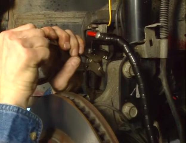
Position the vise grip near the rotor
Ensure the vise grip is located close enough to the brake rotor so that the flex arm and dial indicator gauge can reach and make contact with the rotor's friction surface. The flex arm should extend comfortably from the vise grip to the rotor.
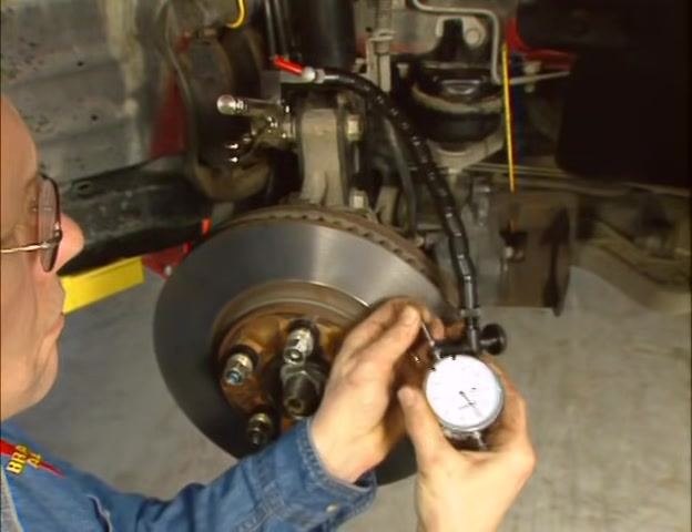
Tighten the contact tip
Check that the contact tip of the dial indicator is tightened securely. Use your fingers to confirm the tip does not wobble or move.
Set the dial indicator position
Adjust the flex arm so the dial indicator gauge contacts the rotor's friction surface approximately half an inch from its outermost diameter. Rotate the knurled ring at the end of the flex arm clockwise to remove any slack, holding the dial indicator in the desired position.
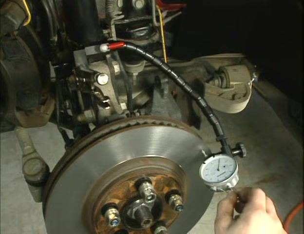
Lock the flex arm and gauge in place
With the slack removed, turn the cam lever to secure the flex arm and dial indicator rigidly in place. The cam lever should be in line with the flex arm when fully tightened.
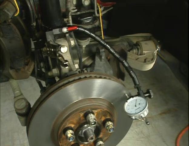
Verify contact and stability
Lift the spring-loaded needle of the dial indicator up off the rotor a few times. Ensure the tip of the needle makes good contact with the rotor's friction surface each time, and confirm there is no movement in the dial indicator or flex arm during this process.
Check for flex arm and gauge movement
Observe the setup to ensure the dial indicator and flex arm remain stable and do not shift when the needle is lifted and released.
Rotate the rotor and observe the gauge
Always rotate the rotor in the clockwise direction when checking for lateral runout. Watch the dial indicator gauge as it oscillates back and forth between the high and low points on the rotor. The lowest reading on the gauge indicates the lowest spot on the rotor.
Zero the gauge at the low spot
Once you find the low spot, gently push the gauge to bring the needle to top dead center, pointing directly at the rotor. Rotate the face of the gauge so the needle points to zero at this location, then rotate the rotor again to confirm the low spot is exactly at zero.
Confirm the zero setting
Double-check the gauge to ensure the needle remains at zero when the rotor is at the low spot.
At this point, the dial indicator is securely attached and properly set up to measure rotor runout accurately.
Rotate the rotor to find the high spot
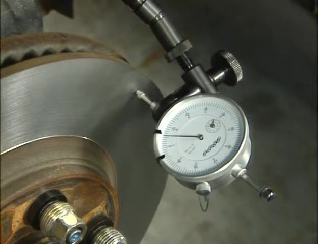
With the dial indicator zeroed at the low spot, continue rotating the rotor clockwise. Observe the gauge as you rotate to identify the highest reading, which indicates the high spot, or maximum lateral runout. Note the amount of runout at the high spot, measured in thousandths of an inch. In this example, the runout exceeds the manufacturer's specification of 0.002" (two thousandths); the measured runout is 0.006" (six thousandths).
Record the high spot reading
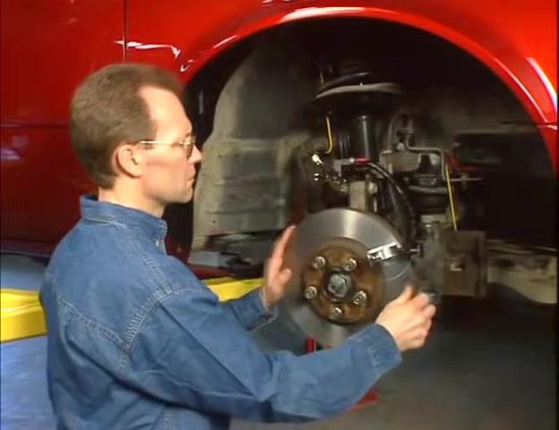
Stop rotating the rotor when the dial indicator needle reaches its highest reading. The location where the needle contacts the rotor at this point is the exact high spot.
Prepare for correction
Recognize that lateral runout exceeding specification will require correction using brake align correction plates. Identify and prepare the appropriate correction plate for the next steps.
Mark the high spot on the rotor and wheel stud
Using the supplied marker, mark the exact location of the high spot on both the rotor and the closest wheel stud. Marking both points is critical for accurate alignment during correction.
Bring the high spot to top dead center
Rotate the rotor so that the marked high spot is positioned at the 12 o'clock (top dead center) position. This orientation assists in the installation of the correction plate.
Consult the brake align application chart
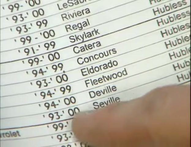
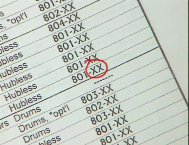
Locate the year and model of the vehicle you are servicing in the brake align application chart. For a 1999 Cadillac Seville STS, the chart identifies that an 801 correction plate is required.
Identify the correct correction plate part number
Note that the correction plate part number includes "XX," which specifies the amount of taper or correction needed. Refer to the chart to determine the exact part number for your application.
Verification and summary
By following this procedure, you will have securely attached the dial indicator, measured lateral runout at the low and high spots of the rotor, marked the high spot on both the rotor and the nearest wheel stud, and identified the correct correction plate for your vehicle application.
What's next
Proceed to install the correction plate as specified in the next section of the guide.
Generation details: cost, quality tiers
Docsie billed 2,000 credits ($1.40) to analyze this 4-minute video at standard quality. The rewrite, template fill and Word/PDF exports were included. The same video at each quality tier:
| Quality | Frames sampled | Credits | Approx. cost |
|---|---|---|---|
| Draft | every 16-30 s | 1,000 | $0.70 |
| Standard (this guide) | every 8-15 s | 2,000 | $1.40 |
| Detailed | every 4-7 s | 4,000 | $2.80 |
| Ultra | every 1-3 s | 8,000 | $5.60 |
Credits priced at $0.70 per 1,000; plans include a monthly allowance. Enterprise customers on on-premise or bring-your-own-model deployments run this on their own inference and pay no per-video credits.
Generated by Docsie Video-to-Docs on 2026-09-09 from a 3-minute video. Screenshots are frames from the source video and belong to their creator, BrakeAlign, whose original is embedded above. If you own this video and want the guide removed or credited differently, contact us and we will act within one business day.