
How to Test a Fuse With a Multimeter
This document explains how to test a fuse with a multimeter to determine whether it is functional or blown. It covers checking a fuse for continuity, verifying resistance readings, and testing several common fuse types, including automotive blade fuses, plug-type fuses, cartridge fuses, and knife blade fuses.
Video: How to Check a Fuse by Testing it with a Multimeter by GalcoTV (2015). All credit for the demonstration goes to the creator; watch the original on YouTube. The written guide below was generated from this video by Docsie. Creator? Request a change or removal.
This document explains how to test a fuse with a multimeter to determine whether it is functional or blown. It covers checking a fuse for continuity, verifying resistance readings, and testing several common fuse types, including automotive blade fuses, plug-type fuses, cartridge fuses, and knife blade fuses.
Purpose
The purpose of this procedure is to provide a reliable method for confirming whether a fuse is good or needs replacement, using a digital multimeter's continuity and resistance functions.
Scope
This procedure applies to anyone testing fuses removed from a machine or electrical circuit, including automotive blade fuses, plug-type residential fuses, cartridge fuses, and knife blade fuses.

Required equipment
- A digital multimeter with continuity and resistance (ohm) test functions
- The fuse (or fuses) to be tested
Safety precautions
- Always remove the fuse completely from the machine or circuit before testing it.
- Keep the fuse away from any power source. Testing a powered fuse can produce inaccurate readings and create a safety hazard.
Procedure
Remove the fuse from the machine
Ensure the fuse is completely removed from the machine or circuit before you begin testing. Confirm it is disconnected from any power source to avoid inaccurate readings or safety hazards.
Understand how a fuse works
A working fuse acts as a bridge, allowing current to flow from one side to the other and complete the circuit. If the current exceeds the fuse's rating, the internal bridge breaks and stops the current flow. Understanding this behavior helps you interpret the multimeter readings in the following steps.
Prepare the multimeter for testing
Use a digital multimeter that includes both continuity and resistance (ohm) test functions.
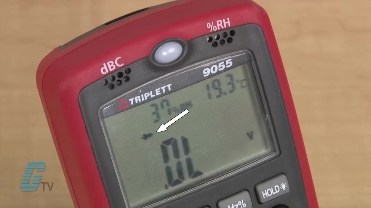
- The continuity test is usually represented by a radio wave symbol.
- The resistance test is represented by the omega (Ω) symbol.
Set the multimeter to continuity mode
Turn the multimeter's dial to the continuity setting, indicated by the radio wave symbol. Many digital multimeters emit an audible beep when continuity is detected.
Verify multimeter functionality
Touch the two probes together and listen for a beep, or check the display for a reading. This confirms the multimeter is working properly before you test the fuse.
Test the fuse for continuity
Place one probe on each end of the fuse. If the fuse is good, the multimeter will beep, indicating an electrical connection between both ends.
Set the multimeter to resistance (ohms) mode
Turn the dial to the resistance setting, indicated by the Ω symbol. When the probes are not touching anything, the display should show "OL" (open loop).
Check the multimeter resistance reading
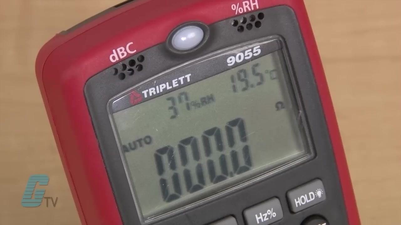
Touch the two probes together. The display should show a value close to zero (for example, 0.000), confirming the meter is functioning correctly.
Test the fuse for resistance
Place one probe on each end of the fuse.
- A good fuse shows a reading close to zero ohms, indicating low resistance and a complete circuit.
- If the display shows "OL" or a very high resistance, the fuse is blown and should be replaced.
Alternative: Use the diode check function
Some multimeters include a diode check function that can also be used to test fuses. Refer to your multimeter's manual for specific instructions on using this feature. Whichever function you use, follow the same probe placement steps described for resistance testing.
Identify connection points for different fuse types
Different fuses have unique connection points for testing:
- Automotive blade fuses: Test at the two metal prongs extending from the plastic body.
- Plug-type fuses (older residential): Test at the center of the bottom and the threaded metal base.
- Cartridge fuses: Test at the metallic ends of the cylindrical body.
- Knife blade fuses: Test at the protruding metal blades at each end.
Test a plug-type fuse
For plug-type fuses, commonly found in older residential wiring, place one probe on the center contact at the bottom and the other probe on the threaded metal base. This ensures you are testing across the internal fuse element.
Test a knife blade or cartridge fuse
Place one probe on each metallic end of the fuse, ensuring good contact with the metal surfaces for an accurate reading.
- If the multimeter shows continuity or a low resistance value, the fuse is good.
- If it shows "OL" or high resistance, the fuse is blown.
Visually inspect fuses for signs of blown elements
Many fuses have a visible indicator, such as a broken wire or a darkened glass tube, that shows whether they are blown. Always confirm this visual assessment with a multimeter test for certainty.
Verification and summary
By following these steps, you can accurately determine whether a fuse is functional or needs replacement using a digital multimeter. The same continuity and resistance procedures apply across fuse types, including automotive blade fuses, plug-type fuses, cartridge fuses, and knife blade fuses, allowing you to confirm electrical safety and proper circuit protection.
Generation details: cost, quality tiers
Docsie billed 1,500 credits ($1.05) to analyze this 3-minute video at standard quality. The rewrite, template fill and Word/PDF exports were included. The same video at each quality tier:
| Quality | Frames sampled | Credits | Approx. cost |
|---|---|---|---|
| Draft | every 16-30 s | 750 | $0.52 |
| Standard (this guide) | every 8-15 s | 1,500 | $1.05 |
| Detailed | every 4-7 s | 3,000 | $2.10 |
| Ultra | every 1-3 s | 6,000 | $4.20 |
Credits priced at $0.70 per 1,000; plans include a monthly allowance. Enterprise customers on on-premise or bring-your-own-model deployments run this on their own inference and pay no per-video credits.
Generated by Docsie Video-to-Docs on 2026-09-08 from a 2-minute video. Screenshots are frames from the source video and belong to their creator, GalcoTV, whose original is embedded above. If you own this video and want the guide removed or credited differently, contact us and we will act within one business day.