
How to Test a Capacitor With a Multimeter
This procedure explains how to test a capacitor with a multimeter (or a dedicated capacitor tester) to determine whether it is functioning correctly. A capacitor is a component that stores an electrical charge and then releases it, and it is commonly used to help start and run motors and compressors. Following these steps allows you to identify a defective capacitor, safely discharge it, and verify both its resistance behavior and its capacitance rating before deciding whether it needs to be replaced.
Video: How to Test a Motor Capacitor with a Multimeter | Start & Run Capacitor Test by RepairClinic.com (2014). All credit for the demonstration goes to the creator; watch the original on YouTube. The written guide below was generated from this video by Docsie. Creator? Request a change or removal.
This procedure explains how to test a capacitor with a multimeter (or a dedicated capacitor tester) to determine whether it is functioning correctly. A capacitor is a component that stores an electrical charge and then releases it, and it is commonly used to help start and run motors and compressors. Following these steps allows you to identify a defective capacitor, safely discharge it, and verify both its resistance behavior and its capacitance rating before deciding whether it needs to be replaced.
Purpose
The purpose of this procedure is to guide you through inspecting, discharging, and electrically testing a capacitor so you can determine whether it is operating within its specified range or needs to be replaced.
Scope
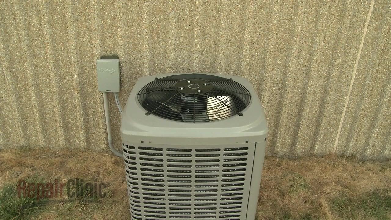
This procedure applies to capacitors found in common household and HVAC equipment, including:

- Central air conditioners
- Furnaces
- Other heating and cooling equipment
- Appliances such as refrigerators and washing machines
It covers both single capacitors and dual (run) capacitors.
Required equipment
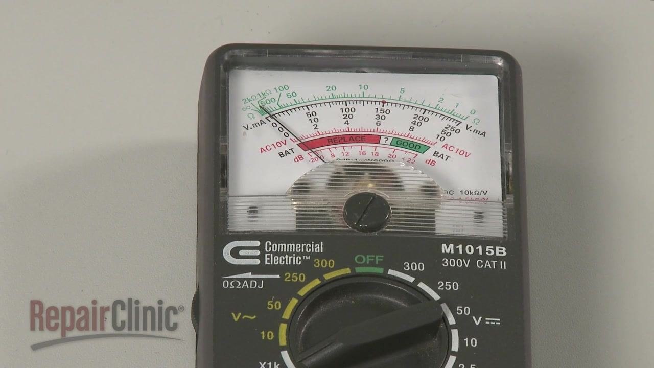
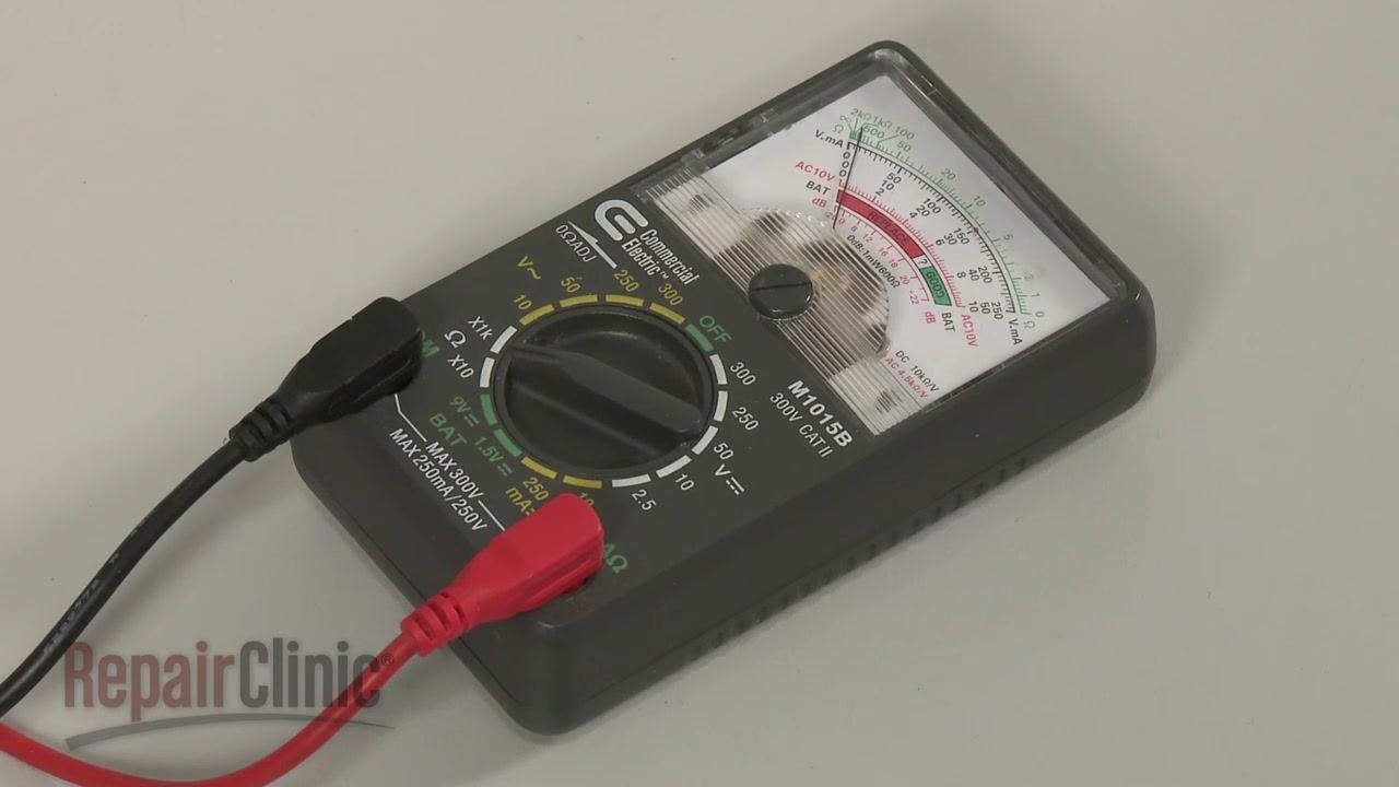
- Analog-style ohm meter or a dedicated capacitor tester
- Multimeter with a capacitance testing function (or a standalone capacitance tester)
- Insulated-handle screwdriver (for safely discharging the capacitor)
Procedure
Recognize typical capacitor applications
Capacitors are commonly used to help start and run motors and compressors in equipment such as central air conditioners and furnaces.

Identify signs of capacitor failure
If a motor or compressor does not start or starts slowly, suspect a defective capacitor.
Inspect the capacitor body for bulging or leaking. If either sign is present, replace the capacitor immediately without testing it further.
Prepare to test the capacitor
If there are no visible signs of damage, proceed to test the capacitor to confirm whether it is functioning properly. The first test checks whether the capacitor can store and release an electrical charge, and it can be performed using an analog-style ohm meter or a dedicated capacitor tester.
Discharge the capacitor safely
Before handling or testing the capacitor, release any stored electrical charge to avoid injury. Use a screwdriver with an insulated handle, and place it across each set of terminals on the capacitor.
Warning: Do not touch the metal blade of the screwdriver while discharging the capacitor. Doing so can cause electric shock.
Set the range on the ohm meter
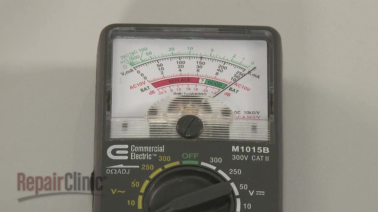
Rotate the range selection dial on the analog ohm meter to a setting of 1000 ohms or higher.
Calibrate the ohm meter
If necessary, pinch the probes together and adjust the needle to read zero on the scale before testing.
Test a single capacitor for resistance behavior
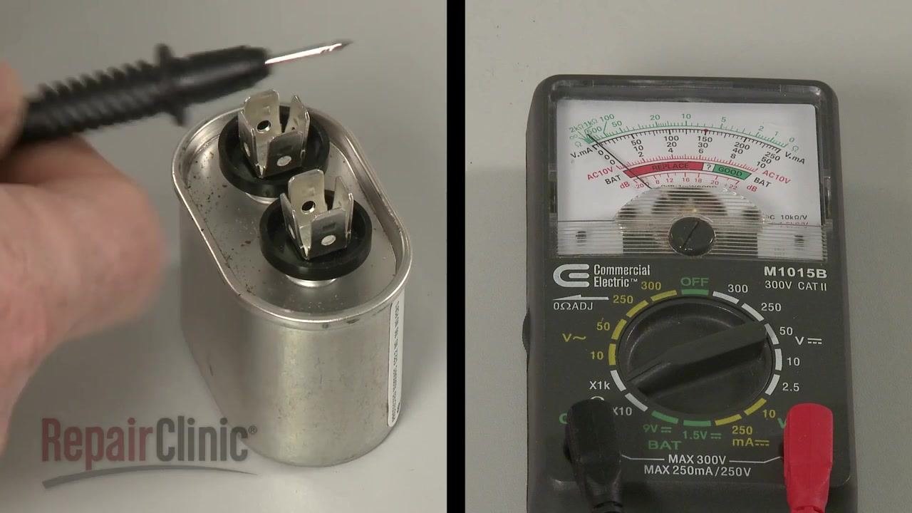
Touch one probe to one terminal of the capacitor and the second probe to the other terminal. Watch the meter needle: it should deflect toward zero ohms and then return toward infinite resistance.
Reverse the probes and repeat the test. The needle should behave the same way in both directions.
Result interpretation: If the needle does not move, or stays near zero ohms, the capacitor has failed and must be replaced.
Test a dual (run) capacitor for resistance behavior
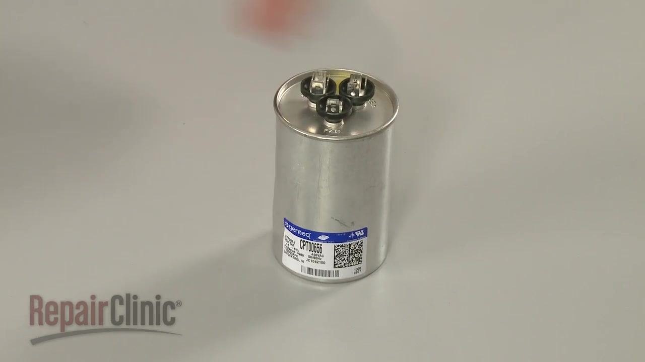
Identify the terminals on the dual capacitor. The common terminal is often marked "C", with the other terminals labeled "FAN" and "HERM" (or "COMP").
To test the fan circuit, touch one probe to the common terminal ("C") and the second probe to the fan terminal ("FAN"). The needle should deflect toward zero ohms and return to infinite resistance.
Repeat the same process for the HERM or COMP circuit by touching one probe to the common terminal ("C") and the second probe to the HERM or COMP terminal. The needle should again deflect toward zero ohms and return to infinite resistance.
Check the capacitor for a short to ground
Using a standard ohm meter, place one probe on each terminal, one at a time, while touching the second probe to the metal casing of the capacitor. No terminal should show continuity.
If the meter shows continuity (the needle moves), the capacitor is shorted to ground and must be replaced.

Prepare to test the capacitance rating
Obtain a capacitor tester or a multimeter with a capacitance testing function. The capacitance rating is measured in microfarads (µF).
Important: Confirm that the capacitor is fully discharged before performing this test.
Measure the microfarad rating of a single capacitor
Locate the microfarad (MFD) rating printed on the capacitor. For example, the capacitor shown is labeled "7.5 MFD 370 VAC".
Set your capacitance tester or multimeter to the appropriate microfarad range that matches the capacitor's rating, connect the tester probes to the capacitor terminals, and press the button on the tester to display the reading.
Compare the reading to the rating printed on the capacitor. The measured value should be close to the specified rating. If the reading is significantly lower than the rated value, replace the capacitor.
Measure the microfarad rating of a dual (run) capacitor
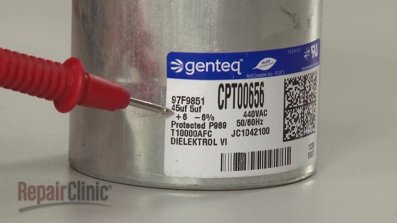
Identify the two microfarad ratings printed on the capacitor label. For example, "45uf 5uf" indicates 45 microfarads and 5 microfarads. The higher rating is typically for the HERM or COMP (compressor) circuit, and the lower rating is for the FAN circuit.
Test each circuit separately: connect the tester probes to the "C" (common) and "HERM" or "COMP" terminals to measure the higher rating, then connect the probes to the "C" (common) and "FAN" terminals to measure the lower rating. Press the button on the tester to display each reading and compare it to the corresponding rating on the label.
Interpret the capacitance test results
If the measured microfarad value for any section is significantly lower than the rating printed on the component, the capacitor is faulty and must be replaced.
Verification
A capacitor is functioning correctly when:
- The ohm meter needle deflects toward zero ohms and returns to infinite resistance during resistance testing (in both probe directions, and for each circuit on a dual capacitor).
- No terminal shows continuity when checked against the metal casing for a short to ground.
- The measured microfarad reading is close to the rating printed on the capacitor for each circuit tested.
If any of these checks fail—no needle movement, continuity to ground, or a significantly low microfarad reading—the capacitor should be replaced.
What's next
After confirming that a capacitor has failed any of these tests (visible bulging or leaking, no resistance deflection, continuity to ground, or a low microfarad reading), replace the capacitor with one matching the correct rating before returning the equipment to service.
Generation details: cost, quality tiers
Docsie billed 2,500 credits ($1.75) to analyze this 5-minute video at standard quality. The rewrite, template fill and Word/PDF exports were included. The same video at each quality tier:
| Quality | Frames sampled | Credits | Approx. cost |
|---|---|---|---|
| Draft | every 16-30 s | 1,250 | $0.88 |
| Standard (this guide) | every 8-15 s | 2,500 | $1.75 |
| Detailed | every 4-7 s | 5,000 | $3.50 |
| Ultra | every 1-3 s | 10,000 | $7.00 |
Credits priced at $0.70 per 1,000; plans include a monthly allowance. Enterprise customers on on-premise or bring-your-own-model deployments run this on their own inference and pay no per-video credits.
Generated by Docsie Video-to-Docs on 2026-09-08 from a 4-minute video. Screenshots are frames from the source video and belong to their creator, RepairClinic.com, whose original is embedded above. If you own this video and want the guide removed or credited differently, contact us and we will act within one business day.