
How to Hvac Preventive Maintenance Checklist
This HVAC preventive maintenance checklist walks you through a full inspection and service routine for a rooftop HVAC unit, from initial power verification through final performance testing. Following this checklist ensures the unit is safely de-energized, thoroughly cleaned, electrically sound, and restored to service with verified operating parameters. Use it as a standard reference each time you perform scheduled maintenance on a rooftop unit.
Video: HVAC PM Training Video by Sami Ayyat (2019). All credit for the demonstration goes to the creator; watch the original on YouTube. The written guide below was generated from this video by Docsie. Creator? Request a change or removal.
This HVAC preventive maintenance checklist walks you through a full inspection and service routine for a rooftop HVAC unit, from initial power verification through final performance testing. Following this checklist ensures the unit is safely de-energized, thoroughly cleaned, electrically sound, and restored to service with verified operating parameters. Use it as a standard reference each time you perform scheduled maintenance on a rooftop unit.
Purpose
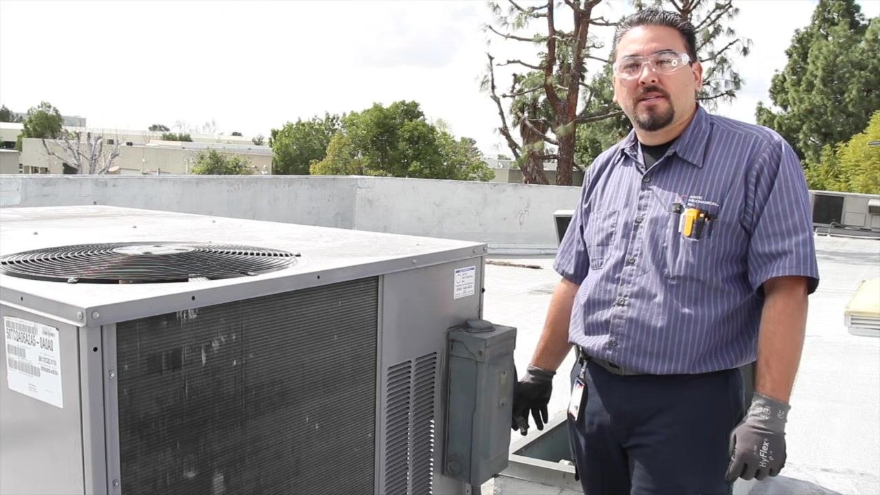
This procedure standardizes the steps required to inspect, clean, test, and service a rooftop HVAC unit. It covers electrical safety checks, coil cleaning, component inspection, filter and drain servicing, refrigerant system checks, and performance verification.
Scope
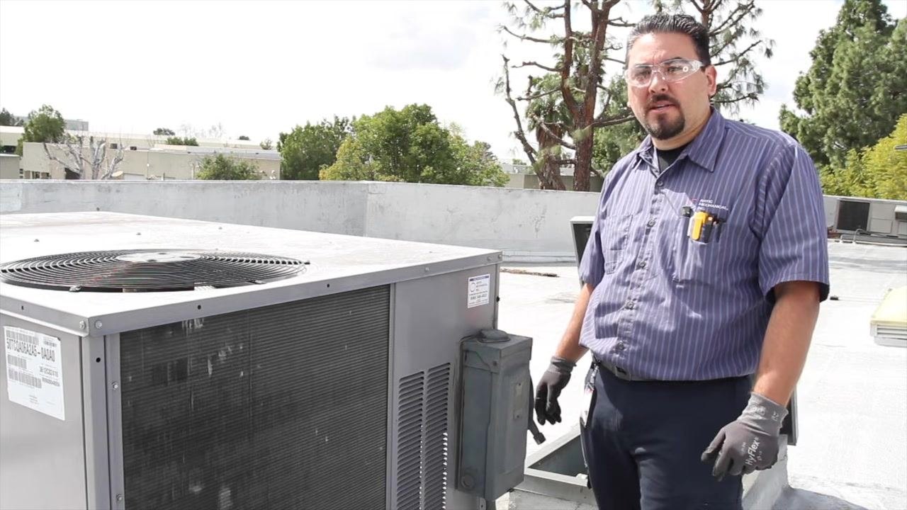
This checklist applies to technicians performing routine preventive maintenance on rooftop HVAC units, including units with condenser fan motors, blower assemblies, capacitors, contactors, and optional economizers.
Required equipment and PPE
- Safety glasses
- Gloves
- Multimeter (capable of voltage and microfarad readings)
- Insulated screwdriver
- Water hose or coil cleaning tool
- Clamp meter
- Digital thermometer or temperature probe
- Replacement air filters
- Panel drain pan tablets (pan taps)
- CO2 or compressed air source
- Pressure gauges
Prepare for maintenance
Before approaching the unit, put on appropriate personal protective equipment, including safety glasses and gloves.
Verify power to the unit
Check the voltage at the HVAC unit using a multimeter and confirm the unit is receiving the correct voltage. Inspect the fuses to ensure they are intact and functioning, and verify that power is present before proceeding.
De-energize the unit for safety
Turn off the power supply to the HVAC unit to de-energize it. Use a multimeter to confirm there is no voltage present before starting any work.
Wash out the coil
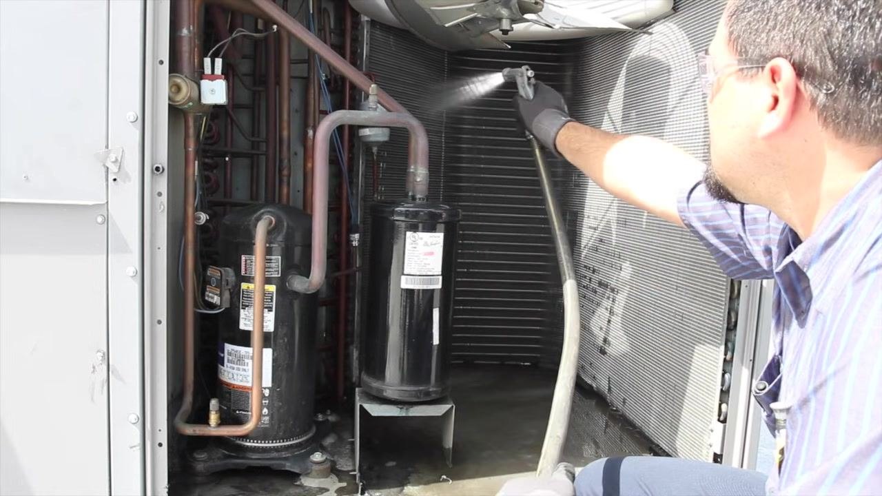
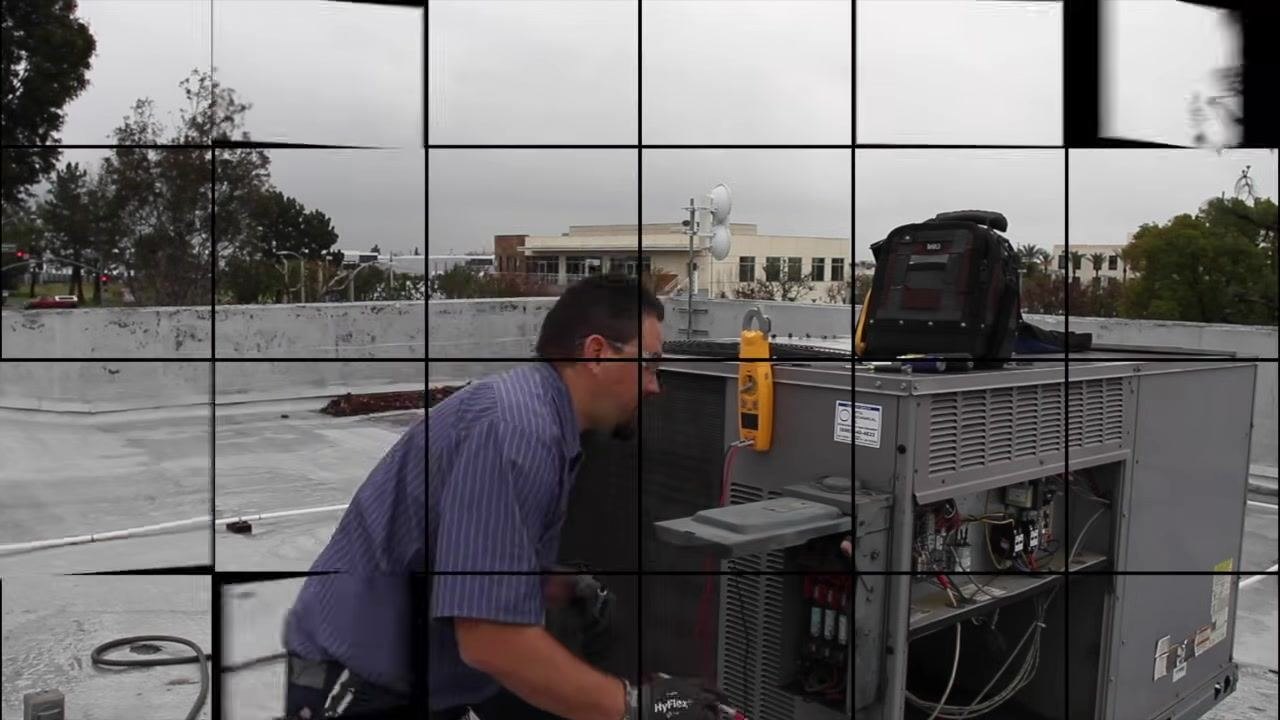
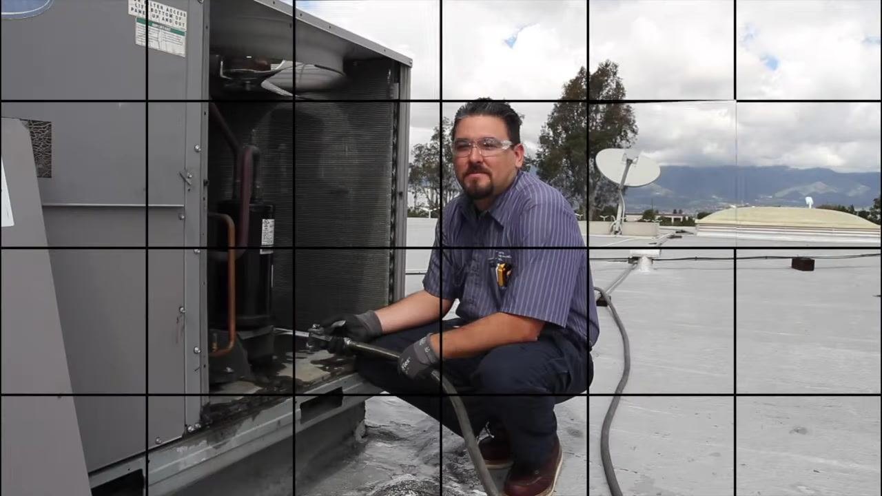
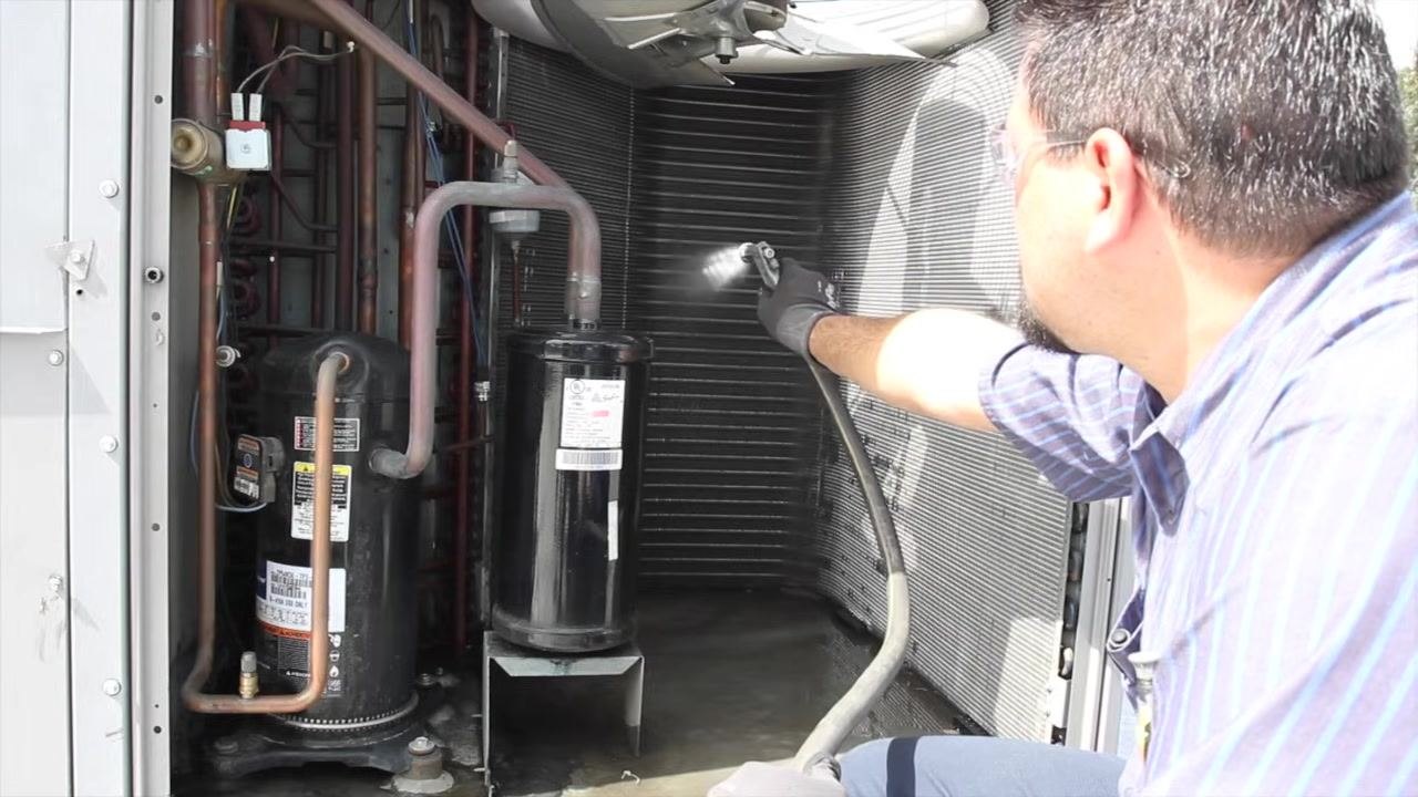
Open the access panel to the coil compartment. Inspect the floor of the unit for rust or corrosion to prevent water from penetrating into the building during cleaning. Use a water hose or coil cleaning tool to wash out the coil thoroughly, starting from one side and working around to ensure complete coverage.
Check for water intrusion risks
Ensure there are no standing roof tiles or debris that could allow water to enter the building or damage products inside. Confirm the area around the unit is clear before and after washing.
Clean the coil methodically
Begin at one side of the coil and systematically move around the unit, spraying water to remove dirt and debris until the entire coil is clean.
Following these steps ensures the HVAC unit is safely powered down, inspected, and cleaned, providing accurate pressure readings and preventing water damage during maintenance.
Inspect all electrical wiring
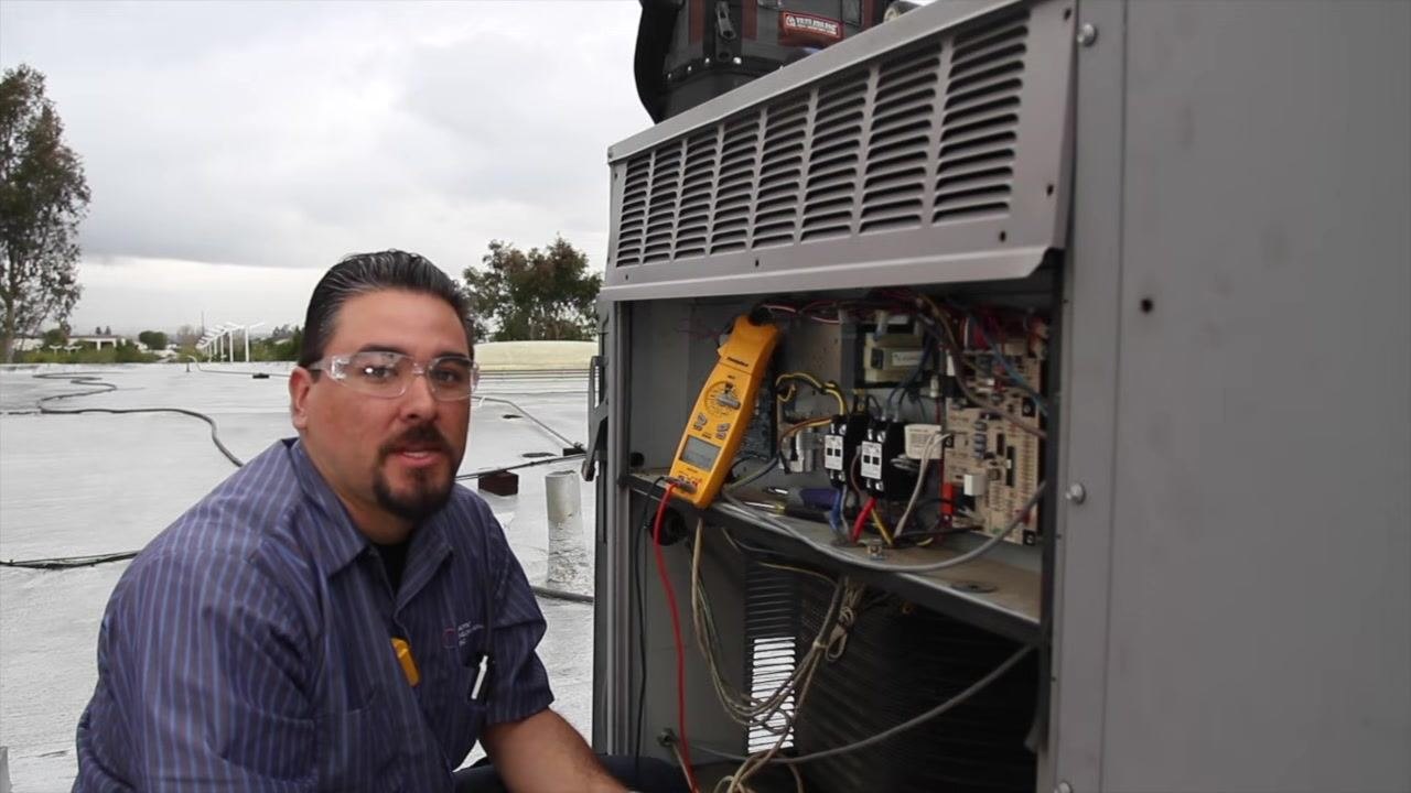
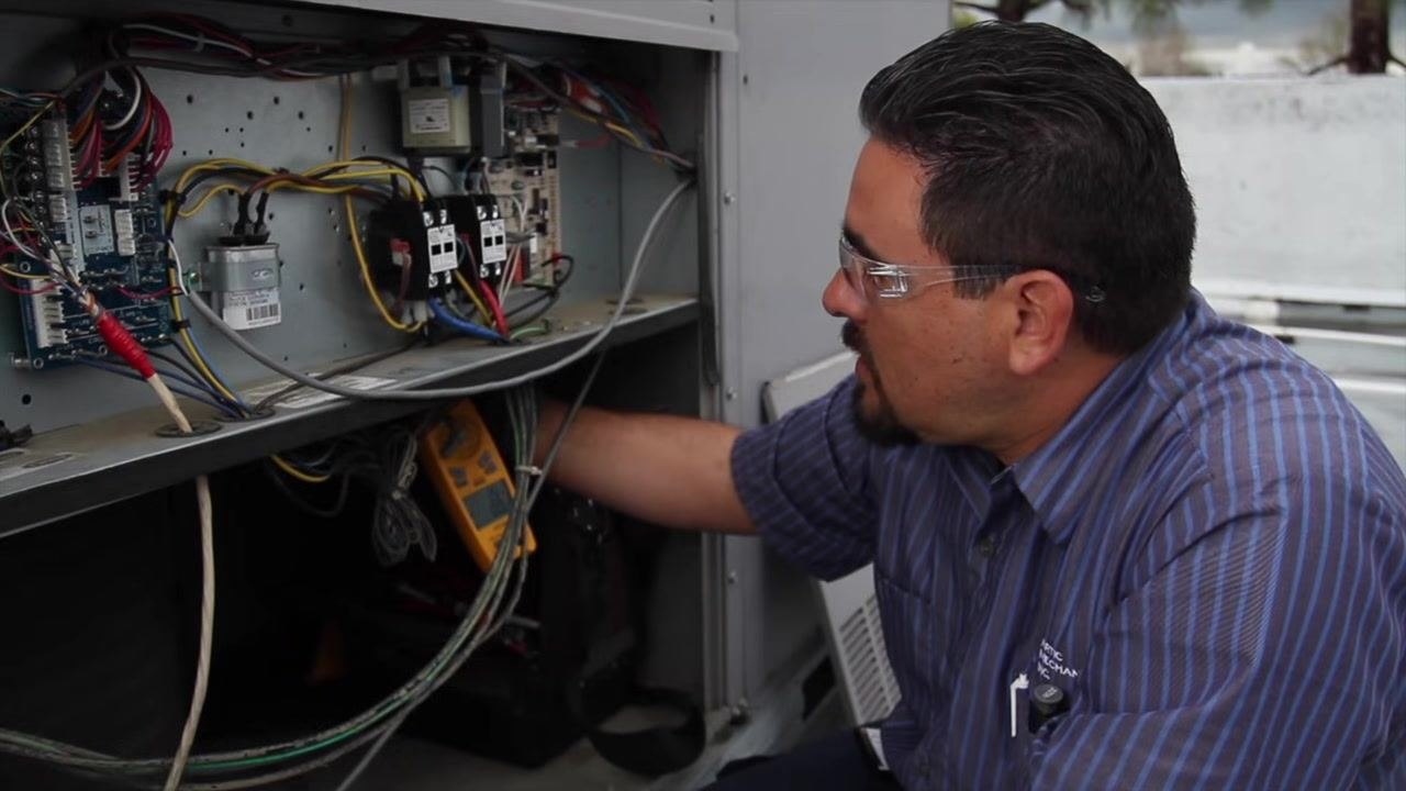
Open the electrical compartment of the HVAC unit. Visually inspect all wires to ensure they are properly routed and not at risk of being pulled out, and confirm that all wire connections are secure with no loose or exposed wires.
Check and tighten capacitor connections
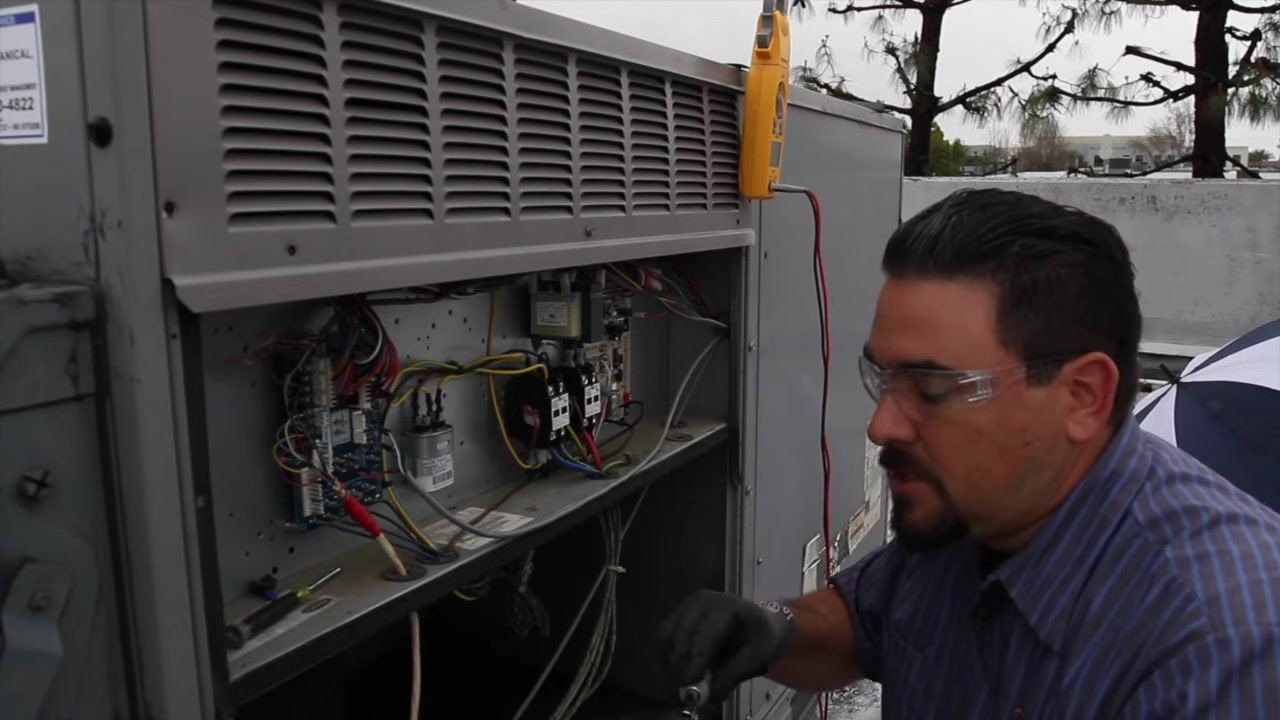
Locate the capacitors inside the electrical compartment. Use an insulated screwdriver to gently check each terminal connection on the capacitors and tighten any loose connections so all terminals are snug and secure.
Secure connections on contactors
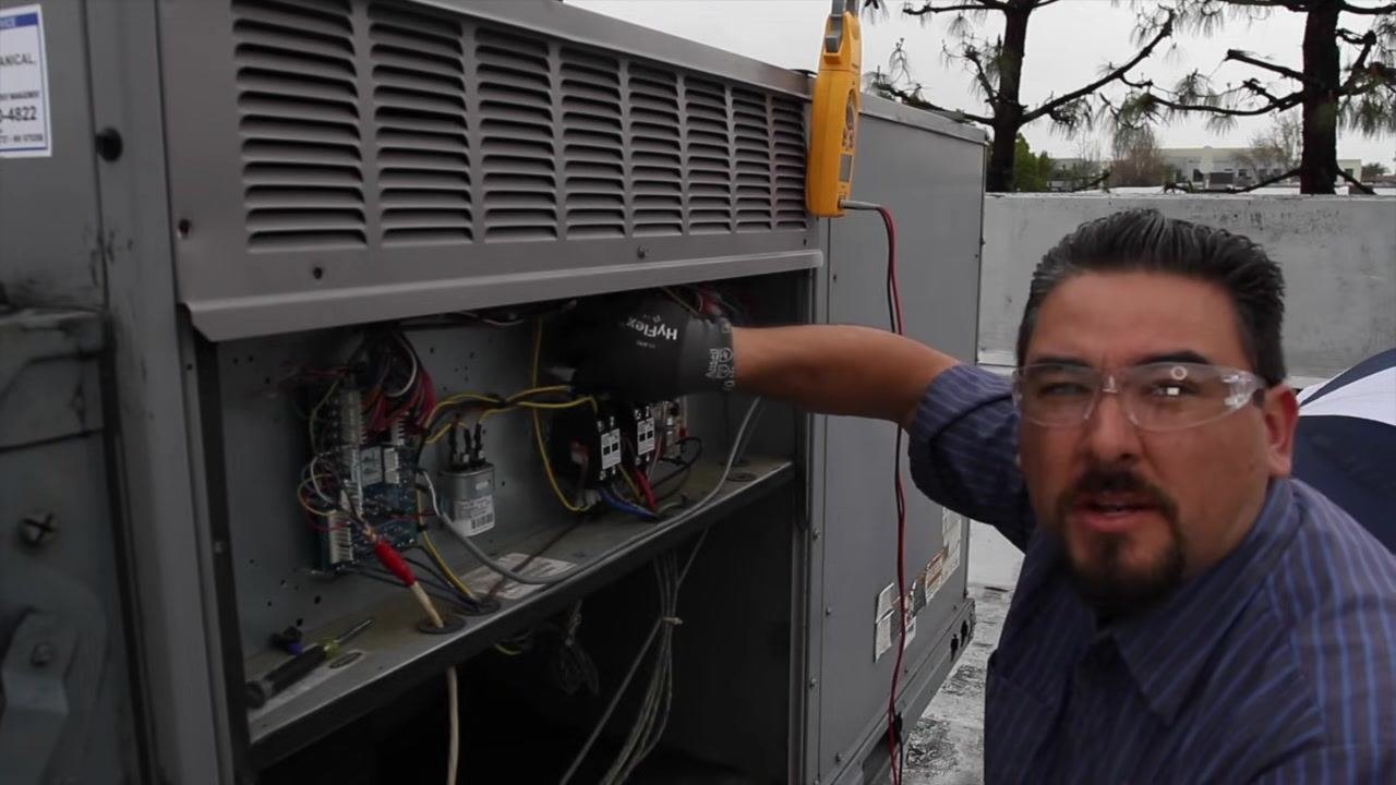
Identify the contactors, typically black rectangular components with multiple wire lugs. Check each lug to ensure connections are tight, and use a screwdriver to tighten any loose lugs as needed.
Inspect contactors for wear or pitting
Examine the contact surfaces of each contactor for signs of pitting, burning, or excessive wear. If contactors show signs of pitting or damage, plan for replacement. In this case, the contactors show no sign of pitting and appear to have been replaced recently.
Document the condition of electrical components
Note that the inspected contactors are in good condition and do not require replacement at this time. Record any maintenance actions taken, such as tightening connections or replacing components.
Following these steps ensures all electrical connections within the HVAC unit are secure, reducing the risk of electrical faults and prolonging the lifespan of critical components.
Test the condenser fan motor capacitor
After completing the electrical wiring assessment, check the capacitor for the condenser fan motor. Identify the capacitor and verify its rating: 5 microfarads (μF) ±6%, with an acceptable range of 4.7 to 5.3 μF.
- Discharge the capacitor before handling by using an insulated screwdriver to ground the terminals of the capacitor to itself, ensuring no stored power remains.
- Disconnect the wires from the capacitor terminals.
- Set your multimeter to the microfarads (μF) setting and measure the capacitance.
In this example, the reading is 3.9 μF, which is below the manufacturer's specification. If the reading falls outside the 4.7–5.3 μF range, the capacitor is out of spec; a low reading causes higher amperage draw on the motors, leading to premature wear. Replace the capacitor if it is out of specification.
Inspect the blower housing, pulley, and bearings
Check the condition of the blower housing for any signs of damage or debris. Inspect the pulley for proper alignment and verify there is no visible wear or damage. Rotate the bearings by hand to confirm they move smoothly and are not worn out. Examine the sheaves and pulleys for wear and verify alignment between the motor and the pulleys.
Reinstall the pulley and adjust belt tension
Reinstall the pulley onto the blower shaft if it was removed for inspection, and place the drive belt back onto the pulley. Check the belt tension to ensure it is not too tight or too loose, since proper tension is critical for efficient operation and to prevent premature wear.
Check the economizer, if present
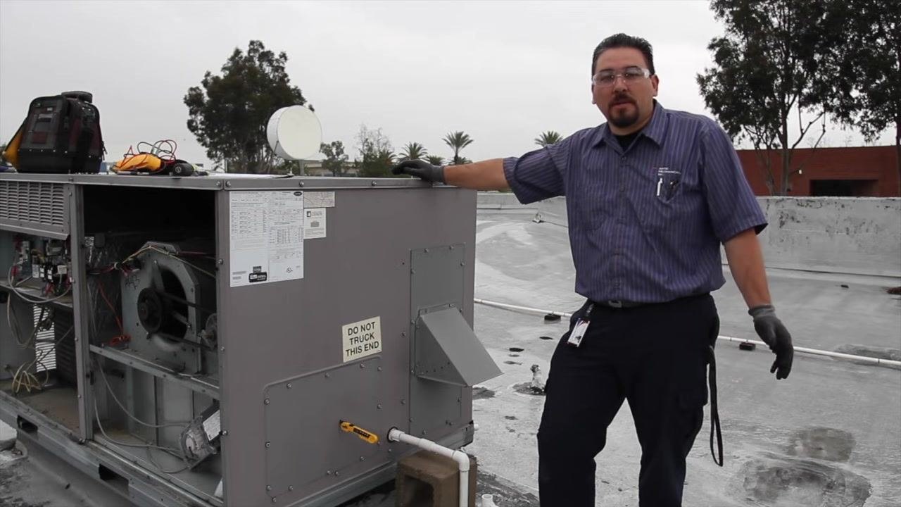
If the unit is equipped with an economizer, inspect the economizer screen. This particular unit does not have an economizer screen. For units that do have one, verify the economizer is functioning correctly, and inspect the louvers and linkage to ensure they move freely and are not obstructed. The economizer allows for free cooling by pulling in fresh air from outside when ambient temperatures are low enough.
Following these steps ensures the capacitor is functioning within specifications, the blower and pulley system is in good condition, and the economizer (if present) is operating correctly, helping maintain the efficiency and longevity of the HVAC system.
Verify economizer functionality
Confirm that the economizer, if present, is functioning correctly. Stand next to the HVAC unit with the access panels open to visually inspect the economizer components. Reference the unit's wiring diagram and specification labels, typically affixed to the exterior of the unit, for guidance.
Ensure all electrical connections and mechanical linkages associated with the economizer are intact and properly connected. Observe the economizer's operation by cycling the system or using manual controls, if available, to verify the dampers and linkages move as intended. Check for any obstructions or debris that could impede the economizer's movement.
If the economizer is not functioning, troubleshoot according to the manufacturer's instructions, checking for electrical faults, stuck dampers, or broken linkages. Document your findings and any corrective actions taken.
Verifying the economizer's operation ensures the HVAC system can utilize free cooling when conditions allow, improving energy efficiency and system performance.
Approach the unit for filter and drain maintenance
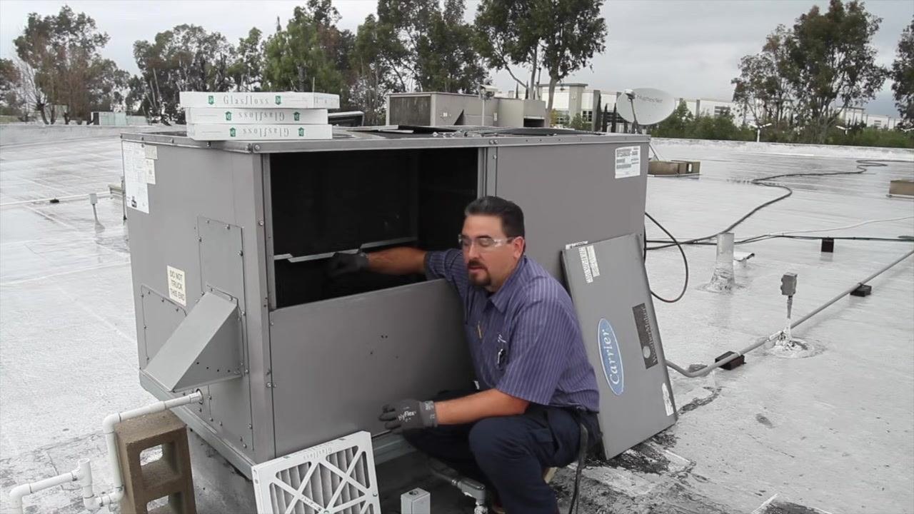
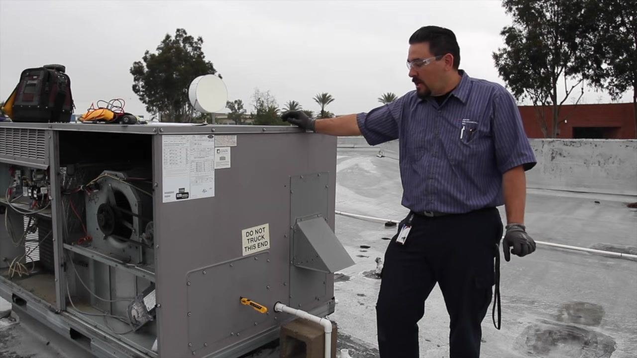
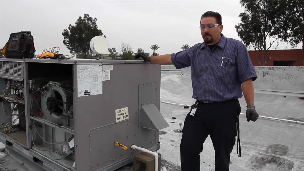
Approach the rooftop HVAC unit and ensure you are wearing appropriate safety gear, including gloves and safety glasses. This part of the checklist covers a "DO NOT TRUCK THIS END" labeled panel and the unit's internal components.
Inspect the air filters
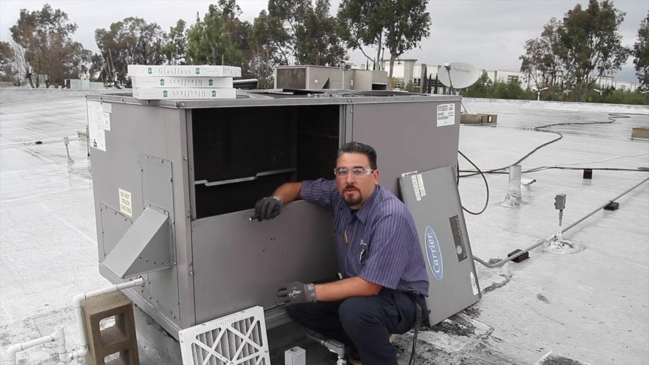
Open the access panel to expose the air filters and internal components. Inspect the air filters for dirt and debris; if the filters are dirty or clogged, prepare to replace them.
Remove the old air filters
Pull out the old filter and prepare to insert a new one in its place.
Install new air filters
Insert new air filters into the designated slots, ensuring they are properly aligned and seated.
Flush the drain pan
If the drain pan is plugged or dirty, flush the pan thoroughly to remove any blockages or buildup.
Install drain pan tablets
Install panel drain pan tablets (pan taps) to help dissolve and prevent future buildup inside the drain pan.
Clear the drain lines
Use CO2 or compressed air to blow out the drain lines, ensuring there are no clogs or obstructions.
Confirm filter installation
Confirm that the new filters are installed tightly and securely so they will not move or dislodge during operation.
Following these steps ensures the HVAC unit's filters, drains, and refrigerant system are properly maintained, helping to prevent damage and ensure efficient operation.
Attach gauges and inspect refrigerant lines
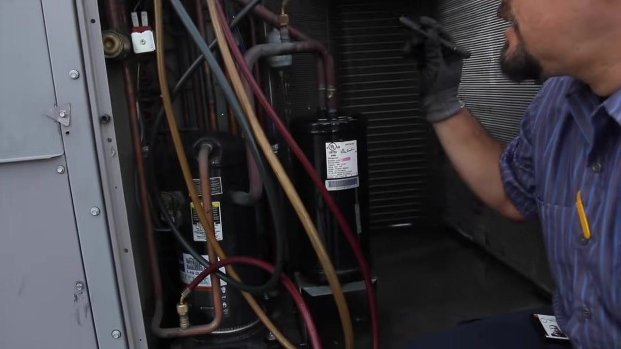
Move to the section of the unit containing the refrigerant lines and compressor. Attach pressure gauges to the service ports to check system pressures, ensuring all connections are tight.
Check fittings and connections for leaks
Check all fittings and connections for leaks using appropriate leak detection methods, and ensure all fittings are snug and secure.
Check amp draw with the unit running
With the unit running, check the amp draw of the compressor and condenser fan motor to verify proper operation.
Observe overall system operation
Observe the system for any signs of leaks, abnormal noises, or irregular operation, and address any issues found during inspection.
Energize the unit for electrical testing
Ensure the unit is powered on and operational before proceeding with electrical and performance checks.
Prepare to check amperage
Prepare to check amperage on the compressor and blower motors. Confirm that all tools and meters are ready for use before taking readings.
Open the electrical compartment for amperage testing
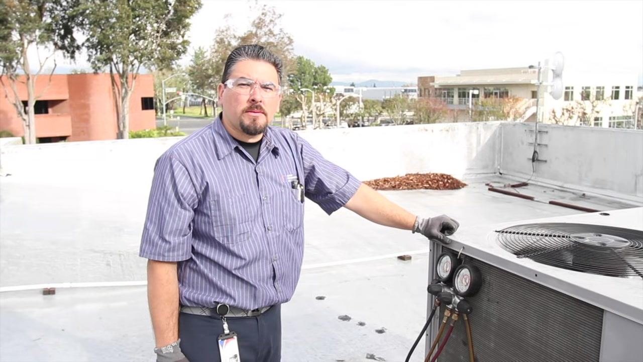
Open the access panel to expose circuit boards, relays, contactors, and wiring. Use an appropriate clamp meter to measure amperage, placing it around the wire leading to the compressor.
Measure the compressor amperage
Clamp the meter around the compressor wire and observe and record the amperage reading.
Measure the blower motor amperage
Move the clamp meter to the blower motor wire, observe and record the amperage reading. A lower amp reading is expected when the blower is running less hard.
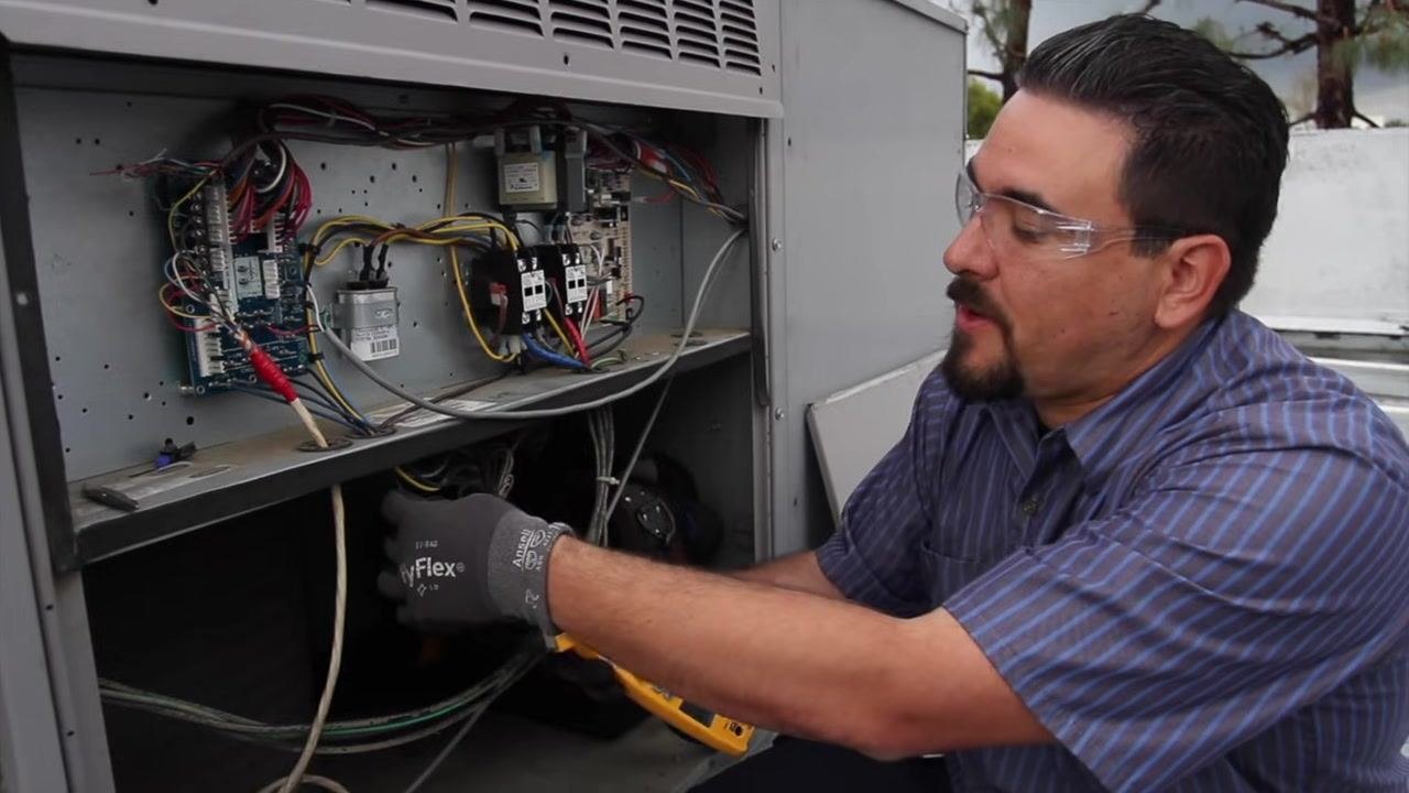
Check the condenser fan motor amperage
Position the clamp meter around the condenser fan motor wire and take the measurement.
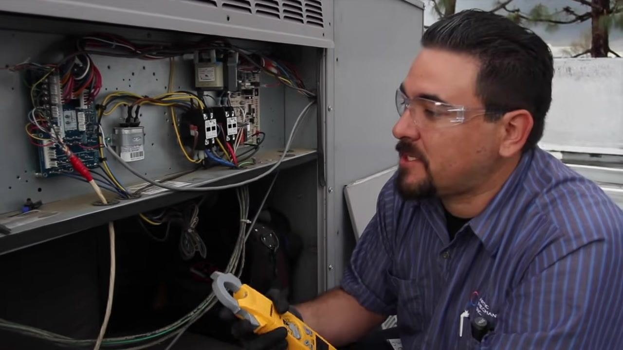
Record the condenser fan motor amperage
Record the reading; in this case, the condenser fan motor is running at 1.5 amps. Compare this value to the manufacturer's specifications to confirm proper operation.

Decide on component replacement if necessary
If amperage readings are outside normal range or performance is suboptimal, plan to replace faulty components. In this case, the capacitor is identified for replacement due to performance issues.
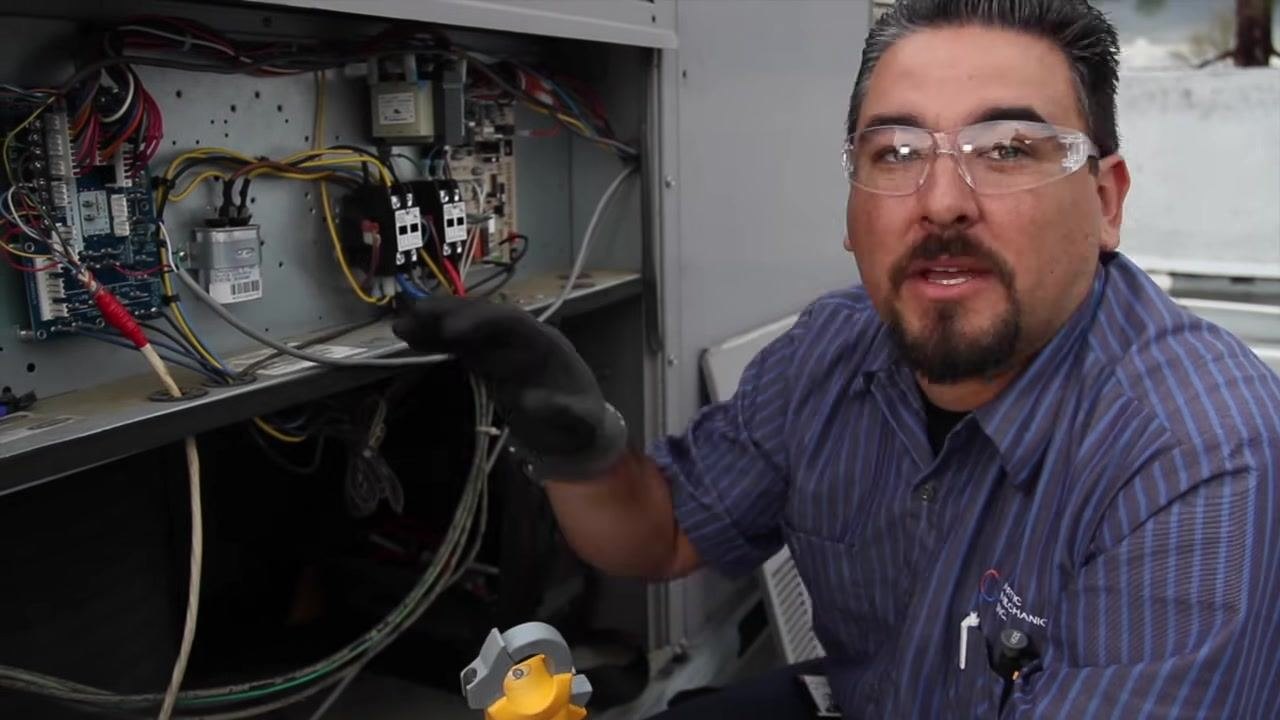
Measure the supply air temperature
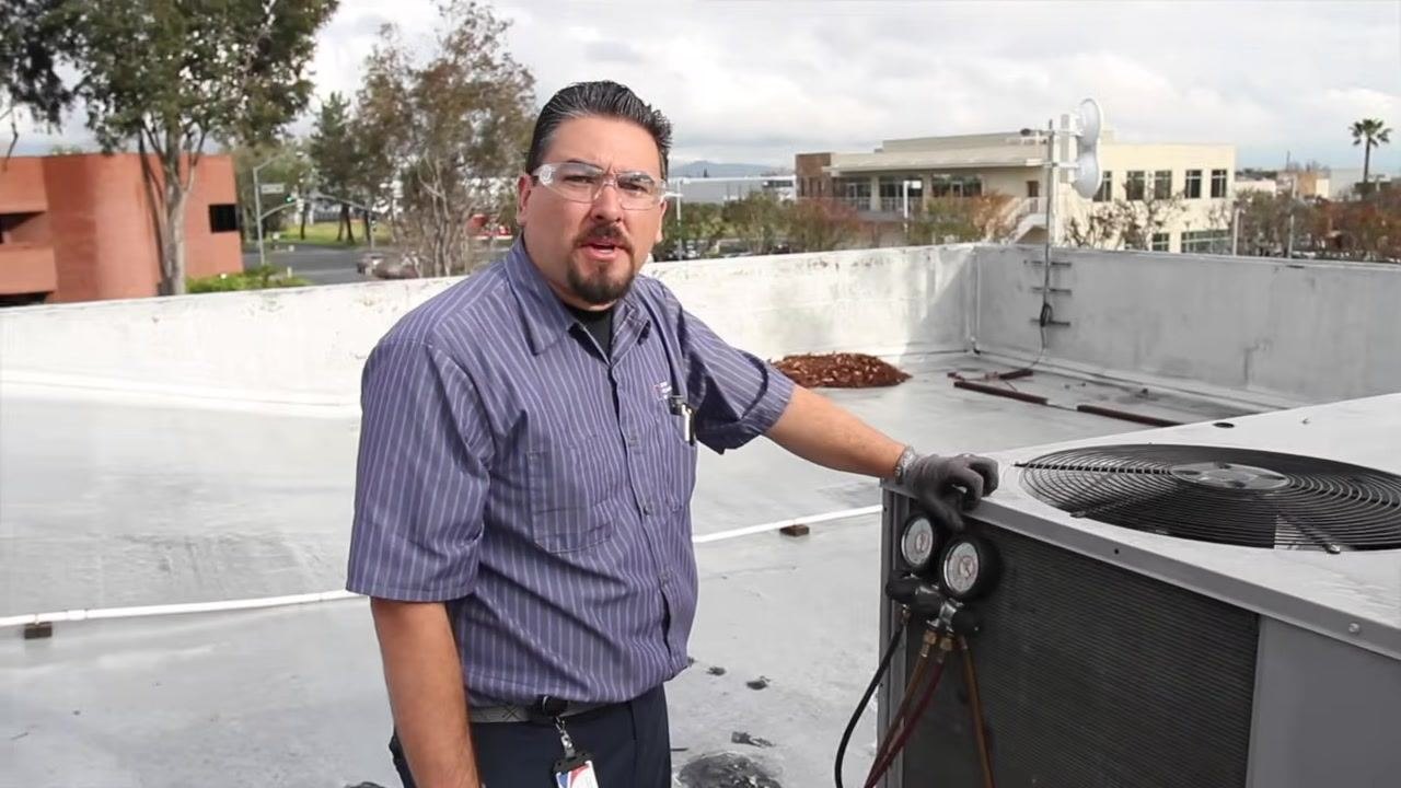
Identify the supply vent on the HVAC unit, labeled "DO NOT TRUCK THIS END." Use a digital thermometer or temperature probe to measure the supply air temperature.
Measure the return air temperature
Move to the return air section of the unit, often labeled with the manufacturer's name (for example, "WeatherMaker"). Use the same digital thermometer or probe to measure the return air temperature. In this case, the return temperature reading is 66°F.
Calculate the temperature differential
Note the supply temperature (46°F) and the return temperature (66°F). Subtract the supply temperature from the return temperature to determine the temperature drop across the coil (ΔT = 66°F − 46°F = 20°F). Ensure the temperature differential is within the manufacturer's recommended range for efficient operation.
Following these steps completes the electrical, airflow, and temperature performance checks necessary for comprehensive rooftop HVAC unit maintenance, ensuring the system operates safely, efficiently, and within manufacturer specifications.
Restore power to the unit
Ensure all maintenance and testing procedures are complete and all tools are removed from the unit. Locate the electrical disconnect box mounted on the side of the HVAC unit and turn the disconnect switch back to the "ON" position to restore power to the equipment.
Verification and summary
This HVAC preventive maintenance checklist covers power verification, coil cleaning, electrical component inspection, capacitor and blower testing, economizer verification, filter and drain servicing, refrigerant system inspection, amperage testing, and temperature differential checks. Confirm that:
- All electrical connections and terminals are tight and free of pitting or wear.
- The capacitor reading falls within the manufacturer's specified microfarad range.
- Air filters are new, properly seated, and secure.
- The drain pan and drain lines are clear of blockages.
- Refrigerant fittings show no signs of leaks.
- Compressor, blower, and condenser fan motor amperage readings match manufacturer specifications.
- The temperature differential across the coil falls within the recommended range.
- Power has been fully restored to the unit before ending the service call.
Always remember to restore power after servicing and to complete documentation of any parts replaced or issues found during the inspection.
Generation details: cost, quality tiers
Docsie billed 4,500 credits ($3.15) to analyze this 9-minute video at standard quality. The rewrite, template fill and Word/PDF exports were included. The same video at each quality tier:
| Quality | Frames sampled | Credits | Approx. cost |
|---|---|---|---|
| Draft | every 16-30 s | 2,250 | $1.57 |
| Standard (this guide) | every 8-15 s | 4,500 | $3.15 |
| Detailed | every 4-7 s | 9,000 | $6.30 |
| Ultra | every 1-3 s | 18,000 | $12.60 |
Credits priced at $0.70 per 1,000; plans include a monthly allowance. Enterprise customers on on-premise or bring-your-own-model deployments run this on their own inference and pay no per-video credits.
Generated by Docsie Video-to-Docs on 2026-09-10 from a 8-minute video. Screenshots are frames from the source video and belong to their creator, Sami Ayyat, whose original is embedded above. If you own this video and want the guide removed or credited differently, contact us and we will act within one business day.