
How to Use Feeler Gauges
This procedure explains how to use feeler gauges (also known as feeler blades) to accurately measure clearances between engine components, such as valve lash on a cylinder head. You will learn how to select the correct blade thickness, develop a proper sense of "feel" for resistance, and confirm your measurement against a known specification.
Video: How To Use A Feeler Gauge/Feeler Blade | Performance Engine Building [FREE LESSON] by High Performance Academy (2018). All credit for the demonstration goes to the creator; watch the original on YouTube. The written guide below was generated from this video by Docsie. Creator? Request a change or removal.
This procedure explains how to use feeler gauges (also known as feeler blades) to accurately measure clearances between engine components, such as valve lash on a cylinder head. You will learn how to select the correct blade thickness, develop a proper sense of "feel" for resistance, and confirm your measurement against a known specification.
Purpose
This SOP provides step-by-step guidance on how to use feeler gauges correctly when measuring clearances on engine components. It covers selecting the right blade, understanding the resistance you should feel, and applying the technique to a real-world example: measuring valve lash clearance on a Toyota 1FZ cylinder head.
Scope
This procedure applies to any situation requiring precise clearance measurement on engine components using a feeler gauge set, including camshaft and valve train clearances. The example in this SOP demonstrates the technique on the exhaust valve of cylinder number one on a Toyota 1FZ cylinder head.
Required equipment
- A standard feeler gauge set with hardened steel blades
- Blades marked with thickness in both metric (mm) and imperial (inch) units
- A Toyota 1FZ cylinder head (or other engine component to be measured), mounted on a stable workbench
- Two glossy magazines and a sheet of A4 printer paper (for the resistance practice exercise)
Step-by-step procedure
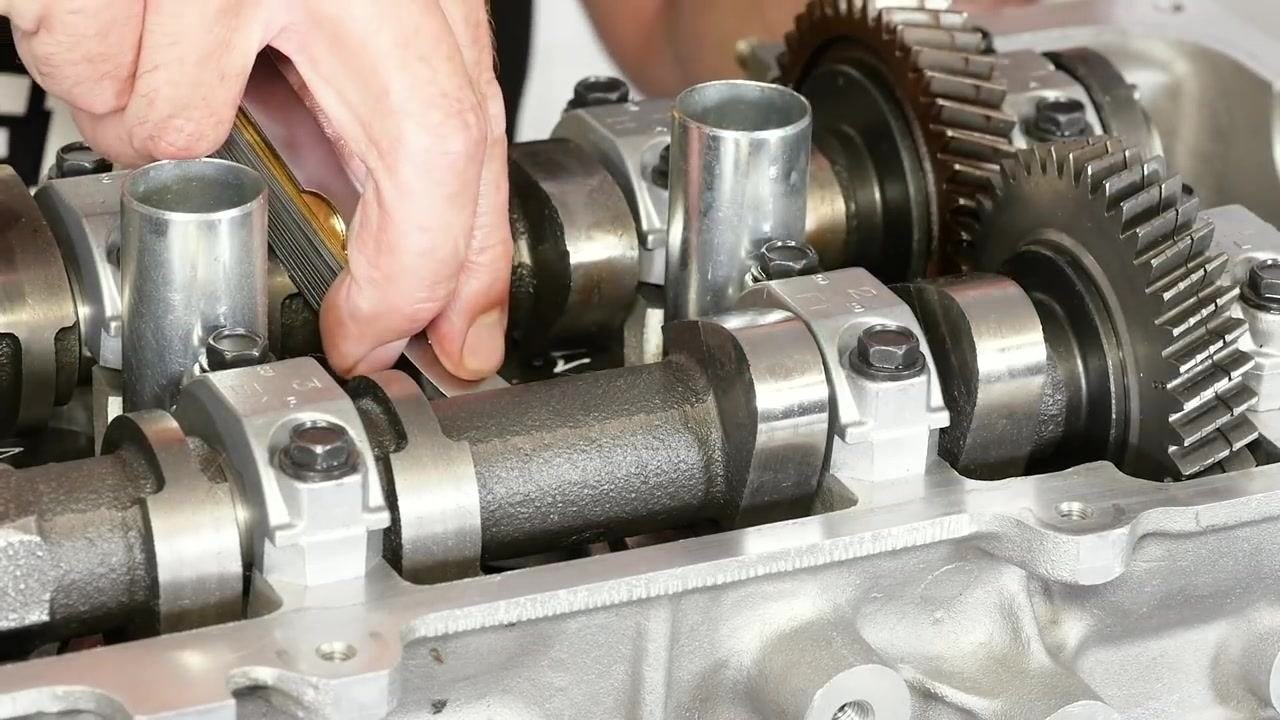
Gather your feeler gauge set
Collect a standard feeler gauge set that includes a range of hardened steel blades. Confirm the set is complete and in good condition before use.
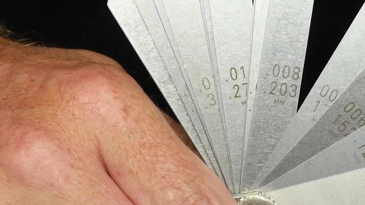
Inspect the thickness markings
Open the set and check the markings on each blade to identify its thickness. Confirm that both metric and imperial units are marked, so you can work in your preferred measurement system.
Understand the concept of resistance
Proper use of feeler gauges depends on knowing the expected resistance as you slide a blade through the gap being measured. A blade that is too thin produces no friction or resistance. A blade that is too thick can be forced through but will meet significant resistance.
Practice sensing correct resistance
Before measuring real components, build a feel for correct resistance using a simple exercise: place a sheet of A4 printer paper between two glossy magazines and hold down the corner of the magazines to keep them steady.

Perform the resistance test
Gently pull the sheet of paper out from between the magazines while holding them down. Note the amount of resistance you feel — this simulates the resistance you should expect when using the correct-thickness feeler gauge.
Note the safety reminder for oversized blades
If you use a feeler gauge that is too large for the gap, you will feel noticeably more resistance than in the paper test. Never force an oversized blade into a clearance, as this can produce an inaccurate reading or damage components.

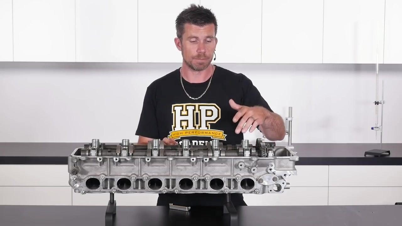
Prepare the cylinder head for measurement
Set up the Toyota 1FZ cylinder head on a stable workbench. For this example, identify the exhaust valve on cylinder number one as the point to be measured.
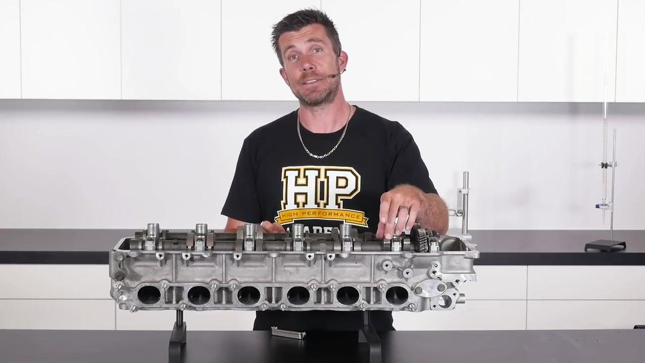
Locate the measurement point
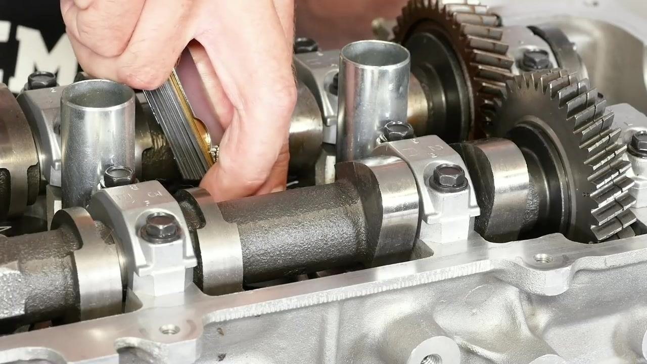
Find the base circle of the camshaft lobe and the bucket (lifter) it sits on. This is the location where you will insert the feeler gauge to measure the clearance.
Select and insert the initial feeler gauge
For this type of mechanical valve mechanism, a typical cold clearance is about 0.010 inches (10 thousandths of an inch). Select the 0.010 inch feeler gauge and carefully slide it between the base circle of the camshaft and the top of the bucket or lifter.
- If the blade slides through with absolutely no resistance, the clearance is larger than 0.010 inches and the blade is too small for an accurate reading.
Step up to the next blade size
Select the next size up, a 0.012 inch (12 thou) feeler gauge, and repeat the insertion at the same measurement point.
- If you feel a reasonable amount of resistance with the 0.012 inch blade, this likely matches the actual clearance.
Verify with the next size up
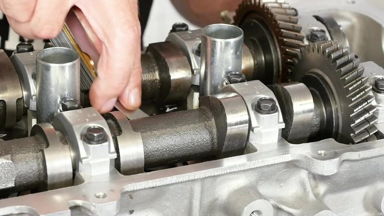
To confirm your reading, try inserting a 0.013 inch (13 thou) feeler gauge at the same location.
- If the 0.013 inch blade does not fit, or fits only with excessive resistance, the actual clearance is approximately 0.012 inches.
- Do not force the blade; excessive resistance means the blade is too thick for an accurate measurement.
Confirm the final clearance reading
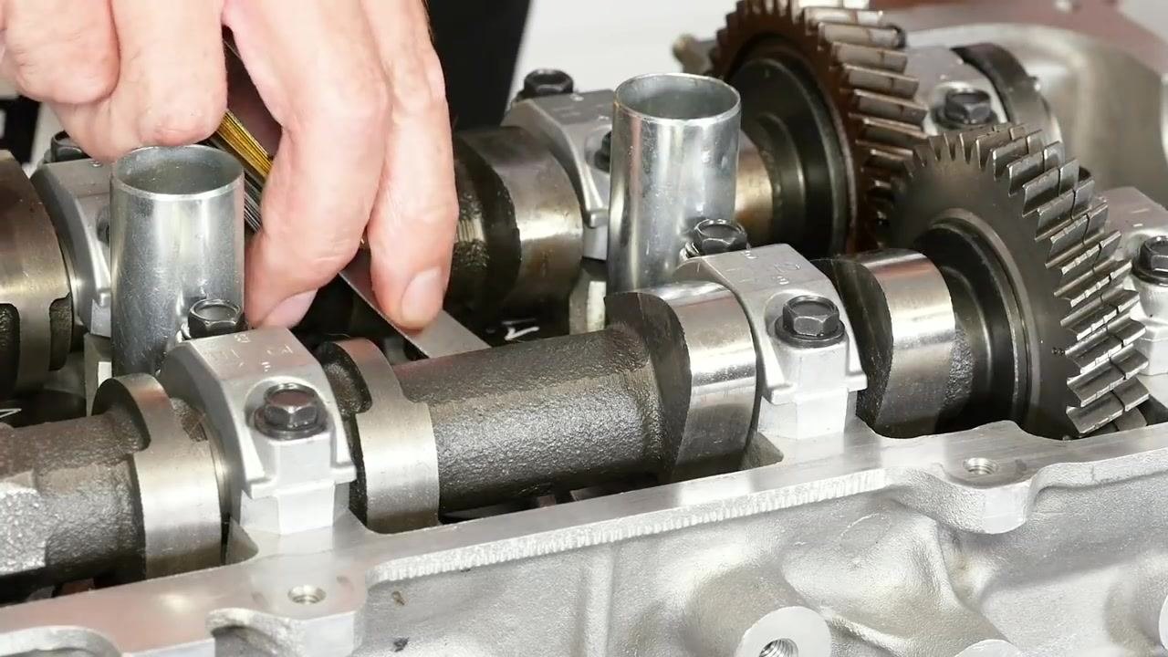
Return to the 0.012 inch (12 thou) feeler gauge and attempt to insert it between the camshaft and the bucket. If it requires a reasonable amount of effort to insert, this confirms the clearance is correct — in this example, 0.012 inches.
Verification and summary
To confirm you have used the correct feeler gauge:
- Confirm the blade fits with a reasonable, moderate amount of resistance — not free-sliding and not forced.
- Confirm the next size up either does not fit or fits only with excessive resistance.
- Record the confirmed measurement for reference.
Developing an accurate feel for feeler gauge resistance takes practice. With experience, you will quickly recognize the correct amount of resistance when checking clearances on any engine component.
What's next
For a deeper understanding of engine assembly and measurement techniques, consider further training in engine building. Relevant topics include:
- Engine anatomy
- Essential engine machining processes
- How to select and measure critical clearances
- Engine long block assembly
- Procedures for breaking in a fresh engine
Generation details: cost, quality tiers
Docsie billed 2,500 credits ($1.75) to analyze this 5-minute video at standard quality. The rewrite, template fill and Word/PDF exports were included. The same video at each quality tier:
| Quality | Frames sampled | Credits | Approx. cost |
|---|---|---|---|
| Draft | every 16-30 s | 1,250 | $0.88 |
| Standard (this guide) | every 8-15 s | 2,500 | $1.75 |
| Detailed | every 4-7 s | 5,000 | $3.50 |
| Ultra | every 1-3 s | 10,000 | $7.00 |
Credits priced at $0.70 per 1,000; plans include a monthly allowance. Enterprise customers on on-premise or bring-your-own-model deployments run this on their own inference and pay no per-video credits.
Generated by Docsie Video-to-Docs on 2026-09-09 from a 4-minute video. Screenshots are frames from the source video and belong to their creator, High Performance Academy, whose original is embedded above. If you own this video and want the guide removed or credited differently, contact us and we will act within one business day.