
How to Read Welding Symbols
This SOP explains how to read welding symbols by walking through the fundamental elements every welder needs to recognize: the reference line, the arrow, the tail, and the fillet weld symbol. The session is led by the Director of Training at Tulsa Welding School and focuses only on the most basic welding symbols, not advanced or complex ones. Following these steps will help you correctly identify weld size, length, pitch, and placement from a diagram.
Video: Basics of Welding Symbols ~ Tulsa Welding School by Tulsa Welding School (2021). All credit for the demonstration goes to the creator; watch the original on YouTube. The written guide below was generated from this video by Docsie. Creator? Request a change or removal.
Purpose
This SOP explains how to read welding symbols by walking through the fundamental elements every welder needs to recognize: the reference line, the arrow, the tail, and the fillet weld symbol. The session is led by the Director of Training at Tulsa Welding School and focuses only on the most basic welding symbols, not advanced or complex ones. Following these steps will help you correctly identify weld size, length, pitch, and placement from a diagram.
Scope
This procedure covers the basic components of a welding symbol as demonstrated on a training whiteboard, including how to read fillet weld symbols, intermittent weld notations, arrow-side versus other-side placement, and an introduction to advanced elements such as circles, flags, tails, and contour/finish notations. It does not cover complex or advanced welding symbols in full depth; those are addressed in later sessions.
Prerequisites
- Access to the whiteboard training session where welding symbols and notes are displayed.
- Paper and a pen or pencil to copy down notes and symbols for future reference, if needed.
- Basic familiarity with the classroom/training room setup, where two instructors present symbols and diagrams on a whiteboard.
No specific personal protective equipment is referenced for this classroom session, as it focuses on symbol interpretation rather than hands-on welding.
Procedure
Step 1: Review the whiteboard for notes and symbols
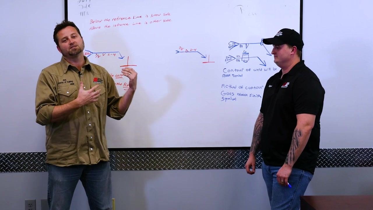
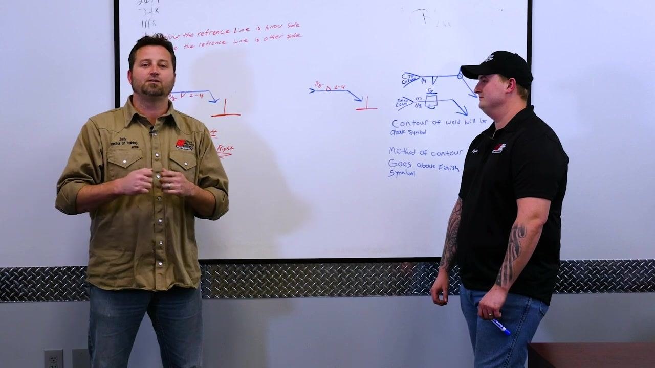
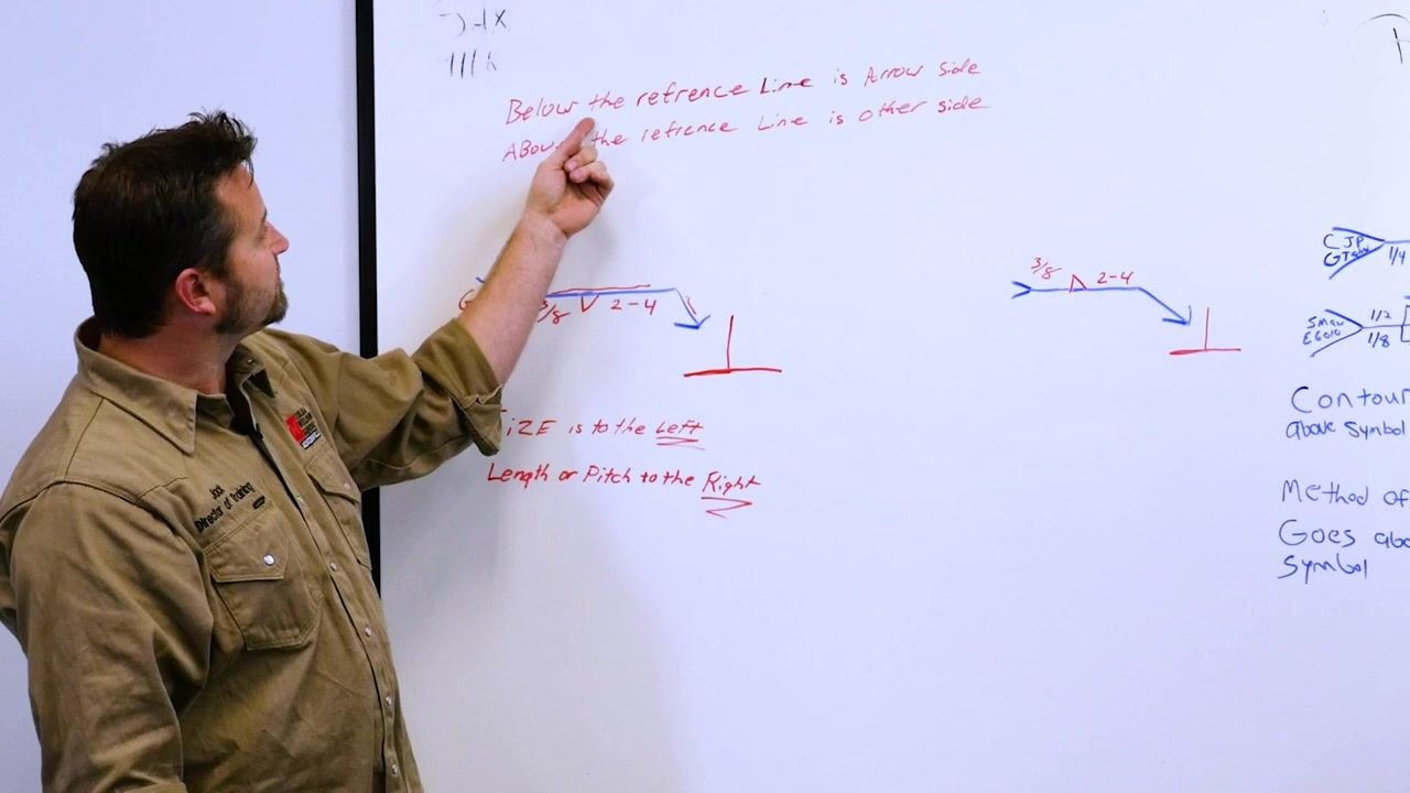
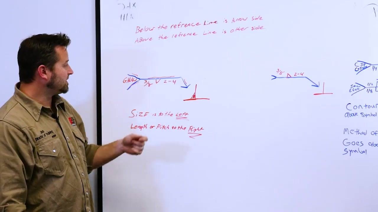
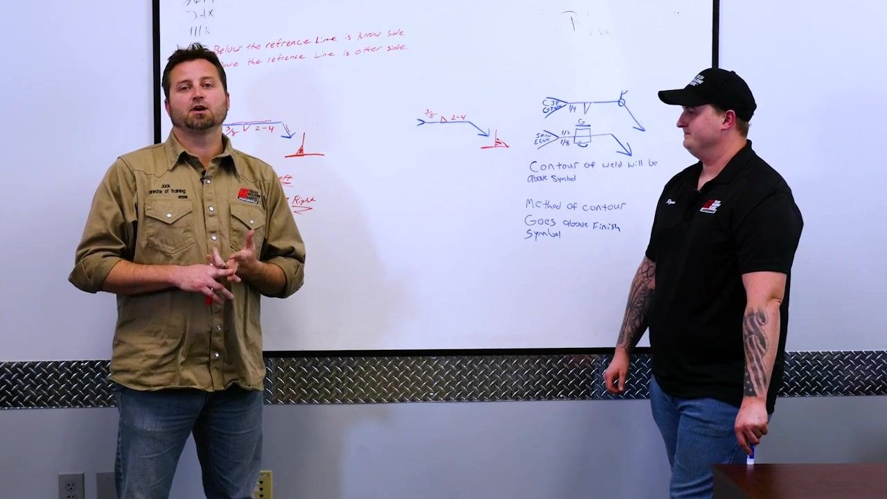
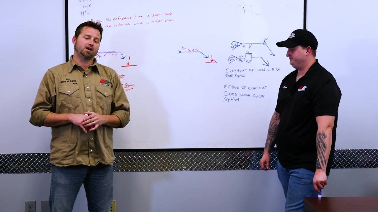
Observe the whiteboard where several welding symbols and notes are drawn and written in red and blue marker. If needed, pause to copy down the notes for future reference. The instructor acknowledges that the handwriting and drawings may not be perfect but are sufficient for learning the basics.
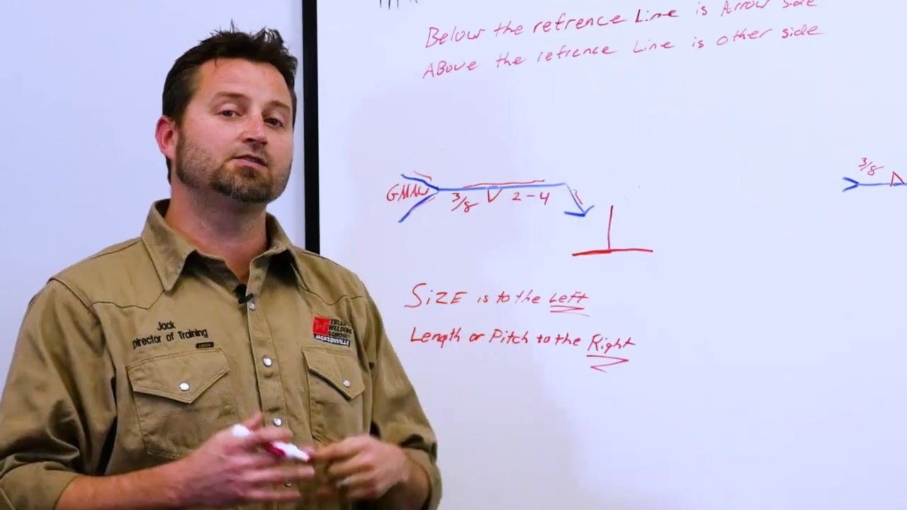
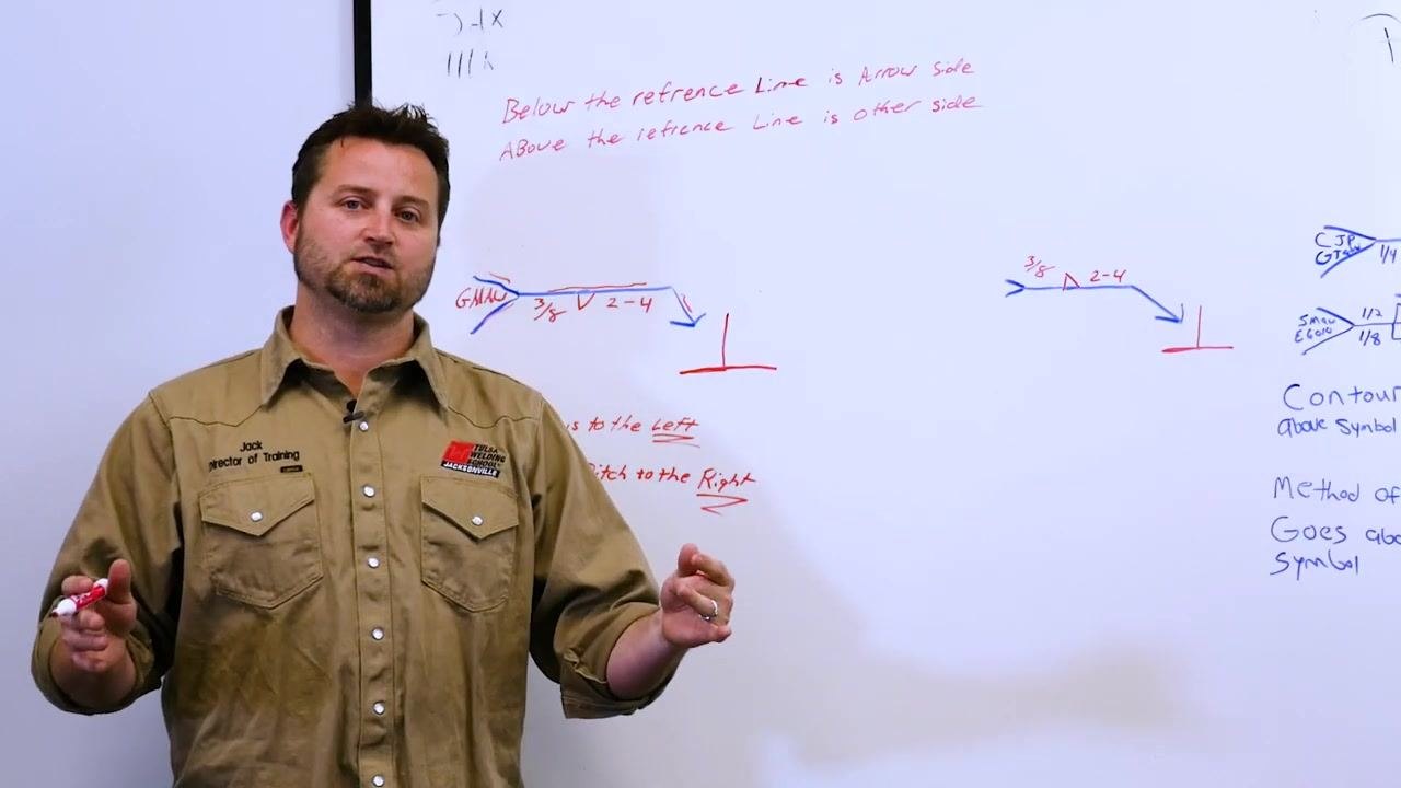
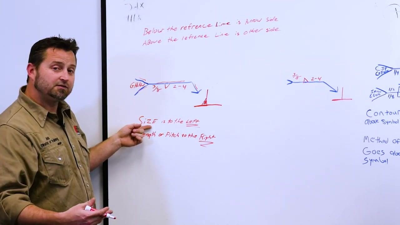
Key visible notes on the board include: - "Below the reference line is arrow side" - "Above the reference line is other side" - "SIZE is to the left" - "Length or Pitch to the Right" - Various welding symbols and arrows, with labels such as "GMAW", "3/8", "2-4", and a triangle symbol.
Step 2: Identify the main components of a welding symbol
Locate the reference line on the welding symbol, shown as a horizontal blue line on the board. Identify the arrow, which points to the location of the weld, and the tail, which contains additional information such as the welding process or joint completion status. In the example shown, the tail contains "GMAW", which stands for Gas Metal Arc Welding, commonly known as MIG welding. The reference line, arrow, and tail are the foundational elements of a welding symbol.
Step 3: Understand the information in the tail
The tail may specify the welding process (for example, GMAW for Gas Metal Arc Welding/MIG welding), whether the weld is to be completed, partially completed, or fully welded, and other relevant instructions for the weld.
Step 4: Recognize the fillet weld symbol
The triangle symbol on the reference line represents a fillet weld. When you see the triangle, it indicates that a fillet weld is required. This session focuses only on the fillet weld symbol for simplicity.
Step 5: Interpret the placement of size and length information
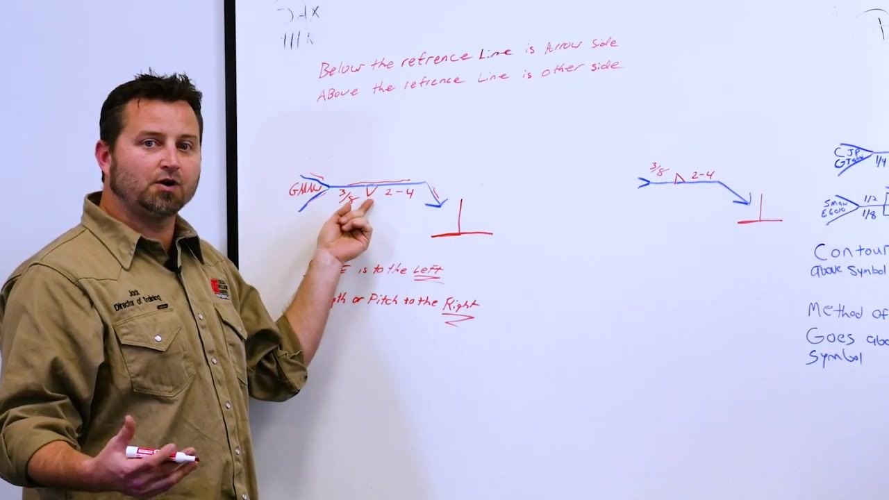
The size of the weld is indicated to the left of the fillet weld symbol (triangle), while the length or pitch of the weld is indicated to the right of the symbol. In the example from the board, "3/8" appears to the left of the triangle and "2-4" appears to the right.
Step 6: Determine the size of the weld
Identify the number to the left of the fillet weld symbol (triangle) on the reference line. In the example, "3/8" is written to the left of the triangle, indicating that the leg length of the fillet weld should be 3/8 inch, with both legs measuring 3/8 inch.
Step 7: Interpret the length and pitch for intermittent welds
Locate the numbers to the right of the fillet weld symbol (triangle). In the example, "2-4" is written to the right of the triangle, meaning the weld is intermittent: weld 2 inches, skip 2 inches, for every 4 inches along the joint, measured center to center. This is called an "intermittent weld." The first number represents the length of each weld segment, and the second number is the pitch — the distance from the start of one weld segment to the start of the next.
Step 8: Determine weld side placement
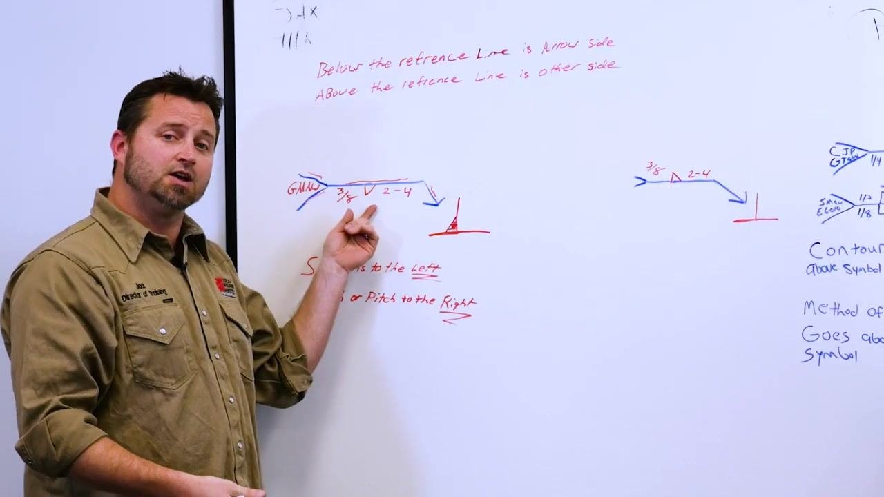
Review the position of the fillet weld symbol relative to the reference line. If the symbol is below the reference line, the weld is placed on the arrow side of the joint. If the symbol is above the reference line, the weld is placed on the other side of the joint. The board notes state: "Below the reference Line is Arrow Side. Above the reference Line is Other Side." In the example, the triangle is below the reference line, so the weld is to be made on the arrow side.
Step 9: Apply the arrow side rule to the example
Confirm that the fillet weld symbol is below the reference line in the example. As the note is applied to this symbol, the intermittent fillet weld that is 3/8 inch is placed on the arrow side of the joint. In the field, place the weld on the side of the joint indicated by the arrow.
Step 10: Summarize the example weld symbol
The weld to be made is a fillet weld, 3/8 inch in size, placed intermittently — 2 inches of weld every 4 inches — on the arrow side of the joint.
Step 11: Reinforce the placement of size and length/pitch information
The size of the weld (for example, "3/8") is always to the left of the welding symbol. The length or pitch (for example, "2-4") is always to the right of the welding symbol, as reinforced by the notes "SIZE is to the left" and "Length or Pitch to the Right."
Step 12: Prepare for a second example
Transition to a second example, where the same process will be repeated with a similar symbol. The classroom environment remains the same, with a whiteboard, visible welding symbols, and clear instructional notes.
Step 13: Review weld placement for the second example
Confirm that the weld size and length remain unchanged from the previous example. In this second example, the weld symbol is above the reference line, meaning the weld is placed on the other side of the joint rather than the arrow side, per the note "Above the reference Line is Other Side."
Step 14: Identify elements of an advanced symbol
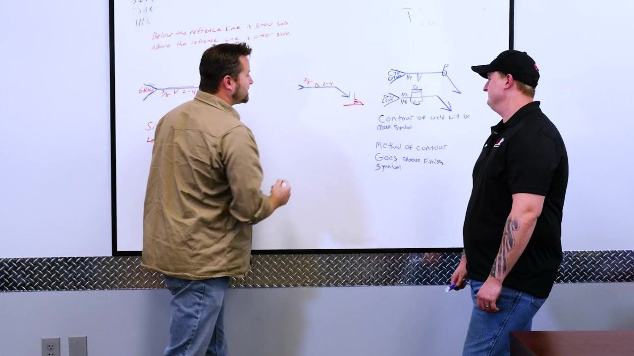
A second instructor demonstrates a more detailed welding symbol that introduces the tail and arrow point in greater depth. Observe the new welding symbol drawn on the whiteboard:
- It is a fillet weld, indicated by the triangle symbol, on the arrow side.
- The specified weld size is 1/4 inch.
- A circle appears at the intersection of the reference line and arrow.
- A flag is present at the end of the reference line.
- The tail contains the notations "CJP" and "GTAW."
These elements mean the following: the circle indicates the weld should go all the way around; the flag indicates a field weld, to be welded on site; "CJP" stands for Complete Joint Penetration; and "GTAW" (Gas Tungsten Arc Welding) indicates the TIG welding process.
Step 15: Interpret the advanced welding symbol
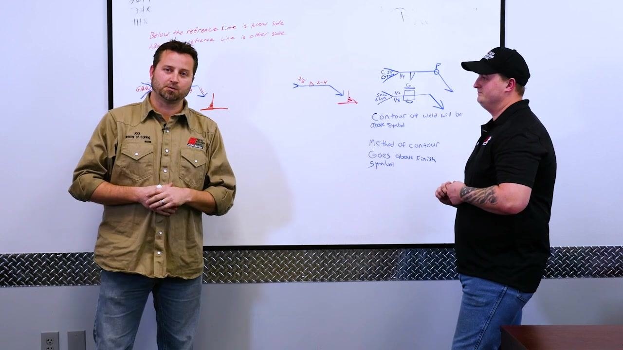
Based on the elements identified, make a 1/4-inch fillet weld on the arrow side of the joint, weld the joint all the way around as indicated by the circle, and perform the weld in the field as indicated by the flag. Ensure the weld achieves complete joint penetration (CJP), using the GTAW (TIG) welding process.
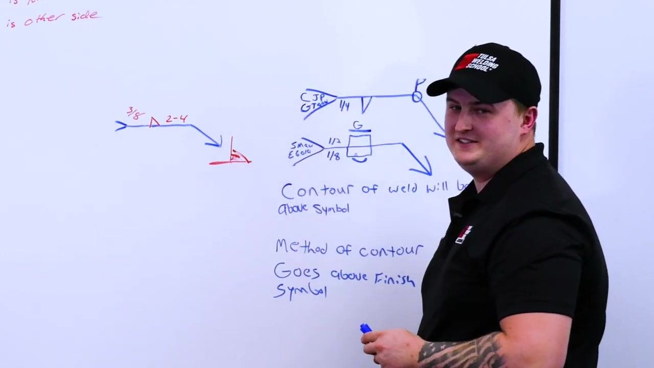
Step 16: Analyze slot weld symbols and contour notes
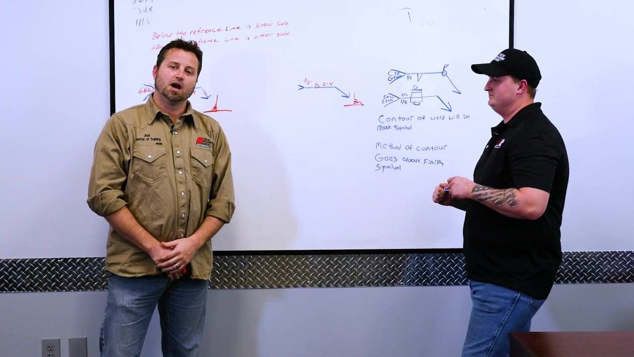
Examine a third symbol that has notations on both sides of the reference line — arrow side and other side. Identify the slot weld symbols: one slot is specified as 1/2 inch, and the other as 1/8 inch, indicating welds on both sides of the joint. Also observe the contour and finish notes on the board:
- "Contour of weld will be above symbol"
- "Method of contour goes above finish symbol"
Step 17: Summarize the interpretation of advanced symbols
For the first advanced symbol: make a 1/4-inch fillet weld on the arrow side, weld all the way around, perform the weld in the field, and achieve complete joint penetration using GTAW (TIG). For the second symbol: place slot welds of 1/2 inch and 1/8 inch on both sides of the joint, and follow the contour and finish instructions indicated above the symbols.
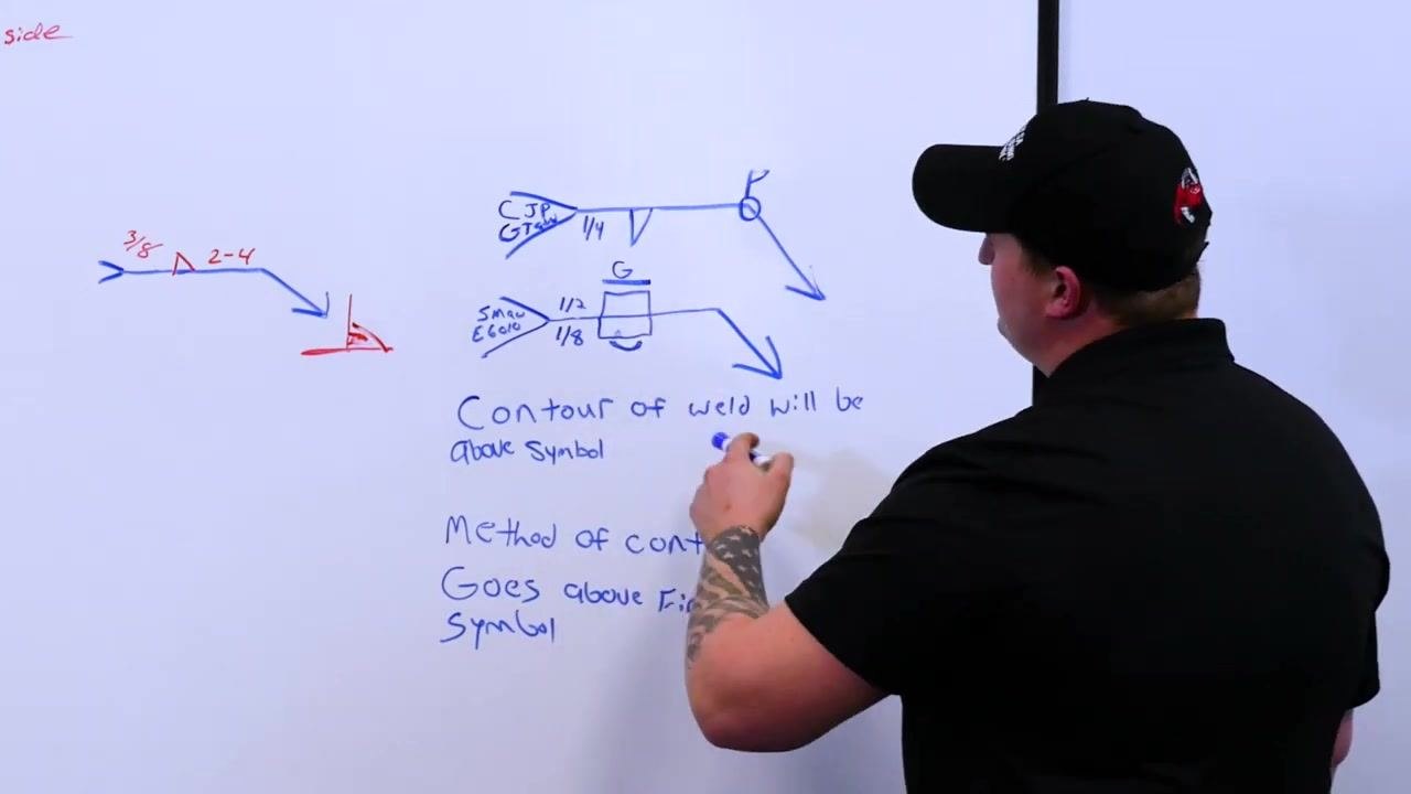
Step 18: Interpret contour and finish symbols
Identify the key welding symbols on the board: a fillet weld symbol with a triangle and "3/8," "2-4" notations; an advanced symbol with a circle (weld all around), flag (field weld), tail labeled "CJP" and "GTAW," and a "1/4" weld size; and slot weld symbols with "1/2" and "1/8" notations, plus a "G" above the slot symbol.
The handwritten instructions read: "Contour of weld will be above symbol" and "Method of contour goes above finish symbol." For this example, a flat or flush weld contour is required, and it must be achieved by grinding. When reading welding symbols, always check above the symbol for contour instructions, and look above the finish symbol for the method used to achieve that contour. If "G" is present, use grinding to achieve the flat or flush finish.
Step 19: Review the recap of welding symbols and notes
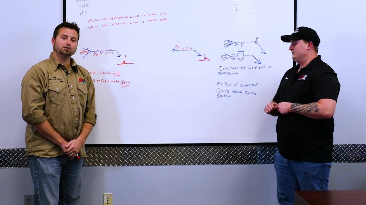
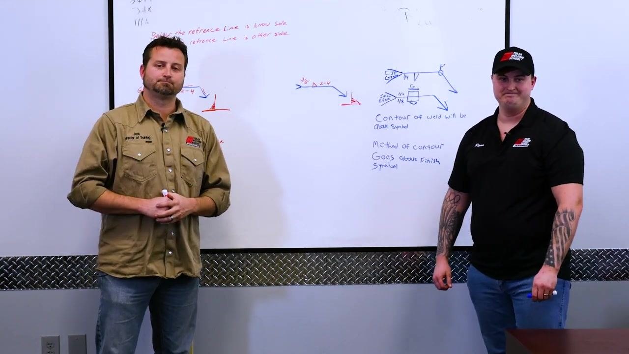
In the recap portion of the session, observe the whiteboard displaying various welding symbols, arrows, and notations in red and blue marker, including:
- "Contour of weld will be above symbol"
- "Method of contour goes above finish symbol"
- Symbols and notations such as "3/8", "2-4", "CJP", "GMAW", "SMAW E6010", "1/2", and "1/8", along with graphical weld symbols.
Step 20: Confirm the scope of the lesson
This portion of the session is a recap of the basic welding symbols covered so far. Both instructors are present, standing on either side of the whiteboard in the classroom or training room, which has metal paneling along the wall.
Step 21: Reconfirm that only basic symbols were covered
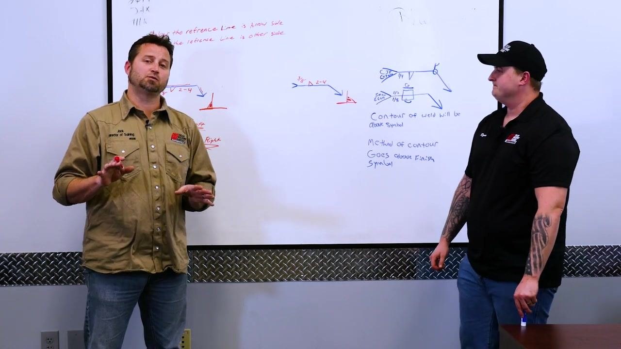
Only the basic welding symbols have been covered in this session. Both instructors remain engaged at the whiteboard, which continues to serve as the central teaching aid displaying all relevant symbols and notes.
Step 22: Note the placement of symbols above the reference line
Certain symbols or information will be placed above the reference line in welding diagrams, as reinforced during the recap.
Verification and summary
To confirm you can correctly read a basic welding symbol, check that you have:
- Identified the reference line, arrow, and tail.
- Recognized the triangle as the fillet weld symbol.
- Located the weld size to the left of the symbol and the length/pitch to the right.
- Determined whether the weld goes on the arrow side (symbol below the reference line) or the other side (symbol above the reference line).
- Recognized additional elements such as circles (weld all around), flags (field weld), and tail notations for process and penetration requirements (for example, CJP, GTAW, GMAW).
- Checked above the symbol for contour instructions and above the finish symbol for the method used to achieve that contour (for example, "G" for grinding).
Always refer to written notes and full symbol details for precise execution in the field.
What's next
More advanced welding symbols and concepts will be covered in subsequent sessions, building on the basic reference line, arrow, tail, and fillet weld symbol foundations established in this SOP.
Generation details: cost, quality tiers
Docsie billed 3,500 credits ($2.45) to analyze this 7-minute video at standard quality. The rewrite, template fill and Word/PDF exports were included. The same video at each quality tier:
| Quality | Frames sampled | Credits | Approx. cost |
|---|---|---|---|
| Draft | every 16-30 s | 1,750 | $1.22 |
| Standard (this guide) | every 8-15 s | 3,500 | $2.45 |
| Detailed | every 4-7 s | 7,000 | $4.90 |
| Ultra | every 1-3 s | 14,000 | $9.80 |
Credits priced at $0.70 per 1,000; plans include a monthly allowance. Enterprise customers on on-premise or bring-your-own-model deployments run this on their own inference and pay no per-video credits.
Generated by Docsie Video-to-Docs on 2026-09-09 from a 6-minute video. Screenshots are frames from the source video and belong to their creator, Tulsa Welding School, whose original is embedded above. If you own this video and want the guide removed or credited differently, contact us and we will act within one business day.