
How to Read a Welding Blueprint
This procedure explains how to read a welding blueprint by identifying the standard line types and view layouts used in orthographic projection drawings. Following these steps builds the foundation you need to interpret technical prints accurately for welding and metal fabrication work.
Video: BLUEPRINT READING FOR WELDERS AND METAL FABRICATORS 1 by hanging with heavy (2019). All credit for the demonstration goes to the creator; watch the original on YouTube. The written guide below was generated from this video by Docsie. Creator? Request a change or removal.
This procedure explains how to read a welding blueprint by identifying the standard line types and view layouts used in orthographic projection drawings. Following these steps builds the foundation you need to interpret technical prints accurately for welding and metal fabrication work.
Purpose
This SOP teaches you how to read a welding blueprint by recognizing the basic line types, understanding the three standard orthographic views, and checking a print for completeness before fabrication begins.
Scope
This procedure applies to welders and metal fabricators who need to interpret shop drawings, including orthographic projection prints showing Top/Plan, Front, and Right Side views.
Requirements
- A sample blueprint or print showing orthographic views
- Note-taking materials to record line types and dimensions
- No special PPE is required for this reading exercise, since it is a classroom-style review of a print rather than a hands-on shop task
Learn the three basic line types
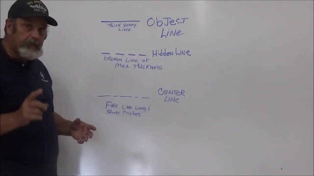
Start by learning the three essential lines used on every blueprint:
- Object Line: a thick, heavy, dark line that shows the outside shape of an object or a hole
- Hidden Line: a broken line of medium thickness, shown as a series of dashes, indicating a feature that is not visible from the current view but is still present
- Center Line: a fine line with alternating long and short dashes, showing the center of an object such as a tank, a hole, or the location of a feature
Understand the function of each line
Once you can identify the three line types, learn what each one tells you:
- The Object Line outlines the visible edges and boundaries of the part.
- The Hidden Line alerts you to features that are not visible but must still be accounted for.
- The Center Line helps you locate the center of objects or features for accurate fabrication.
Learn the three standard orthographic views
Learn orthographic projection, the standard method for showing a three-dimensional object in two dimensions using three main views:
- Top or Plan View
- Front View
- Right Side View
Note that blueprints may also include a Left Side View or a Bottom View when needed to fully describe the part.
Identify labeled lines on a sample print
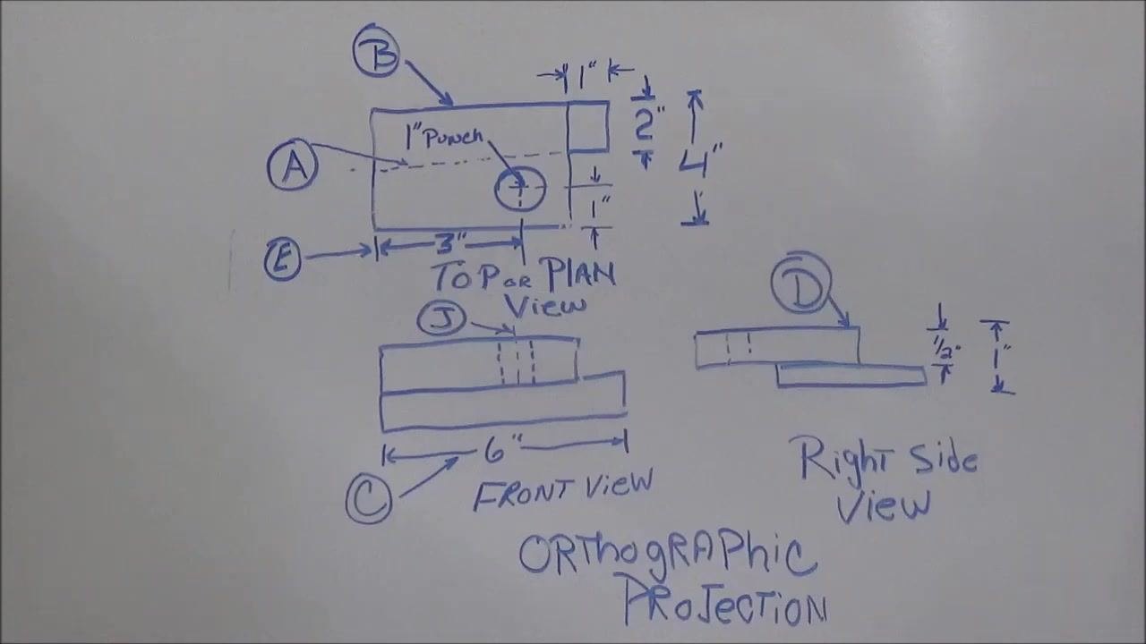
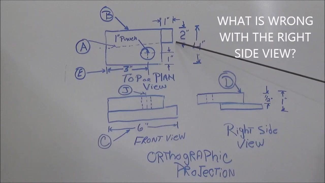
Examine a sample blueprint with labeled lines (A, B, C, D, E) across the three main views, and match each label to its line type:
- A – Hidden Line: a feature, such as a hole or material, that passes through the object but is not visible from the current view.
- B – Object Line: a thick, heavy line showing the outside shape of the object or a hole.
- C – Dimension Line: a line indicating a measurement, for example "6 inches from this point to this point."
- D – Object Line: like B, a thick line showing the outside shape of the object.
- E – Extension Line: a line that extends the edge of the object downward to show where a dimension applies.
Evaluate the right side view for errors
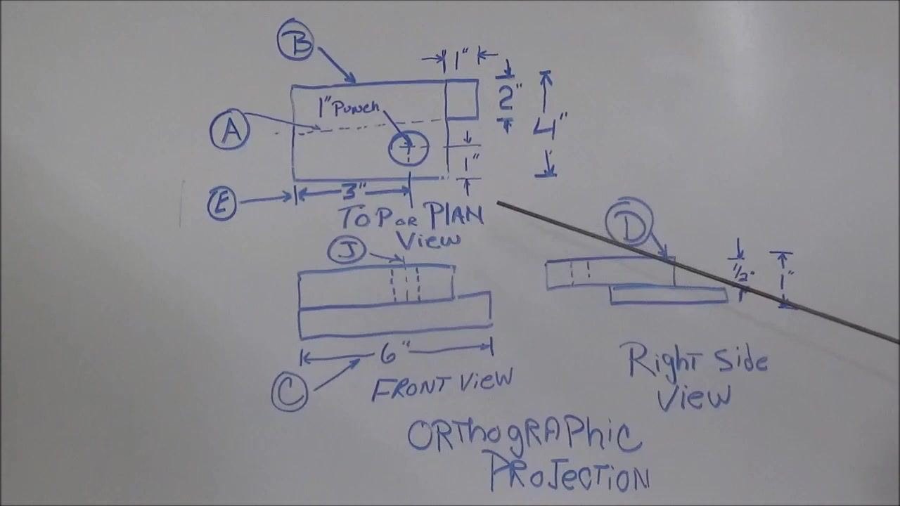
Once you can name each line type, practice evaluating the drawing critically. Look at the prompt written on the print, "What is wrong with the right side view?", and use your knowledge of the line types to check the view for potential errors or inconsistencies.
Identify the center line and read the specifications
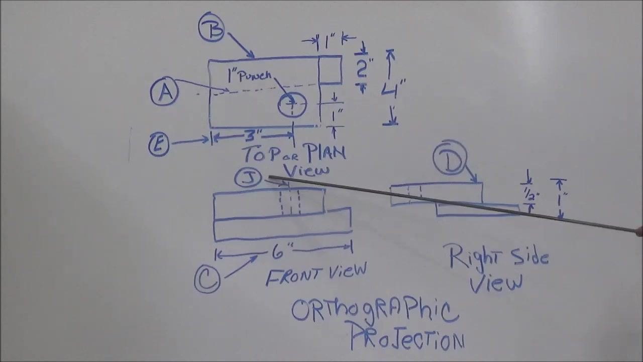
Locate the center line labeled "J" running through the middle of the object in the Front View. This center line marks the exact location where the hole is to be punched.
Then review the specifications on the print:
- The note "1'' Punch" near the hole in the Top/Plan View specifies that the hole must be punched (not drilled) to a diameter of 1 inch.
- The overall object size is 4 inches by 6 inches, as shown in the Top/Plan and Front Views.
- The smaller section of the material is 2 inches wide, as shown in the Top/Plan View.
- The material thickness is 1/2 inch, and the overall height is 1 inch, as shown in the Right Side View.
In the Top/Plan View, confirm the following measurements: 1 inch from the top edge to the top of the smaller section, 2 inches for the height of the smaller section, 4 inches for the total height, 3 inches from the left edge to the center of the hole, and 1 inch from the right edge to the right side of the smaller section. In the Front View, confirm the 6-inch length of the object.
Check the print for missing information
Before fabricating from a print, check it for completeness:
- Ask yourself whether you could build the object from the information provided.
- Look for missing details, such as a center line that is absent from one of the views, since missing center lines or other key details can lead to fabrication errors.
- Confirm that every labeled line and dimension matches its correct function and location on the drawing.
Review the complete orthographic projection drawing
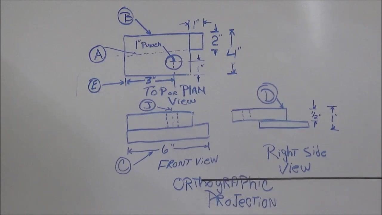
Review a full orthographic projection example that ties together everything covered in the previous steps:
- Three main views: Top or Plan View, Front View, and Right Side View
- Labeled lines (A, B, C, D, E, J) across the views
- Dimensions in the Top/Plan View: 1" Punch, 1" from the left edge, 1" from the right edge, 2" from the top, 4" total height, 3" width
- Dimension in the Front View: 6" width
- Dimensions in the Right Side View: 1/2" and 1" heights
- A mix of line types: fine lines, thick lines, heavy lines, extension lines, and dimension lines
Verification and summary
You have completed the procedure for how to read a welding blueprint when you can:
- Identify the Object Line, Hidden Line, Center Line, Dimension Line, and Extension Line on any print
- Recognize the Top/Plan View, Front View, and Right Side View (and Left Side or Bottom View when present)
- Read punch and dimension specifications, such as hole size and material thickness
- Check a print for missing information, such as an absent center line, before fabrication begins
What's next
Continue building your skills by practicing on additional sample prints, applying the same process: identify the line types, confirm the views, read the dimensions and specifications, and check the drawing for completeness. This reading and drawing skill supports clear communication of technical ideas to supervisors, engineers, and team members in welding and metal fabrication.
Generation details: cost, quality tiers
Docsie billed 3,500 credits ($2.45) to analyze this 7-minute video at standard quality. The rewrite, template fill and Word/PDF exports were included. The same video at each quality tier:
| Quality | Frames sampled | Credits | Approx. cost |
|---|---|---|---|
| Draft | every 16-30 s | 1,750 | $1.22 |
| Standard (this guide) | every 8-15 s | 3,500 | $2.45 |
| Detailed | every 4-7 s | 7,000 | $4.90 |
| Ultra | every 1-3 s | 14,000 | $9.80 |
Credits priced at $0.70 per 1,000; plans include a monthly allowance. Enterprise customers on on-premise or bring-your-own-model deployments run this on their own inference and pay no per-video credits.
Generated by Docsie Video-to-Docs on 2026-09-08 from a 6-minute video. Screenshots are frames from the source video and belong to their creator, hanging with heavy, whose original is embedded above. If you own this video and want the guide removed or credited differently, contact us and we will act within one business day.