
How to Program a PLC
This SOP explains how to program a PLC for a liquid mixing and transfer system using an S7-300 PLC and Step 7 software. You will review the system layout and control logic, then configure the PLC hardware, simulate the configuration, download it to a virtual CPU, and open the main program block where the control logic will be written.
Video: PLC Programming Tutorial for Beginners_ Part 1 by RealPars (2014). All credit for the demonstration goes to the creator; watch the original on YouTube. The written guide below was generated from this video by Docsie. Creator? Request a change or removal.
This SOP explains how to program a PLC for a liquid mixing and transfer system using an S7-300 PLC and Step 7 software. You will review the system layout and control logic, then configure the PLC hardware, simulate the configuration, download it to a virtual CPU, and open the main program block where the control logic will be written.
Purpose
This procedure guides you through the preparation stages required before writing PLC logic: understanding the mixing tank process, creating a Step 7 project, configuring the S7-300 rack and modules, verifying the configuration through simulation, and opening the main program block (OB1) for programming.
Scope
This procedure covers: - Reviewing the mixing tank system layout and process sequence. - Creating a new project in SIMATIC Manager. - Configuring the PLC rack, power supply, CPU, and digital input/output modules in HW Config. - Simulating and downloading the configuration using S7-PLCSIM. - Opening the OB1 main program block to prepare for programming.
This procedure does not cover writing the ladder logic instructions themselves; that is addressed in a follow-up lesson.
Prerequisites and required equipment
Before you begin, confirm you have the following: - A computer with SIMATIC Manager (Step 7 software) installed. - Access to the S7-PLCSIM simulator. - Knowledge of the target hardware: a SIMATIC S7-300 rack, a PS 307 2A power supply, a CPU 316, a SM 321 DI16xDC24V digital input module, and a SM 322 DO16xDC24V/0.5A digital output module. - Familiarity with the physical process: a tank with two pumps, two level switches, a mixer, and a discharge valve.
Understand the mixing tank system
1.1 Review the system layout
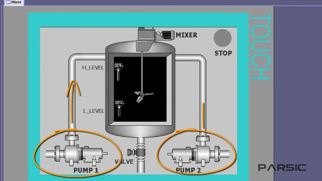
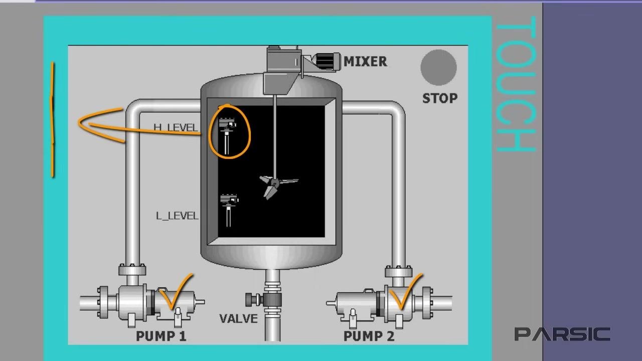
Before you program a PLC for this application, observe the main process diagram. It includes a central tank with two level switches labeled H_LEVEL (high) and L_LEVEL (low), two pumps labeled PUMP 1 and PUMP 2 connected to the tank via pipes, a mixer mounted on top of the tank labeled MIXER, a discharge valve at the bottom labeled VALVE, and a STOP button with a TOUCH label on the interface. The system is displayed on a graphical user interface that is part of the HMI (Human-Machine Interface).
1.2 Understand the function of each component
- Pumps (PUMP 1 and PUMP 2): Transfer two separate liquids into the tank, each through its own pipe.
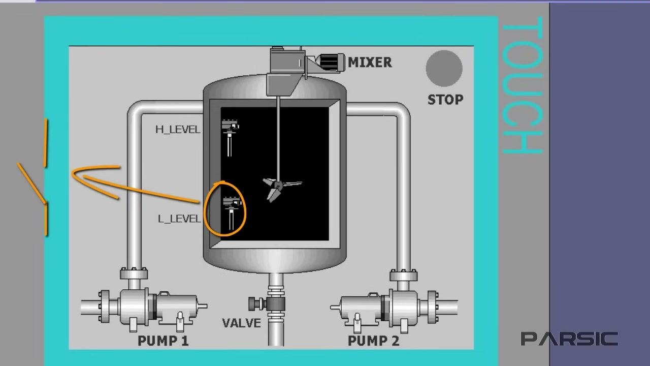
- Level switches: Two digital switches installed inside the tank. L_LEVEL (lower part) detects the minimum liquid level; H_LEVEL (upper part) detects when the tank is full. Each switch can only be true (closed) or false (open).
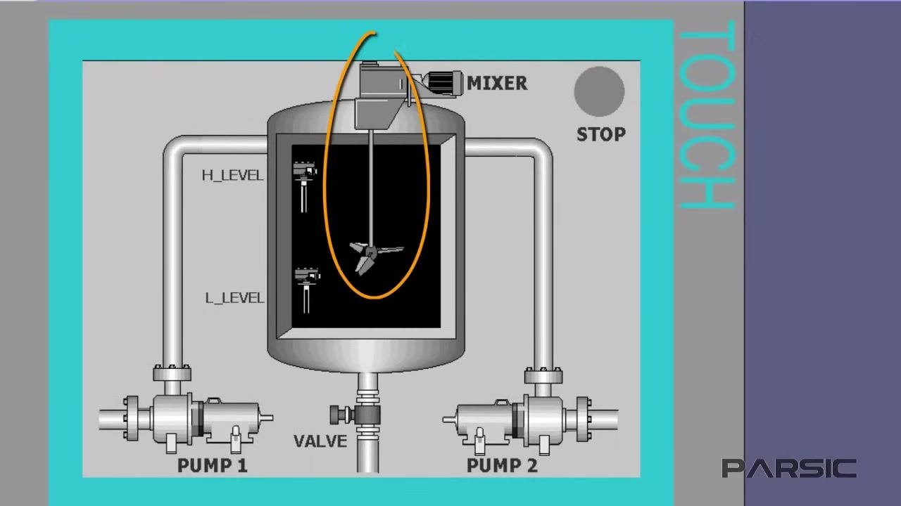
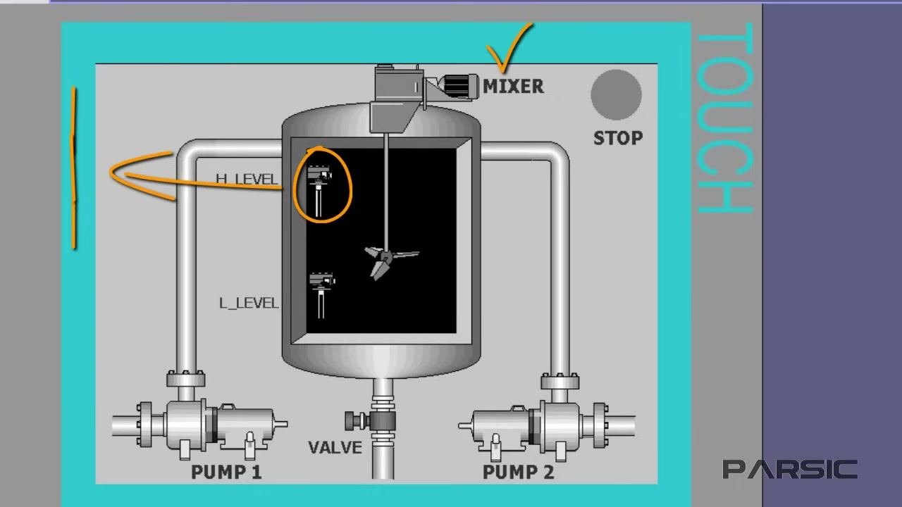
- Mixer: An electrically powered mixer installed inside the tank. It runs for a defined period after the tank is filled to blend the two liquids.
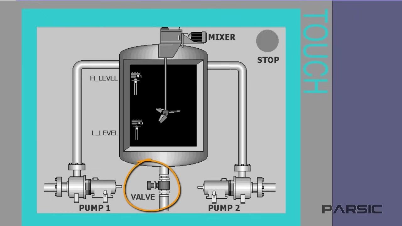
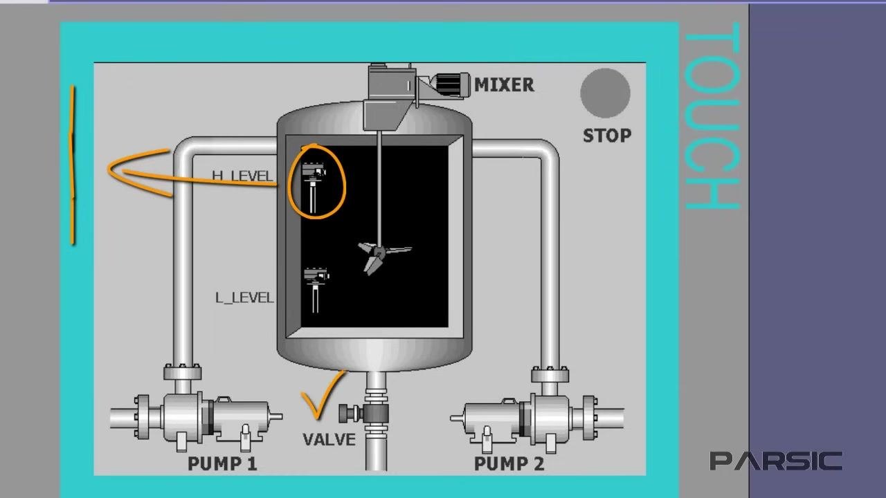
- Discharge valve: Located at the bottom of the tank, it controls draining of the mixed liquid.
1.3 Review the fill sequence
When the liquid level in the tank drops to the position of the lower level switch (L_LEVEL), the switch closes and sends a 24V DC signal to the PLC input. The PLC program must be written so that, upon receiving this signal, both pumps activate to begin filling the tank with the two liquids.
1.4 Review mixer operation
After the tank is filled and the upper level switch (H_LEVEL) is triggered, the mixer starts and runs for a defined period to mix the contents.
1.5 Review the discharge process
Once mixing is complete, the discharge valve at the bottom of the tank opens to drain the mixed liquid.
1.6 Review the overall control logic
The PLC receives input from the level switches. When the lower level switch activates, both pumps start filling the tank. When the upper level switch activates, the pumps stop and the mixer starts. After mixing, the discharge valve opens to empty the tank.
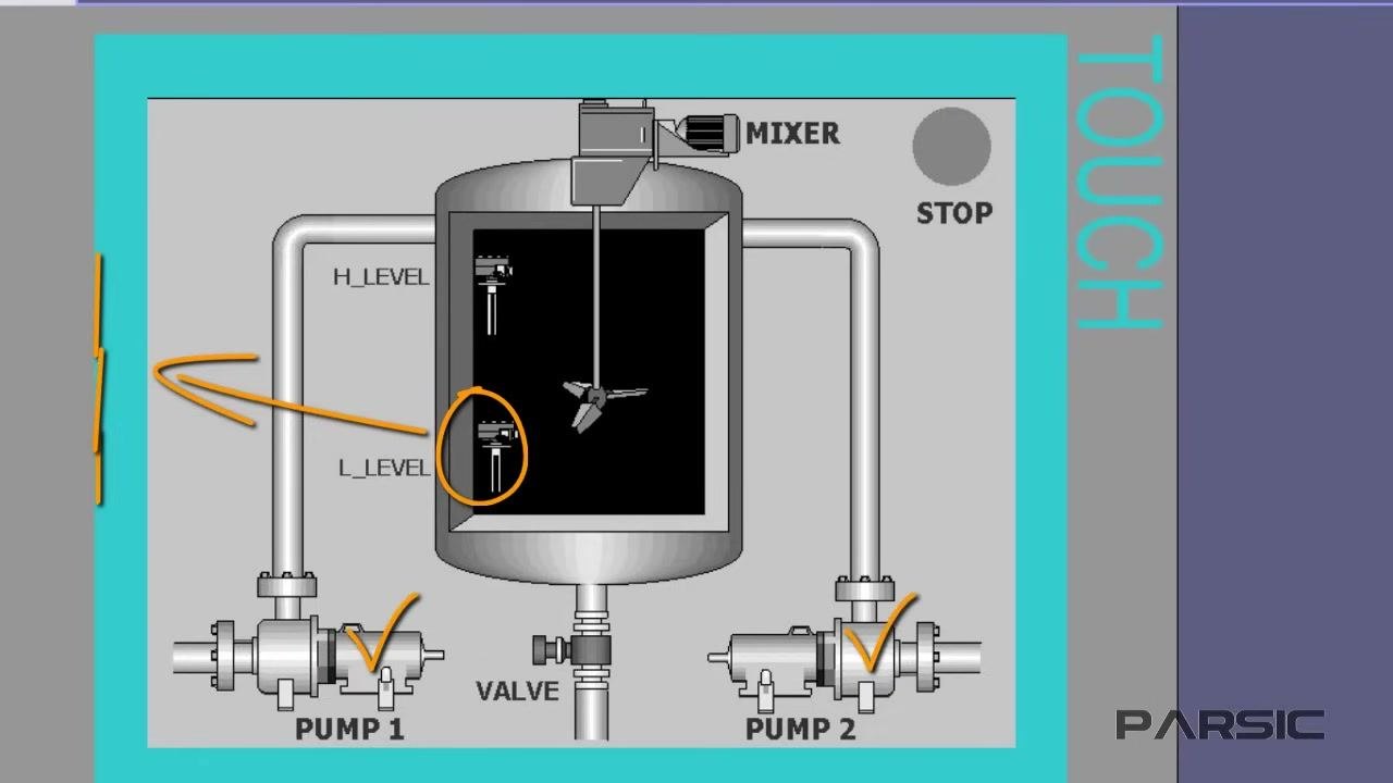
Review the complete PLC control sequence
The pumps (PUMP 1 and PUMP 2) continue filling the tank until the liquid reaches the maximum level at the H_LEVEL switch. When high level is reached, the H_LEVEL switch contacts close, sending a 24V DC signal to the PLC input to indicate the tank is full. The PLC must then shut down both pumps and start the mixer.
The mixer operates for exactly 7 seconds to ensure proper mixing. After 7 seconds, the mixer automatically shuts down and the discharge valve opens, allowing the mixed liquid to be transferred out of the tank for further processing. As the tank empties and the liquid drops to the minimum at the L_LEVEL switch, the contacts close again, sending a signal to the PLC to restart the cycle. This sequence repeats automatically as long as the system is running.

Launch SIMATIC Manager and create a project
3.1 Launch SIMATIC Manager
On your computer desktop, locate the SIMATIC Manager icon. This program manages sub-programs of Step 7 and is used to create and organize PLC projects. Double-click the SIMATIC Manager icon to launch the application.
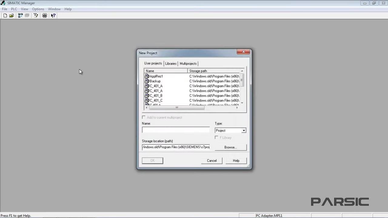
3.2 Create a new project
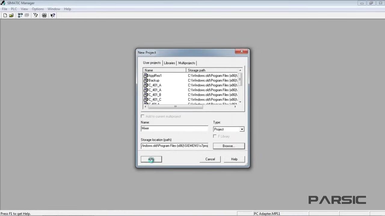
Once SIMATIC Manager opens, click the New icon on the toolbar to open the New Project window. In the dialog, enter a name for your project in the Name field, choose the storage location path for your project files, and confirm that Type is set to Project. Click OK to create the new project.
Configure the new project and insert the PLC station
4.1 Enter the project name
In the New Project window, enter the project name in the Name field. Enter Mixer. Confirm that the Type field is set to Project, and note the default storage location shown in the Storage location (path) field.
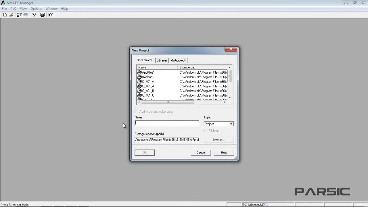
4.2 Set the storage location (optional)
If you want to change the storage location for your project files, click the Browse button next to the Storage location (path) field, navigate to your desired folder, and select it. Confirm the new path is displayed, then click OK to create the project.
4.3 Insert the SIMATIC 300 station
In the SIMATIC Manager main window, click the name of your newly created project (Mixer) to highlight it. From the top menu, go to Insert > Station and select 2 SIMATIC 300 Station. This step is required because the machine is controlled by an S7-300 PLC.
4.4 Verify the station was added
Confirm that a subgroup named SIMATIC 300(1) appears under your project in the left pane.
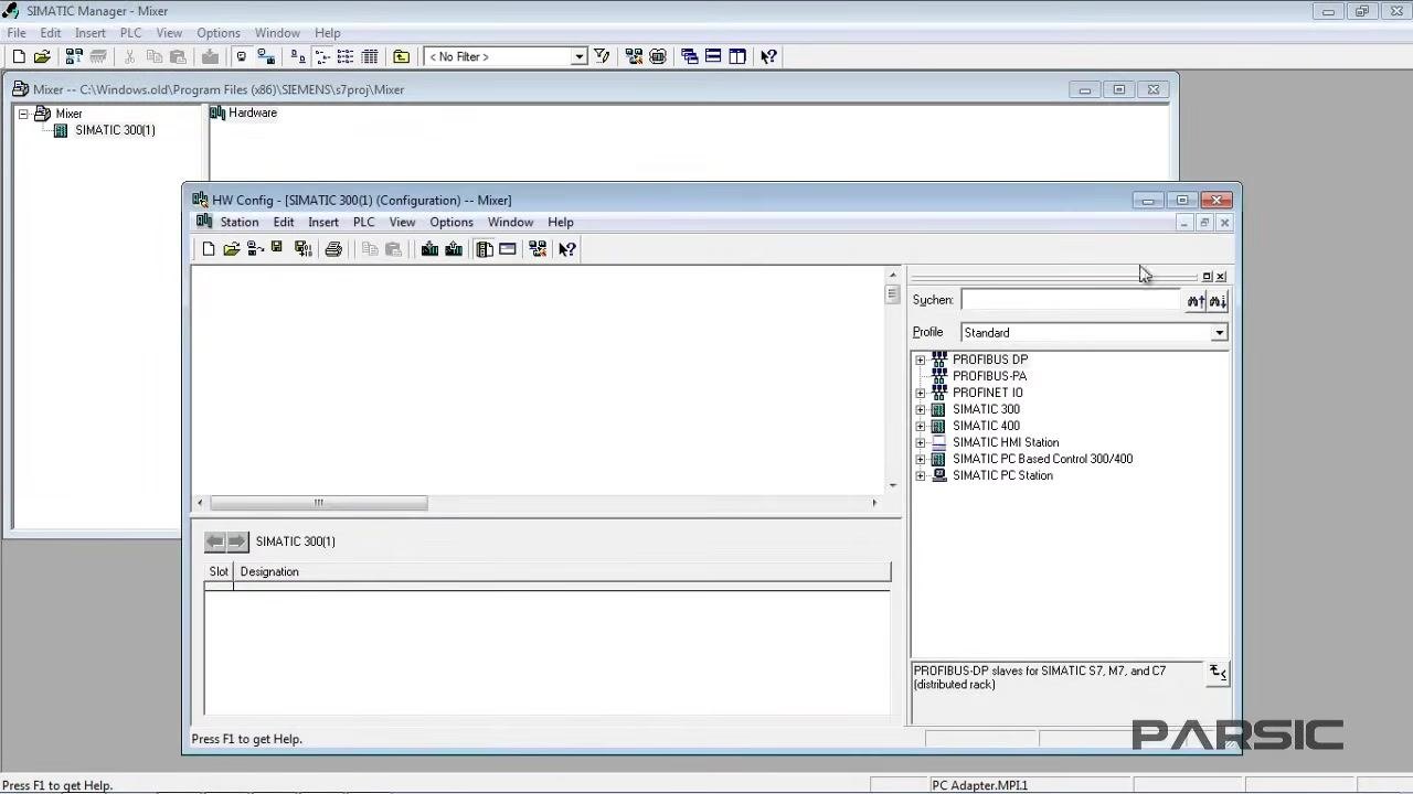
4.5 Open the hardware configuration
Click the Hardware icon under the SIMATIC 300(1) subgroup. This opens the hardware configuration environment, where you set up the modules required for your PLC.
4.6 Locate the SIMATIC 300 module catalog
In the hardware configuration window (HW Config), locate the SIMATIC 300 folder in the right pane. This pane lists all available module categories for the S7-300 series.
4.7 Insert the rack
Expand the SIMATIC 300 folder in the right pane, find and select RACK-300, then double-click it to add it to the configuration area on the left. The rack is the physical frame for mounting the PLC modules.
Configure the PLC rack
5.1 Install the power supply module in slot 1
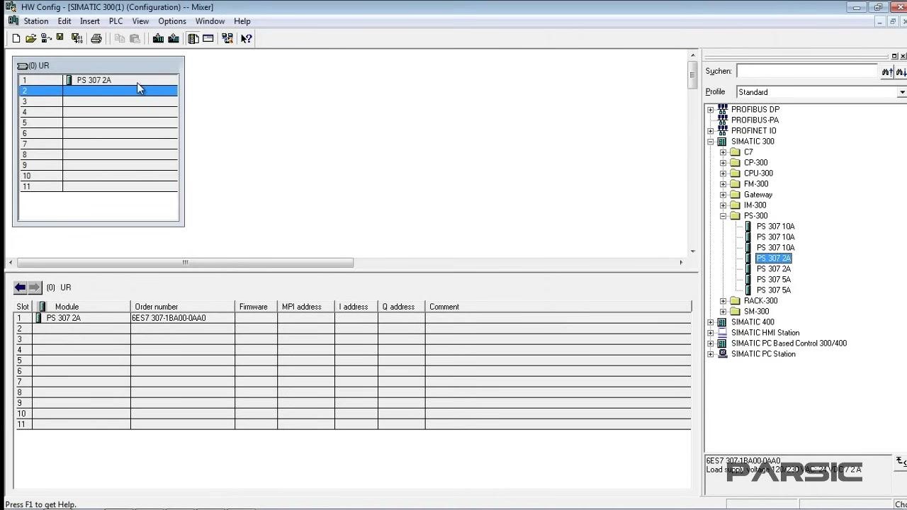
In the HW Config - [SIMATIC 300(1) (Configuration)] window, the main workspace displays an empty rack with 11 slots labeled 1 to 11. Locate the PS-300 folder in the hardware catalog on the right, select PS 307 2A, and drag it into slot 1. Confirm that slot 1 displays PS 307 2A in both the rack diagram and the module table, and that the order number (6ES7 307-1BA00-0AA0) appears in the lower table.
5.2 Verify the module order number
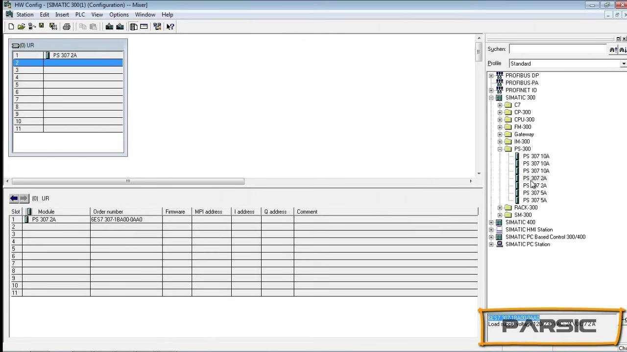
Click on the installed power supply in slot 1. Observe that its order number is displayed and highlighted in the bottom right of the window. Always confirm the order number matches the physical module you intend to use in your enclosure.
5.3 Install the CPU module in slot 2
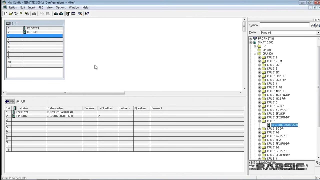
In the hardware catalog, expand the CPU-300 folder to reveal available CPU modules. Select CPU 316 (order number 6ES7 316-1AG00-0AB0) and drag it into slot 2. Confirm that slot 2 displays CPU 316 in both the rack diagram and the module table, along with the order number and MPI address (2).
5.4 Plan the digital input and output modules
After installing the power supply and CPU, plan to add both a digital input and a digital output module to the rack. These will occupy the next available slots (typically slots 3 and 4). Ensure you select the correct digital input and output modules from the hardware catalog before proceeding.
Add digital input and output modules
6.1 Attempt to insert the digital input module
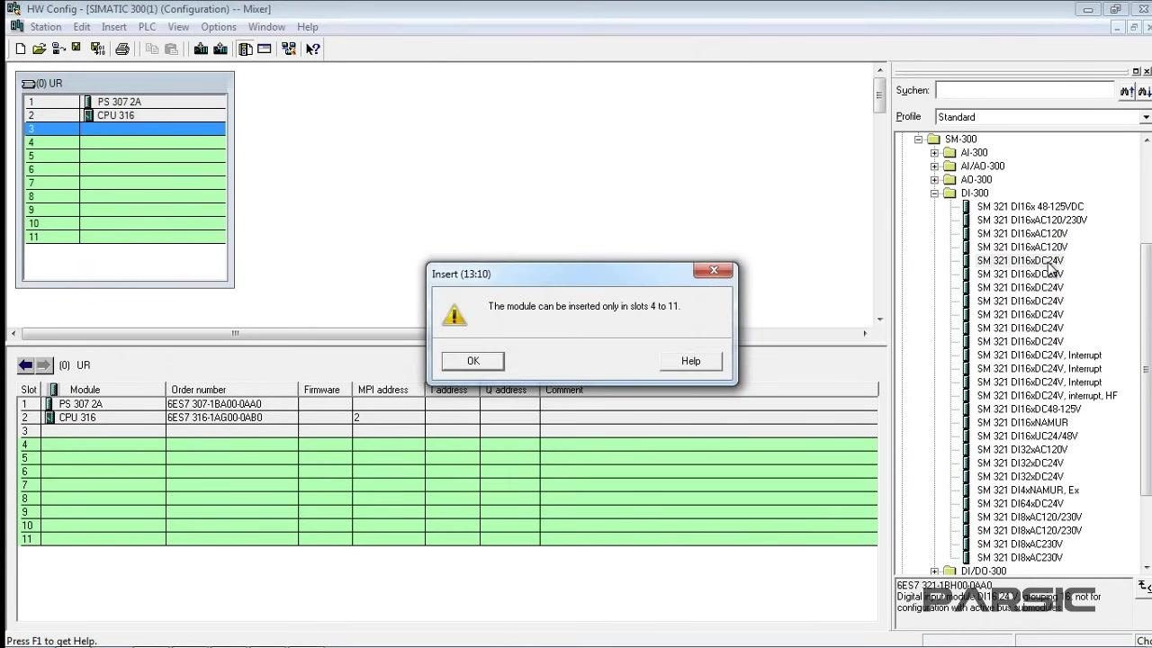
In the hardware catalog, expand the SM-300 folder, then the DI-300 folder, to locate SM 321 DI16xDC24V (16 digital inputs, 24V). Double-click the module and attempt to place it in slot 3. A warning message appears: "The module can be inserted only in slots 4 to 11."
Safety note: Do not force a module into a restricted slot. Follow the tool's slot guidance to avoid configuration errors.
6.2 Acknowledge the slot restriction
Click OK on the warning dialog to close it. Slot 3 must remain empty for this configuration.
6.3 Insert the digital input and output modules in the correct slots
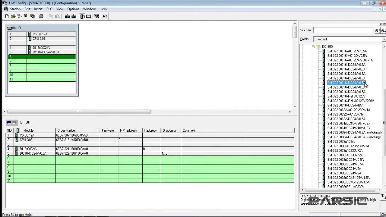
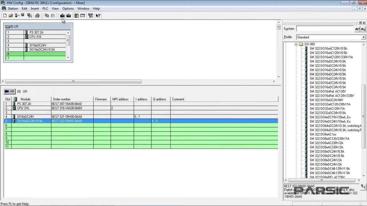
Select slot 4 and double-click SM 321 DI16xDC24V again to insert it there. Confirm that slot 4 displays DI16xDC24V, with order number 6ES7 321-1BH00-0AA0 and an I address range of 0...1 (bytes 0 and 1).
Next, expand the DO-300 folder, locate SM 322 DO16xDC24V/0.5A (16 digital outputs, 24V, 0.5A), and insert it into slot 5. Confirm that slot 5 displays DO16xDC24V/0.5A, with order number 6ES7 322-1BH10-0AA0 and a Q address range of 4...5 (bytes 4 and 5).
6.4 Verify address ranges
For the digital input module in slot 4, verify the I address range is 0...1, corresponding to input addresses I0.0 to I1.7 (16 inputs). For the digital output module in slot 5, verify the Q address range is 4...5, corresponding to output addresses Q4.0 to Q5.7 (16 outputs).
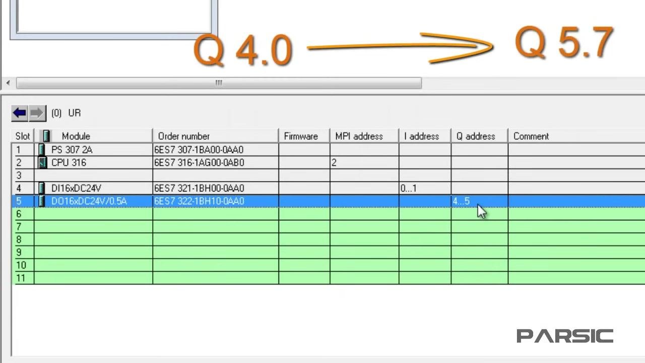
Always insert digital input modules in slots 4 through 11, as required by the configuration tool. The I and Q address ranges are assigned automatically and correspond to the number of channels on each module. Double-check that order numbers and address ranges match your intended configuration.
Simulate and download the configuration
7.1 Confirm the configuration is complete
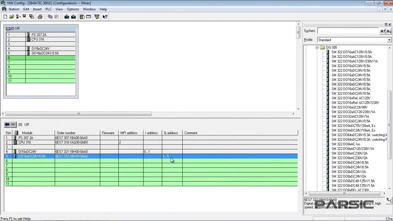
Before simulating, confirm that the digital input (DI16xDC24V) and digital output (DO16xDC24V/0.5A) modules are correctly inserted in slots 4 and 5, with the correct order numbers and address ranges.
7.2 Open the PLC simulator
Launch S7-PLCSIM from within SIMATIC Manager. A small window labeled S7-PLCSIM1 appears, showing CPU status indicators (SF, DP, DC, RUN, STOP, RUN-P, MRES). The main SIMATIC Manager window remains open in the background.
7.3 Select the input variables
In the S7-PLCSIM1 window, locate the input byte (IB) panel. By default, IB 0 is selected, displaying bits 0 to 7. You can toggle individual input bits to simulate digital input signals.
7.4 Configure the output variable
Open the output byte (QB) panel in S7-PLCSIM1. Change the output byte address from QB 0 to QB 4 to match the address range of your digital output module (Q4...5). This ensures you monitor and control the correct output channels.
7.5 Save and compile the hardware configuration
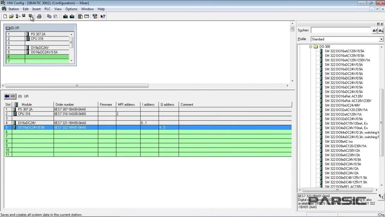
Return to the HW Config window and click the Save and Compile icon (floppy disk with gear) in the toolbar to save your configuration and generate system data. Wait for the process to complete before proceeding.
7.6 Download the configuration
Click the Download icon (downward arrow) in the HW Config toolbar. This initiates the download process to the target CPU (simulator).
7.7 Select the target CPU module
In the Select Target Module dialog, choose CPU 316 (Rack 0, Slot 2) as the download target. Click OK to confirm your selection.
7.8 Confirm the node address
In the Select Node Address dialog, verify Rack: 0, Slot: 2, MPI address: 2, and Module type: CPU841-0. Ensure the correct node is selected in the Accessible Nodes list, then click OK to proceed with the download.
7.9 Verify the configuration in the project tree
After downloading, return to SIMATIC Manager. In the project tree, confirm that a subgroup named CPU 316 now appears under SIMATIC 300(1). This indicates the configuration has been successfully assigned to the CPU.
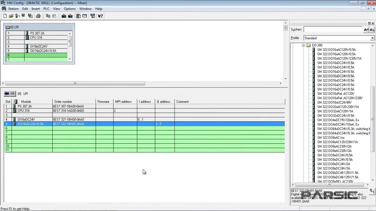
Always match the input (IB) and output (QB) addresses in the simulator to the address ranges assigned in HW Config. Saving and compiling before downloading ensures all changes are included in the system data. The download process requires selecting both the target CPU and the correct MPI node address.
Open the main program block (OB1)
8.1 Navigate to the OB1 block
In SIMATIC Manager, expand the project tree on the left. Under your project (Mixer), expand SIMATIC 300(1), then CPU 316, then the S7 Program(6) folder. Click on the Blocks folder to display available program blocks, including OB1.
8.2 Open the OB1 block properties
Double-click OB1 in the block list. The first time you open it, a Properties - Organization Block window appears, showing Name: OB1, Symbolic Name and Symbol Comment (blank by default), Created in Language: LAD (Ladder Logic), the project path, and the date created, last modified, and comment fields. Click OK to open OB1 for editing.
8.3 View the OB1 program editor
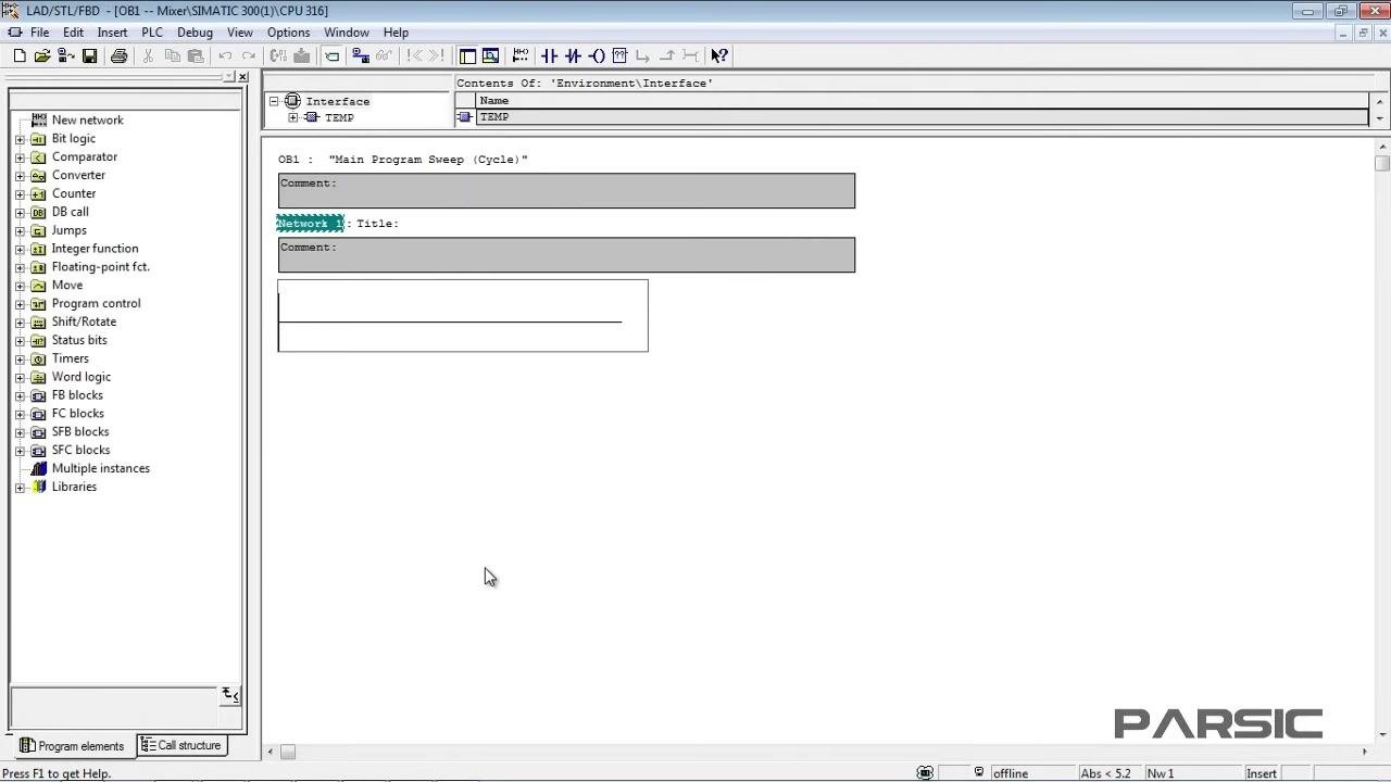
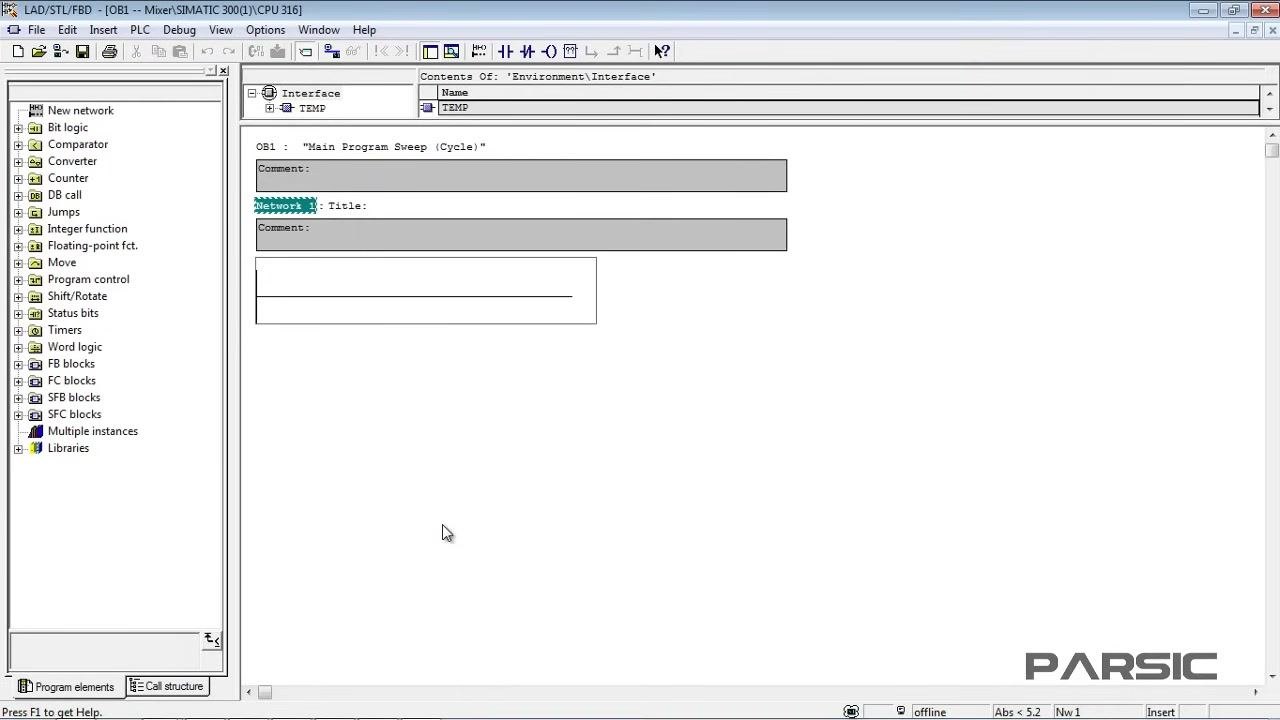
After confirming the properties, OB1 opens in the LAD/STL/FBD editor. The editor displays the OB1 title "Main Program Sweep (Cycle)," sections for comments and network titles, a toolbox on the left with programming elements such as Bit logic, Comparator, Counter, DB call, Jumps, Integer function, Timers, Word logic, FB/FC/SFB/SFC blocks, and Libraries, and an interface section at the top showing TEMP variables. You are now ready to begin programming in OB1.
Always ensure you are working in the correct project and CPU before editing OB1. This block is the main cyclic program block in Siemens PLCs, where your primary logic will be placed. Use the programming toolbox to insert logic elements as needed in your program networks.
Verification
Before moving on to writing program logic, confirm the following: - The Mixer project exists in SIMATIC Manager with a SIMATIC 300(1) station. - The rack contains PS 307 2A in slot 1, CPU 316 in slot 2, DI16xDC24V in slot 4, and DO16xDC24V/0.5A in slot 5, with correct order numbers and address ranges. - The hardware configuration has been saved, compiled, and downloaded to the CPU 316 target, and the CPU 316 subgroup appears in the project tree. - The OB1 block opens correctly in the LAD/STL/FBD editor, ready for programming.
What's next
With the project created, the hardware configured, the configuration simulated and downloaded, and OB1 open in the editor, you are ready to write the control logic using simple and practical instructions to control the mixing tank machine, as covered in the next lesson.
Generation details: cost, quality tiers
Docsie billed 5,500 credits ($3.85) to analyze this 11-minute video at standard quality. The rewrite, template fill and Word/PDF exports were included. The same video at each quality tier:
| Quality | Frames sampled | Credits | Approx. cost |
|---|---|---|---|
| Draft | every 16-30 s | 2,750 | $1.92 |
| Standard (this guide) | every 8-15 s | 5,500 | $3.85 |
| Detailed | every 4-7 s | 11,000 | $7.70 |
| Ultra | every 1-3 s | 22,000 | $15.40 |
Credits priced at $0.70 per 1,000; plans include a monthly allowance. Enterprise customers on on-premise or bring-your-own-model deployments run this on their own inference and pay no per-video credits.
Generated by Docsie Video-to-Docs on 2026-09-09 from a 10-minute video. Screenshots are frames from the source video and belong to their creator, RealPars, whose original is embedded above. If you own this video and want the guide removed or credited differently, contact us and we will act within one business day.