
How to Use a Multimeter
This document provides step-by-step instructions for using a digital multimeter (CEN-TECH P37772 or similar) to measure DC voltage, AC voltage, resistance, continuity, and current. Follow each procedure in sequence to obtain safe and accurate electrical readings.
Video: How to Use a Multimeter for Beginners - How to Measure Voltage, Resistance, Continuity and Amps by Ratchets And Wrenches (2015). All credit for the demonstration goes to the creator; watch the original on YouTube. The written guide below was generated from this video by Docsie. Creator? Request a change or removal.
This document provides step-by-step instructions for using a digital multimeter (CEN-TECH P37772 or similar) to measure DC voltage, AC voltage, resistance, continuity, and current. Follow each procedure in sequence to obtain safe and accurate electrical readings.
Purpose
This SOP guides you through the correct setup and use of a digital multimeter for common electrical diagnostic tasks, including measuring DC voltage from batteries, AC voltage from wall outlets, resistance in components and wires, continuity in circuits, and current draw in electrical loads.
Scope
This procedure applies to anyone using a digital multimeter for basic electrical testing, including automotive diagnostics (batteries, wire harnesses, spark plug wires) and household electrical checks (wall outlets). It covers voltage, resistance, continuity, and current measurement, along with safety precautions for each.
Required equipment
- Digital multimeter (e.g., CEN-TECH P37772) with red and black test leads
- Components or circuits to be tested (e.g., batteries, wall outlets, wire harnesses, spark plug wires, light bulbs)
- Alligator clips (optional, for secure connections)
- A flat, stable work surface
- A screwdriver or similar tool (optional, for precise dial adjustment)
Step-by-step procedure
Part 1: Measuring DC voltage
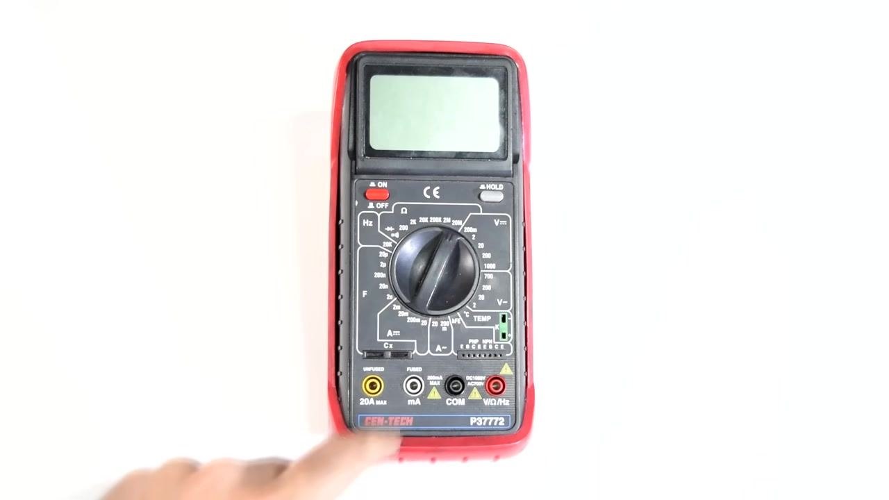
- Identify the multimeter and its controls
- Place the multimeter on a flat surface.
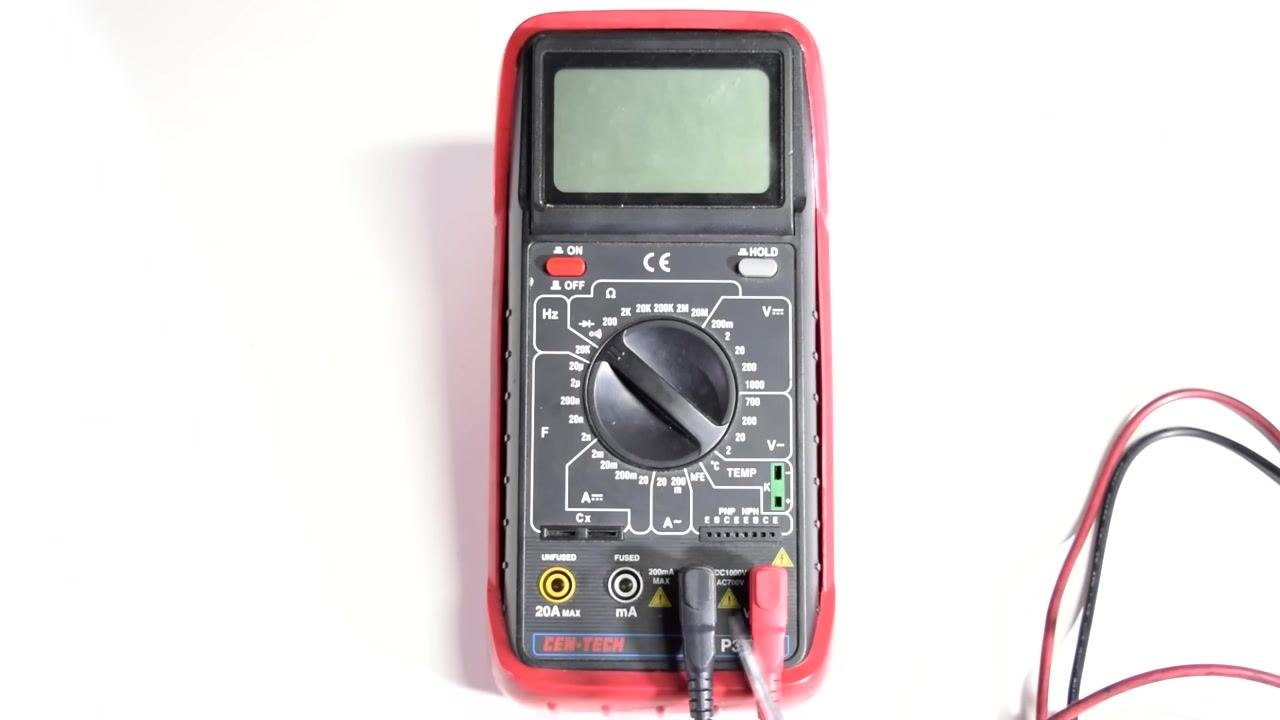
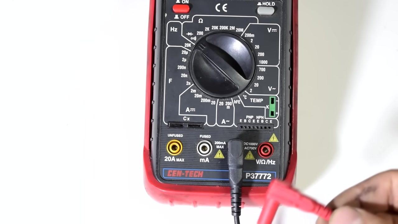
- Familiarize yourself with the main dial, display screen, and input ports labeled 20A MAX, mA, COM, and V/Ω/Hz.
- Note the location of the ON/OFF switch and the HOLD button.
-
Understand what you can measure
- The multimeter can measure DC voltage, AC voltage, resistance, continuity, and current (amps).
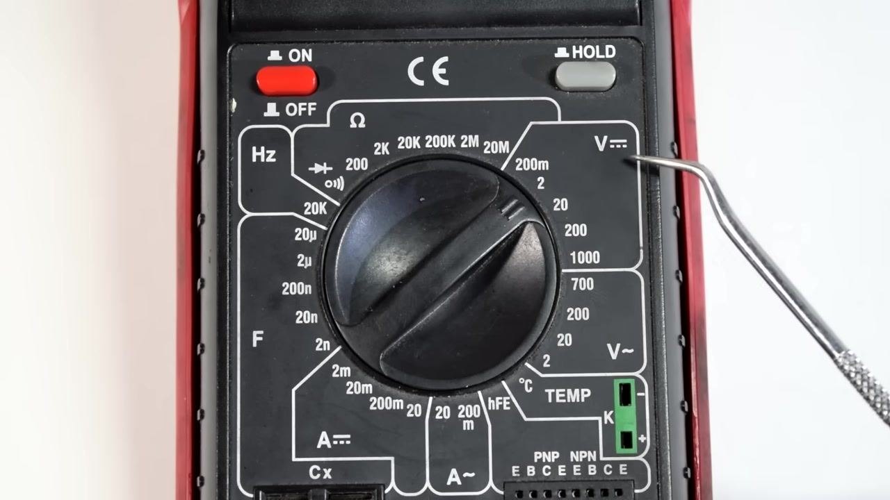
- The dial includes dedicated sections for each measurement type, marked with symbols for voltage (V), resistance (Ω), and current (A).
-
Identify DC voltage sources
- DC voltage is supplied by batteries and battery-powered devices, such as car batteries, cordless drills, and cameras.
- Any device that uses batteries operates on DC voltage.
-
Set the multimeter to measure DC voltage
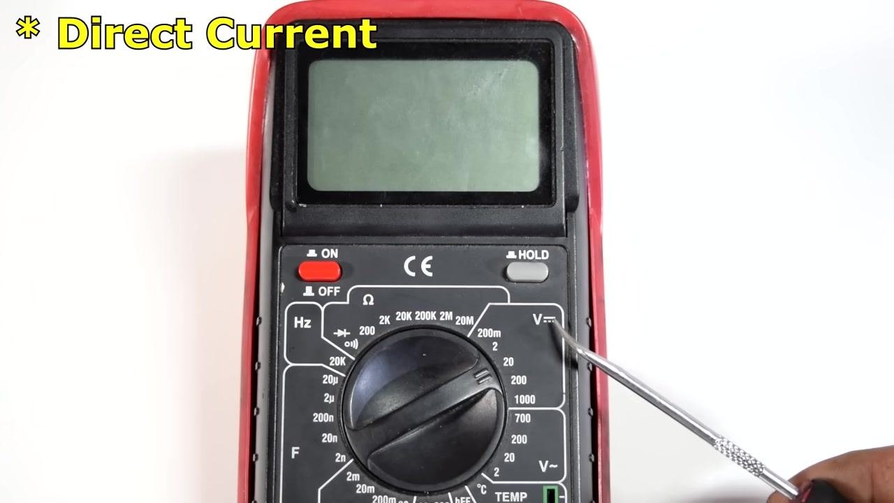
- DC stands for Direct Current.
- Turn the dial to the DC voltage section, indicated by a "V" with a straight and dotted line (V⎓).
- Confirm the multimeter is powered on.
-
Insert the test leads correctly
- Insert the black (common/ground) test lead into the port labeled COM.
- Insert the red (positive) test lead into the port labeled V/Ω/Hz for voltage measurements.
-
Set the dial to the appropriate voltage range
- Determine the maximum voltage you expect to measure.
- Set the dial to the next highest value above your expected voltage. For a 1.5V AA battery, set the dial to 2V in the DC voltage section.
-
Measure the voltage
- Place the red (positive) test lead on the positive terminal of the battery or circuit.
- Place the black (ground) test lead on the negative terminal.
- Read the displayed voltage. A fully charged AA battery should read approximately 1.5V to 1.6V.
- Handle uncertain voltage levels
- If you are unsure of the expected voltage, start with a higher range (e.g., 200V) and then lower the range for a more precise reading.
Note: If the test leads are connected in reverse during a DC voltage measurement, the multimeter will display a negative sign next to the reading. This does not damage the multimeter and can help you identify the positive and negative sides of the circuit.
Part 2: Measuring AC voltage
-
Prepare for AC voltage measurement
- AC (Alternating Current) voltage is used by any device that plugs into a wall socket.
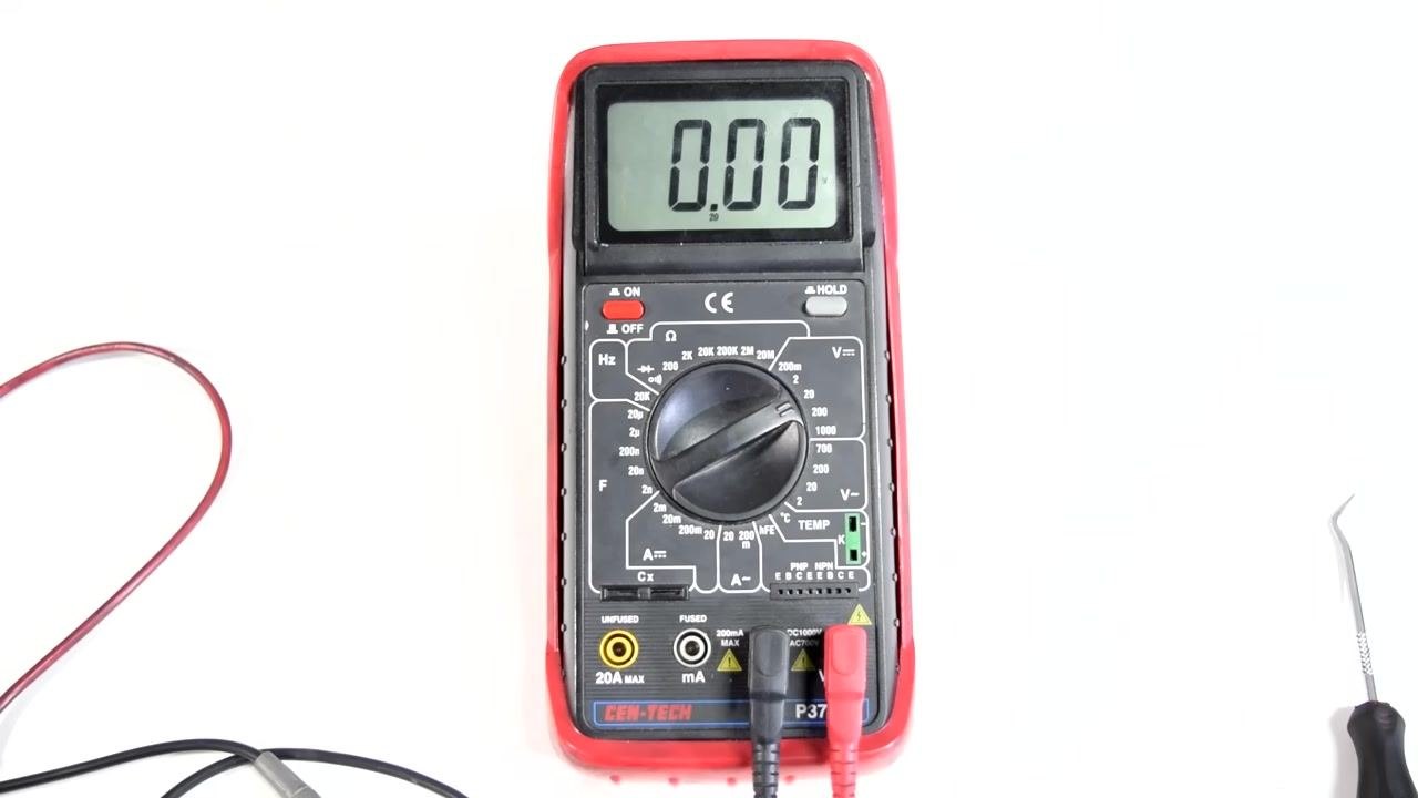
- Keep the black lead in the COM port and the red lead in the V/Ω/Hz port, the same ports used for DC voltage measurement.
-
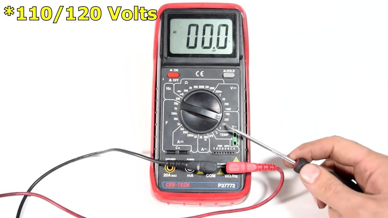
Switch the dial to AC voltage
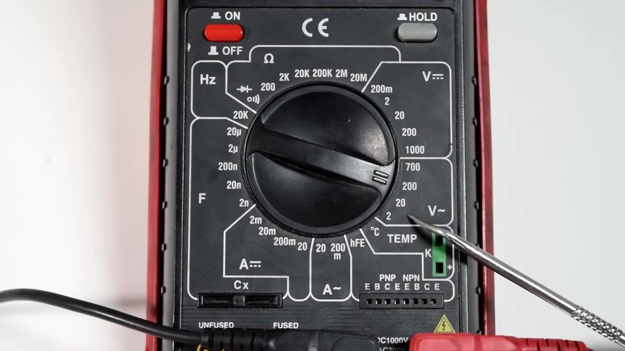
- Turn the dial from the DC voltage section to the AC voltage section, indicated by a "V" with a wave symbol (V~).
- Confirm the multimeter is powered on.
-
Set the appropriate voltage range
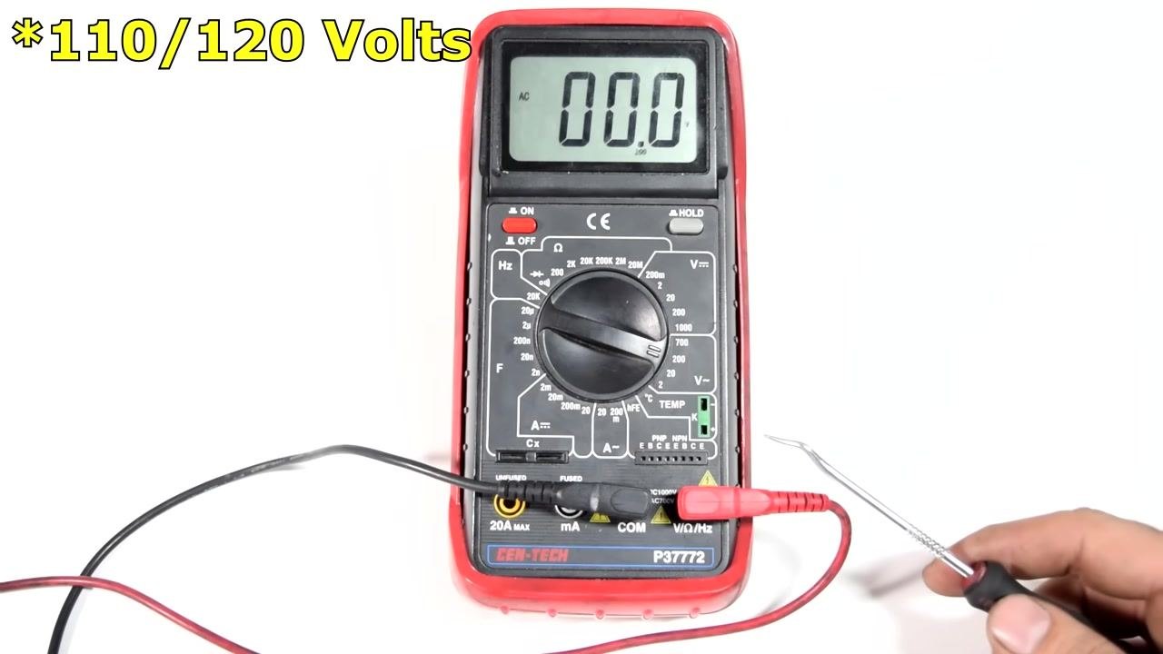
- Standard wall outlets in the United States supply approximately 110 to 120 volts AC.
- Set the dial to the next highest range above the expected voltage; in this case, 200V.
-
Follow safety precautions before measuring AC voltage
- Confirm that the multimeter and test leads are in good condition and rated for the voltage being measured.
- Keep your fingers away from the metal tips of the test leads.
- Ensure the test leads do not touch each other or come close together near the socket.
-
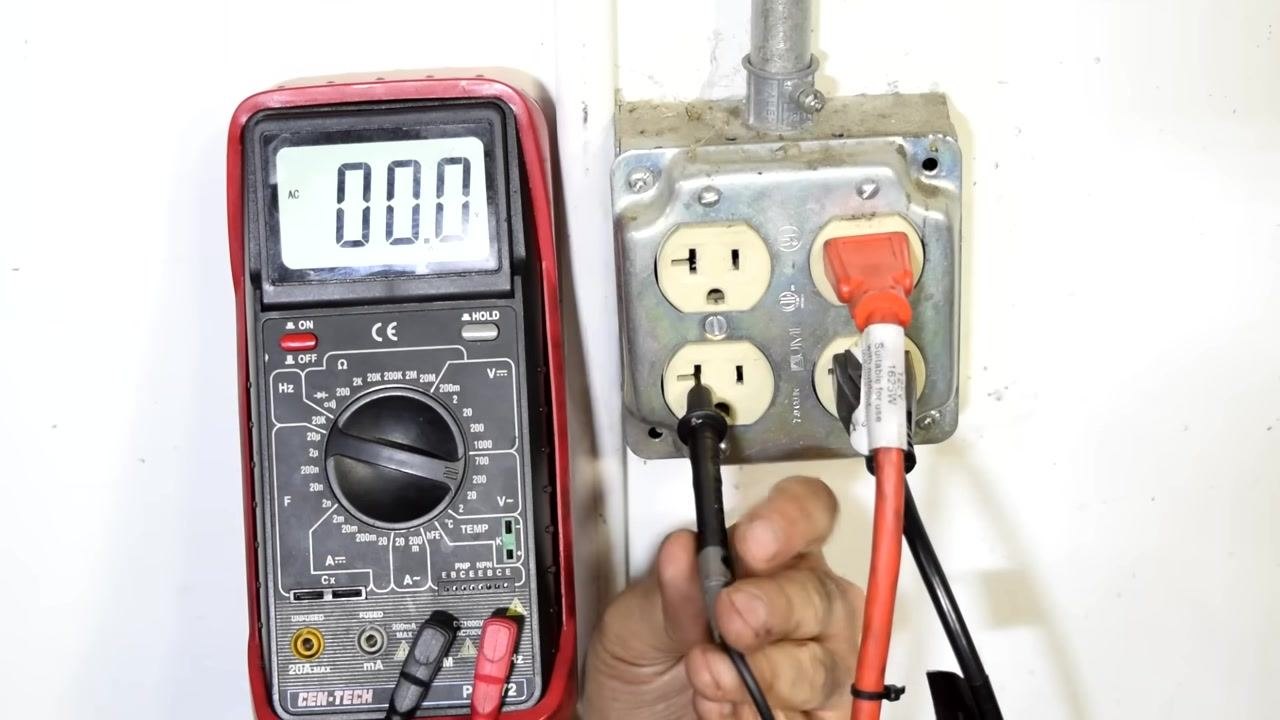
Measure AC voltage at a wall socket
- Insert the black (ground/COM) test lead into the larger slot of the wall socket (neutral).
- Insert the red (positive) test lead into the smaller slot (hot/live).
- Observe the reading on the multimeter display.
-
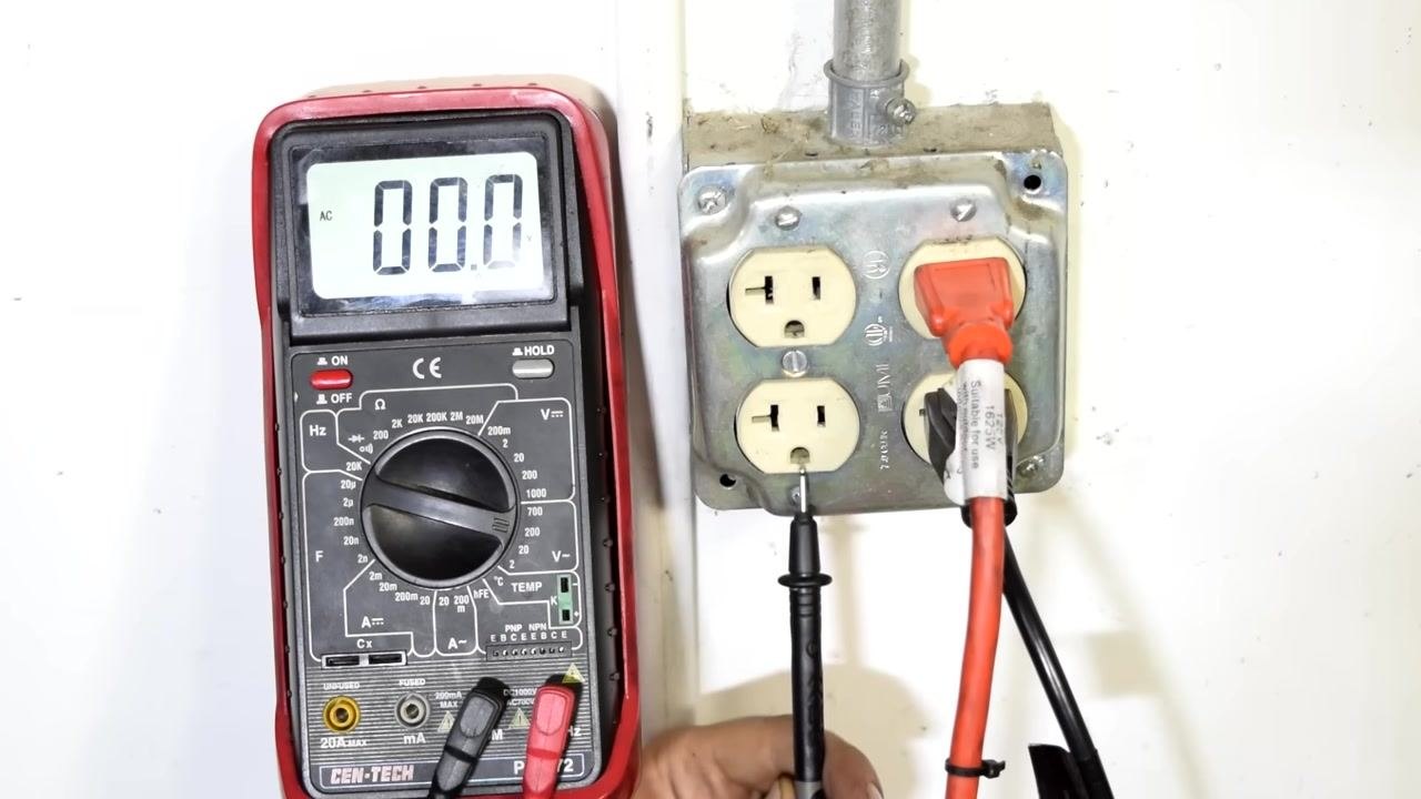
Check the case ground
- Insert one test lead into the ground slot (the round or D-shaped hole) of the outlet.
- Insert the other test lead into either the neutral or hot slot to verify a voltage reading, confirming the ground connection.
Part 3: Measuring resistance
- Understand resistance
- Resistance is the amount of opposition a material offers to the flow of electric current.
- Materials such as wood have high resistance, while metals such as wire have very low resistance.
- Different components in an electric circuit are designed with specific resistance values to ensure proper operation.
-
Prepare the multimeter for resistance measurement
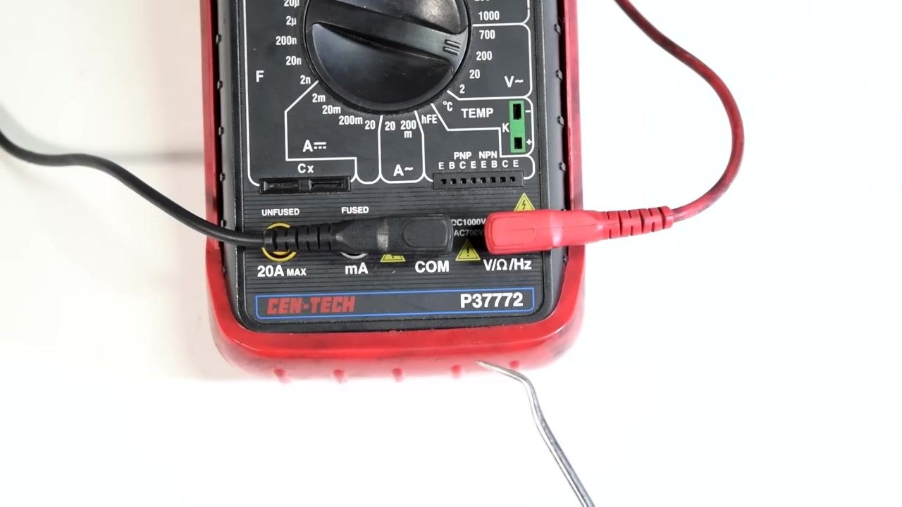
- Keep the black test lead in the COM port.
- Keep the red test lead in the V/Ω/Hz port.
- Turn the dial to the resistance (Ω) section, indicated by the horseshoe symbol.
-
Set the correct resistance range
- Determine the expected resistance value of the component being tested. For example, a spark plug wire may have an expected resistance of about 10,000 ohms (10kΩ).
- Set the dial to the next highest range above the expected value. For a 10kΩ measurement, set the dial to 20kΩ (20,000 ohms).
-
Connect the test leads to the component
- Attach the test leads to each end of the component whose resistance you want to measure, such as a spark plug wire.
- Ensure a secure connection for an accurate reading.
-
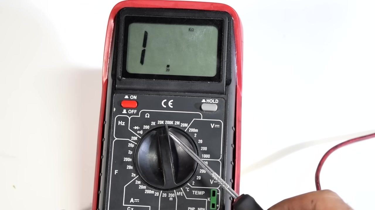
Read the resistance value
- Observe the reading on the multimeter display.
- If the display shows "1" or "OL", the resistance is out of range or the circuit is open; adjust the range if necessary.
- For the spark plug wire example, the display should show a value close to 9.87kΩ (9,870 ohms), within the expected specification.
-
Interpret the results
- Compare the measured resistance to the expected value for the component.
- If the value is significantly higher or lower than expected, the component may be faulty.
Part 4: Testing for continuity
-
Understand continuity testing
- Continuity testing checks whether an electric circuit allows current to flow from one point to another.
- The multimeter sends a small voltage through the circuit and verifies continuity, usually with a beep or alarm if the circuit is complete.
-
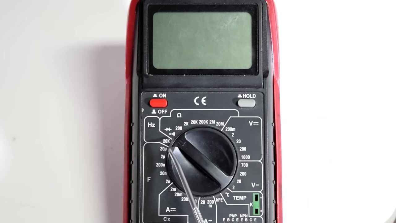
Set the multimeter to continuity mode
- Turn the dial to the continuity test icon, typically shown as a sound wave or diode symbol.
- Keep the test leads in the same ports used for resistance measurement.
Part 5: Testing resistance in wires and connectors
-
Confirm the multimeter is in resistance mode
- Verify that the rotary dial is set to the resistance (Ω) setting.
- Keep the test leads in the same position used for resistance testing.
- Confirm the multimeter display is on and ready for measurement.
-
Prepare to test wire continuity
- Identify the wires and connectors to be tested for continuity or resistance.
- Ensure the wires are accessible and the connectors are visible.
-
Attach test leads to the wire or connector
- Connect one test lead to one end of the wire or connector.
- Attach the other test lead to the corresponding pin or end of the connector.
- Use alligator clips if necessary for a secure connection.
- Observe the multimeter display for a reading.
-
Inspect for faults in the wire
- Look for signs of damage, such as cuts or burnt sections in the wire harness.
- Use the multimeter to check for continuity across the suspected damaged area.
- If the display shows no continuity, often indicated by "1" or "OL", the wire may be broken.
-
Apply the same method to other circuits
- This technique applies to larger circuits, such as automotive harnesses, or smaller circuits, such as a computer motherboard.
- Ensure all connections are secure and the multimeter is set correctly for each test.
Safety Note: Always disconnect power before testing resistance or continuity. Ensure the circuit is powered off and fully discharged before measuring, to prevent damage to the multimeter and ensure accurate readings.
Part 6: Measuring current (amps)
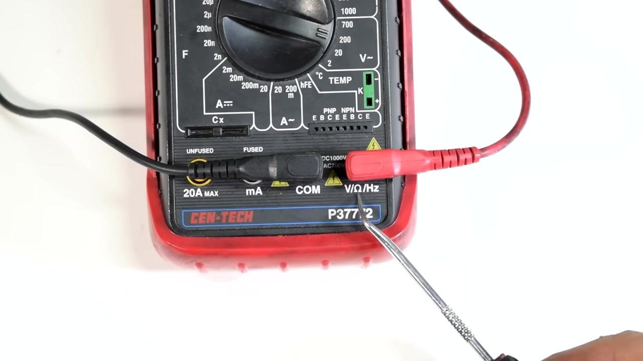
- Switch test lead position for current measurement
- To measure current, move the red test lead from the V/Ω/Hz port to the appropriate current port:
- Use the yellow 20A MAX port for high current, up to 20 amps, unfused.
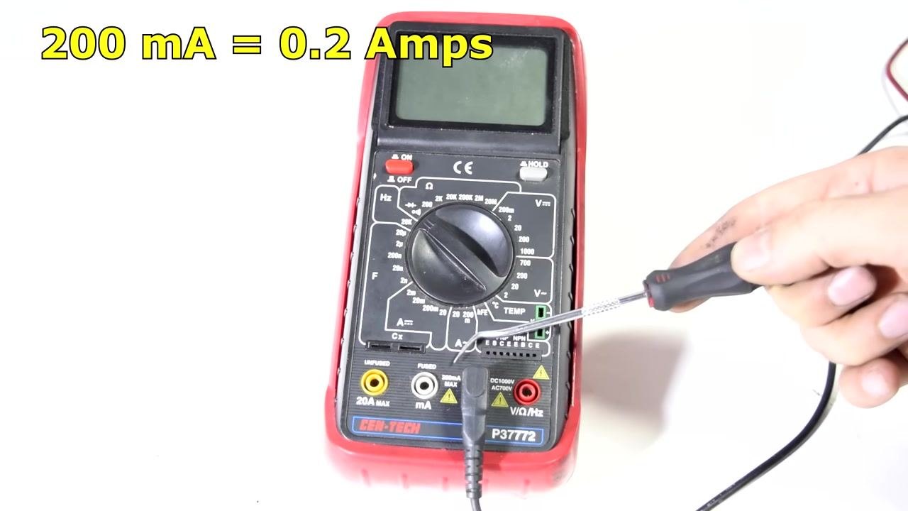
- Use the black mA port for lower current, up to 200 mA, fused.
- Keep the black lead in the COM port.
-
Understand current measurement limits
- The mA port is fused and can measure up to 200 mA (0.2 amps).
- The 20A port is unfused and can measure up to 20 amps.
- If unsure of the expected current, start with the higher current port, then move to the lower port for more precise readings.
-
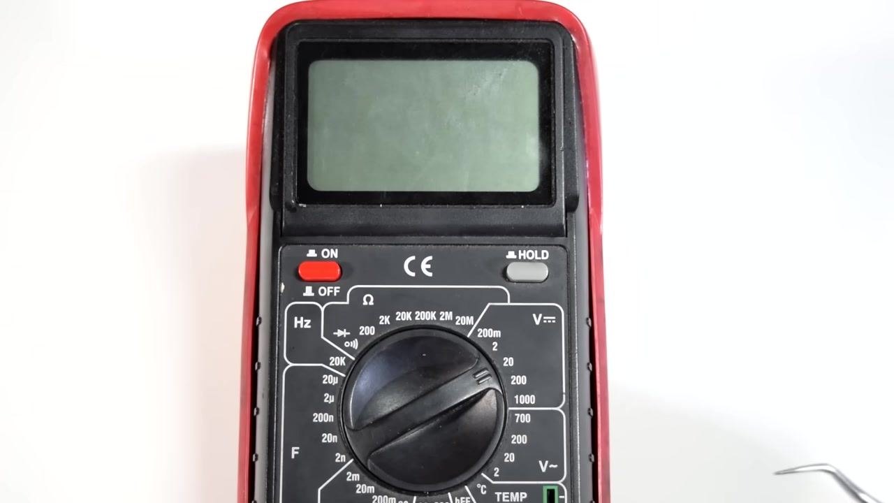
Select the appropriate current range
- Use the rotary dial to select the correct current range (A~ or mA~) based on the expected measurement.
- If unsure, start with the highest range and decrease for more accuracy.
-
Example: Measure the current draw of a light bulb
- Set up the multimeter in series with the circuit containing the light bulb.
- Confirm the test leads are in the correct ports for current measurement.
- Observe the reading to determine the amperage the light bulb uses.
Part 7: Measuring high current (up to 20 amps)
-
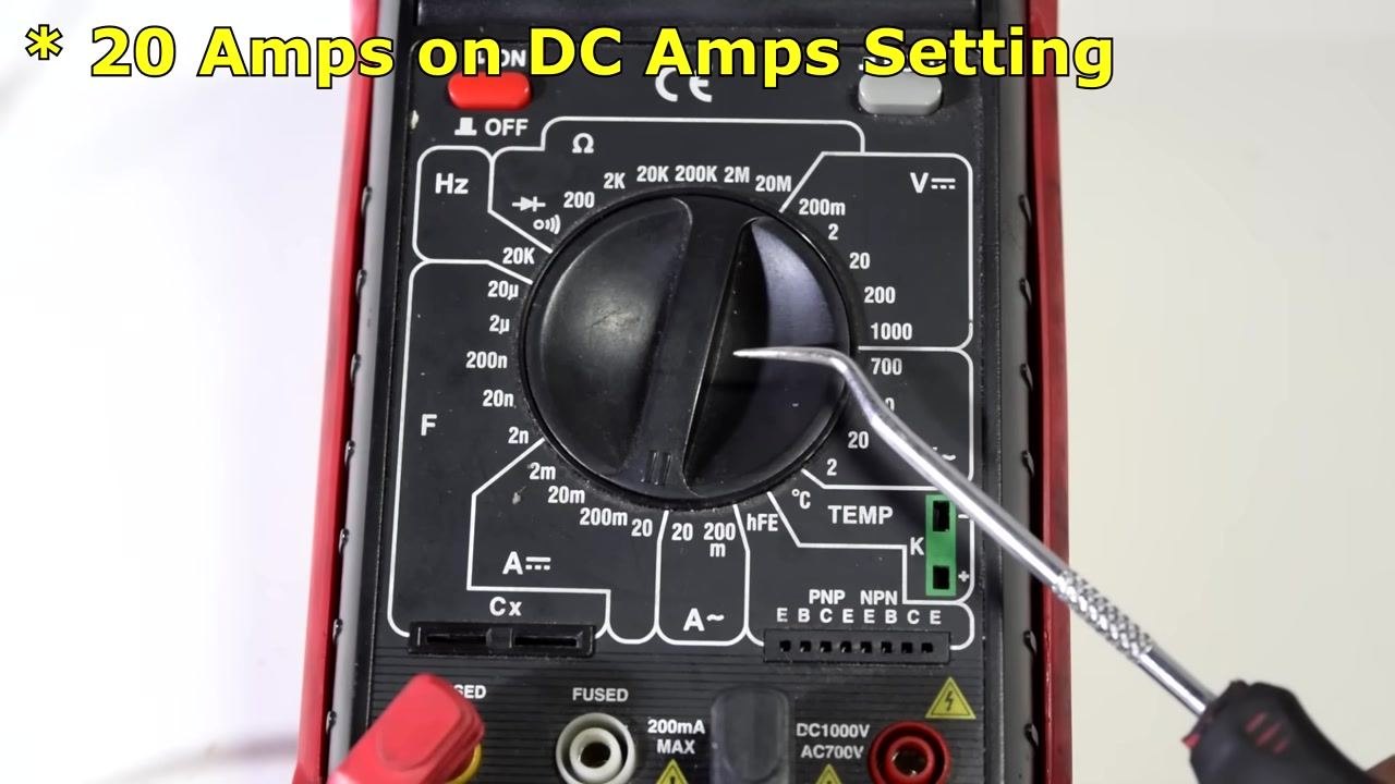
Set the multimeter to the 20A DC amps setting
- Rotate the central dial to the "20A" position in the DC Amps (A⎓) section.
- Use a screwdriver or similar tool if needed for precise adjustment.
- Confirm the dial is pointing exactly to "20" under the "A⎓" marking.
- Note the on-screen reminder: "*20 Amps on DC Amps Setting".
-
Identify the positive battery wire
- Locate the wire connected to the positive terminal of the battery.
- Ensure the wire is accessible and ready for connection to the circuit.
-
Connect the multimeter in series with the circuit
- Attach the black test lead to the positive side of the device or circuit being measured.
- Connect the other test lead to the remaining wire or terminal to complete the circuit.
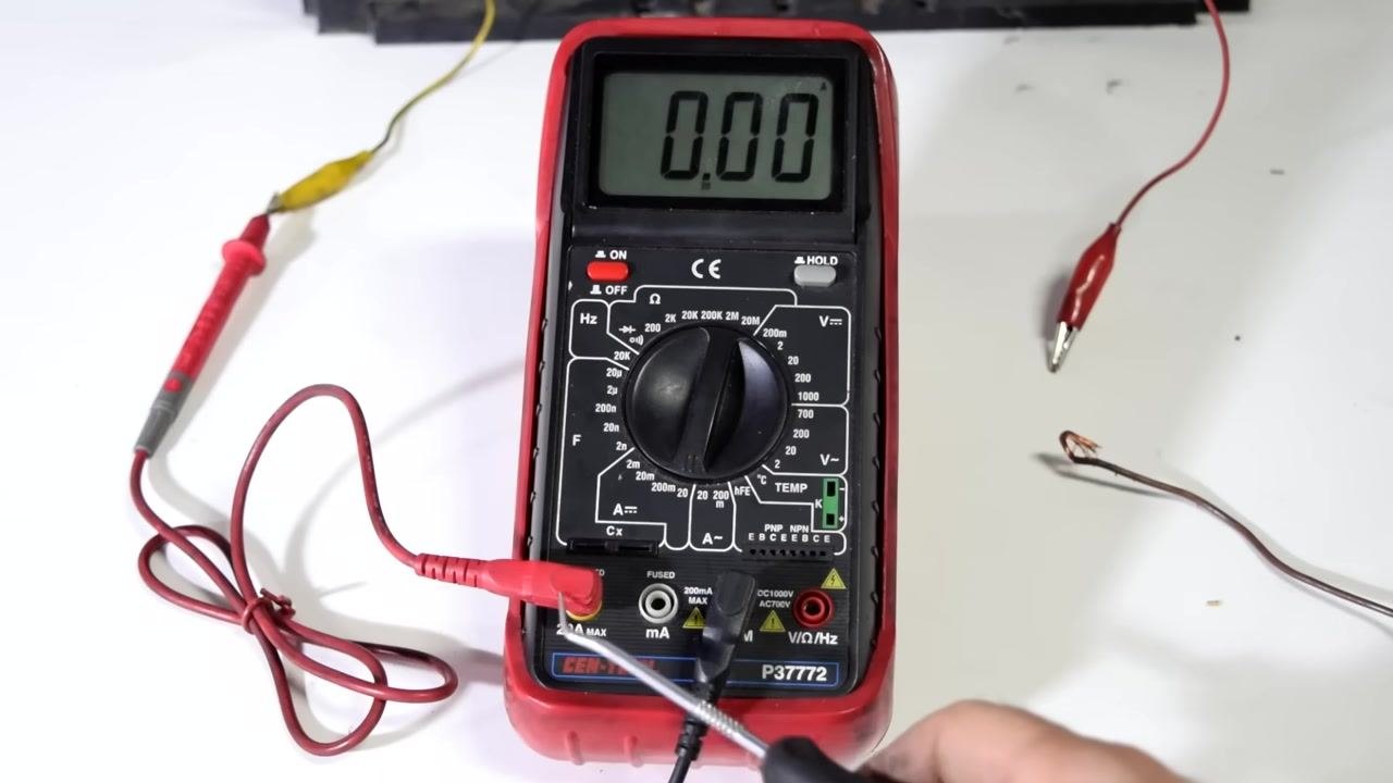
- Confirm all connections are secure and the multimeter display reads "0.00" before powering the circuit.
- Verify test lead placement for high current measurement
- Confirm the red test lead is inserted into the 20A MAX port.
- Confirm the black test lead is in the COM port.
- Use a screwdriver or pointer to double-check the correct port placement.
Safety Note: This setup is required to safely measure up to 20 amps. Using the wrong port may blow the fuse. Always use the 20A port for high current measurements to avoid blowing the internal fuse. The mA port is only rated for currents up to 200 mA and is fused for protection; using it for high current risks damaging the multimeter.
Additional resources
For more advanced diagnostic procedures, refer to the following related video guides:
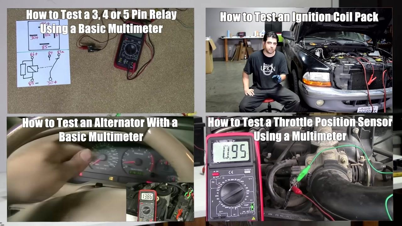
- How to Test a 3, 4, or 5 Pin Relay Using a Basic Multimeter
- How to Test an Ignition Coil Pack
- How to Test an Alternator With a Basic Multimeter
- How to Test a Throttle Position Sensor Using a Multimeter
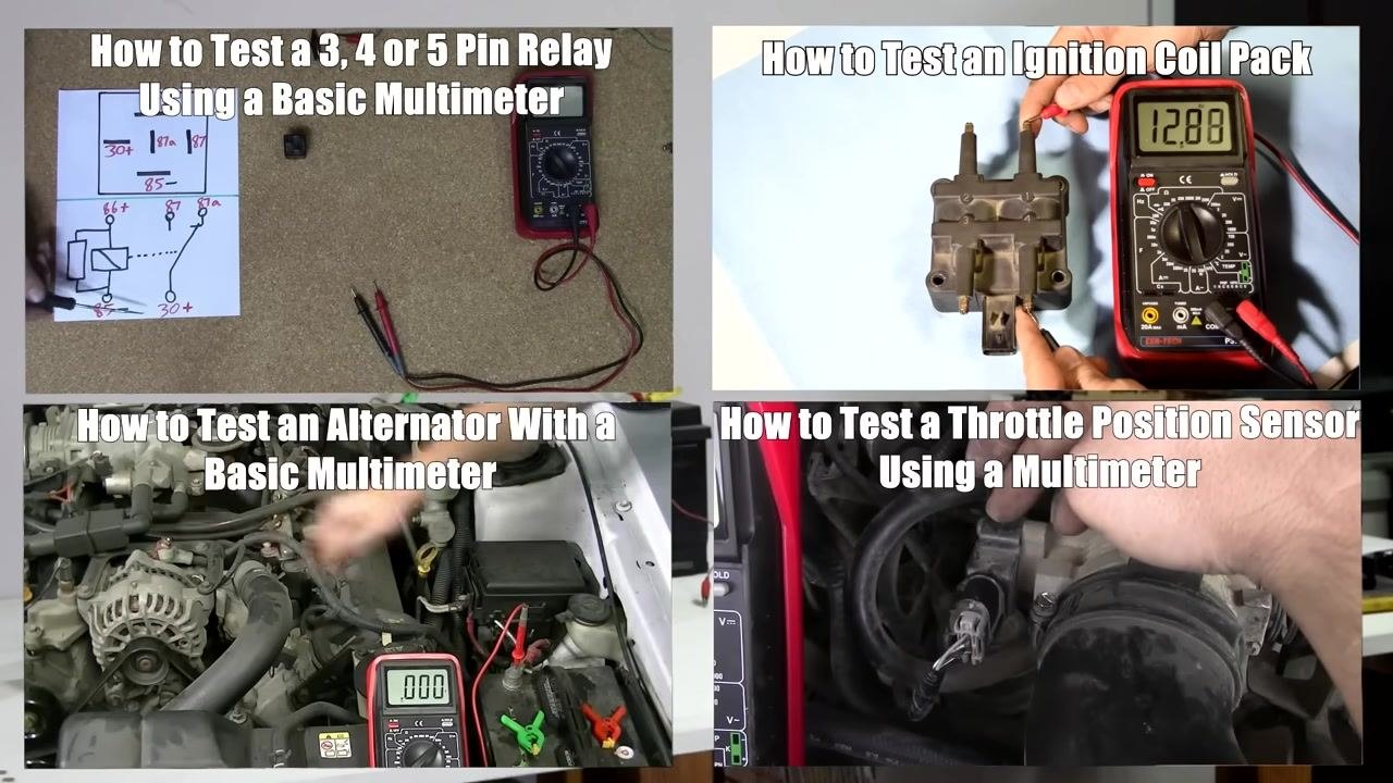
These resources are typically presented as video links or thumbnails for easy access.
Each video guide provides step-by-step instructions and visual demonstrations for specific automotive electrical tests, including wiring diagrams, multimeter readings, and hands-on testing in real-world scenarios.
These demonstrations show multimeter use on actual vehicles, including dashboard readings and sensor testing, with attention to display values and proper probe placement for each test.
Verification and summary
By following this procedure, you can:
- Accurately measure DC voltage from batteries and battery-powered devices.
- Safely measure AC voltage at wall outlets, including verifying case ground connections.
- Measure resistance in components such as spark plug wires and interpret results against expected specifications.
- Test continuity in wires, connectors, and circuits to identify faults or breaks.
- Measure current draw up to 200 mA or up to 20 amps, using the correct ports for each range.
Always confirm that the dial and test lead ports are set correctly before each measurement, and follow the safety notes for AC voltage and current measurement to protect both yourself and your equipment.
What's next
For further diagnostic work, consult the additional video guides referenced above to test relays, ignition coil packs, alternators, and throttle position sensors using the same multimeter techniques described in this procedure.
Generation details: cost, quality tiers
Docsie billed 4,500 credits ($3.15) to analyze this 9-minute video at standard quality. The rewrite, template fill and Word/PDF exports were included. The same video at each quality tier:
| Quality | Frames sampled | Credits | Approx. cost |
|---|---|---|---|
| Draft | every 16-30 s | 2,250 | $1.57 |
| Standard (this guide) | every 8-15 s | 4,500 | $3.15 |
| Detailed | every 4-7 s | 9,000 | $6.30 |
| Ultra | every 1-3 s | 18,000 | $12.60 |
Credits priced at $0.70 per 1,000; plans include a monthly allowance. Enterprise customers on on-premise or bring-your-own-model deployments run this on their own inference and pay no per-video credits.
Generated by Docsie Video-to-Docs on 2026-09-08 from a 8-minute video. Screenshots are frames from the source video and belong to their creator, Ratchets And Wrenches, whose original is embedded above. If you own this video and want the guide removed or credited differently, contact us and we will act within one business day.