
How to Check Continuity With a Multimeter
This standard operating procedure explains how to check continuity with a multimeter, from preparing the device to verifying the results on real components such as a car fuse. Follow each step in order to confirm your multimeter is functioning correctly before you test any wire, fuse, or component.
Video: How To Test For Continuity With A Multimeter-Step By Step Tutorial by Helpful DIY (2016). All credit for the demonstration goes to the creator; watch the original on YouTube. The written guide below was generated from this video by Docsie. Creator? Request a change or removal.
This standard operating procedure explains how to check continuity with a multimeter, from preparing the device to verifying the results on real components such as a car fuse. Follow each step in order to confirm your multimeter is functioning correctly before you test any wire, fuse, or component.
Purpose
The purpose of this procedure is to provide a reliable, repeatable method for testing continuity with a digital multimeter. It covers setting up the device, verifying the continuity function, and applying the test to real-world components.
Scope
This procedure applies to anyone who needs to check continuity with a multimeter, including testing fuses, wires, and other electrical components. It does not cover testing live or powered circuits.
Required equipment
- A digital multimeter with red and black test leads
- The component, wire, or fuse you want to test
- A stable, clean surface to work on
Procedure
Prepare the multimeter
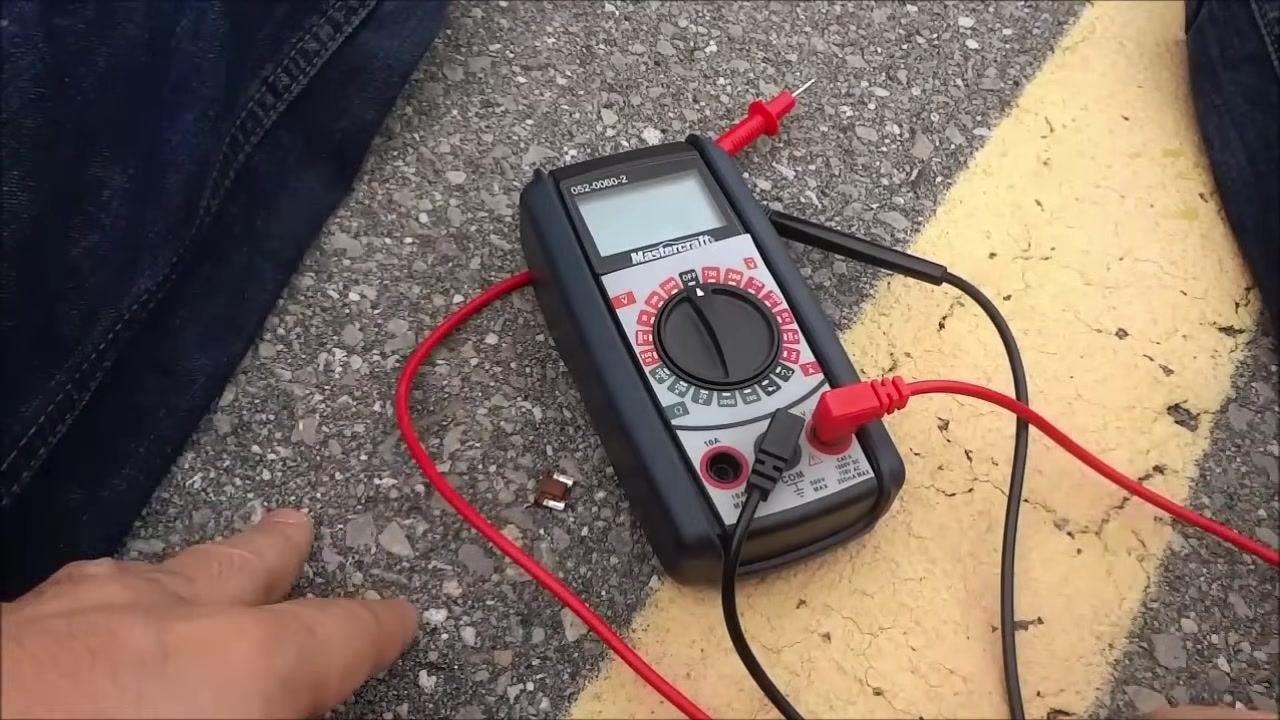
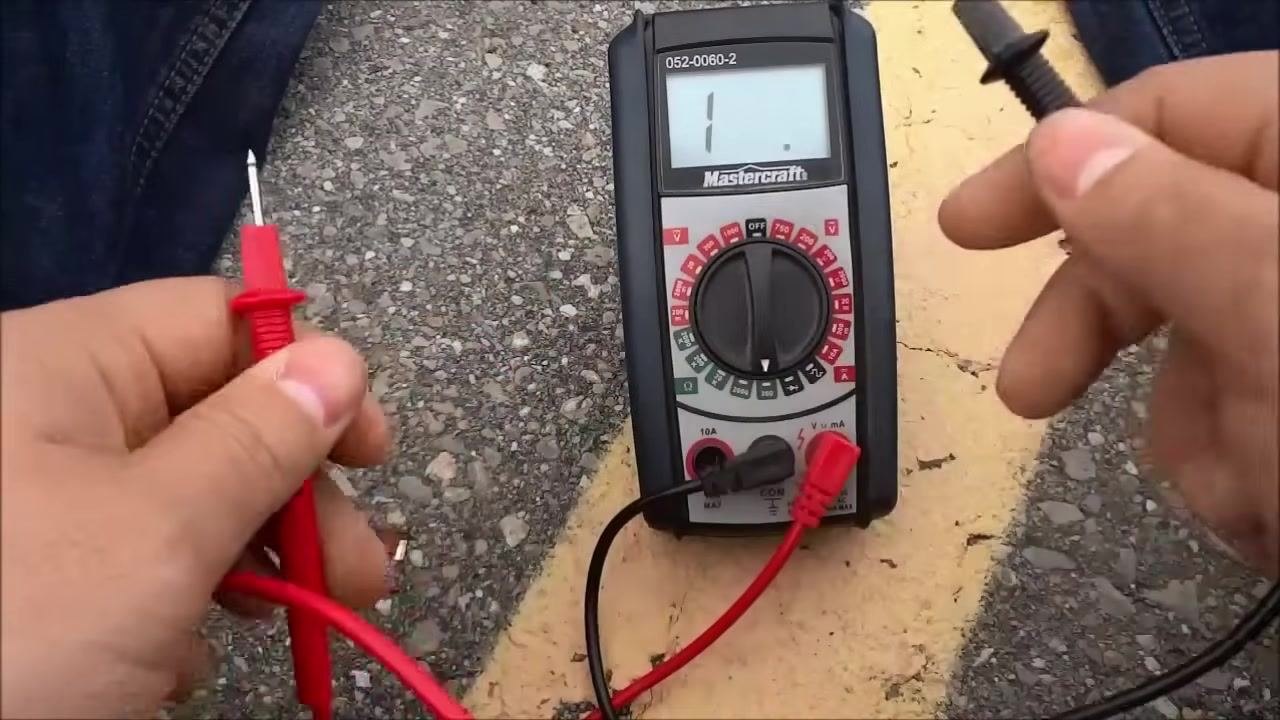
Place the multimeter on a stable surface. Confirm that both test leads are securely connected to the correct ports: the red lead in the port labeled VΩmA and the black lead in the port labeled COM. Power on the multimeter before proceeding.
Set the multimeter to continuity mode
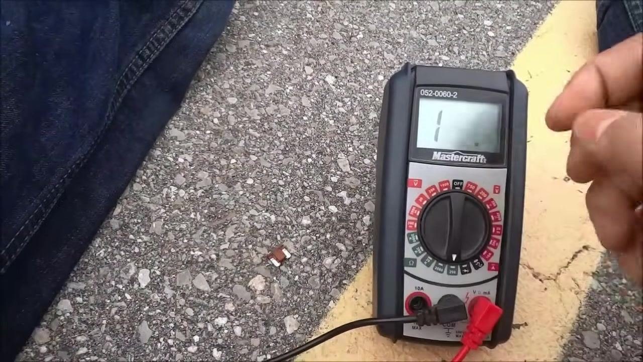
Turn the central dial to the continuity setting, typically marked with the ohms (Ω) symbol. On this model, the setting sits in the green section of the dial. Rotate the dial until the pointer aligns with the Ω symbol.
Organize the test leads
Arrange the test leads so they are untangled and easy to handle, and confirm they remain fully inserted into their respective ports.
Verify the multimeter shows no continuity
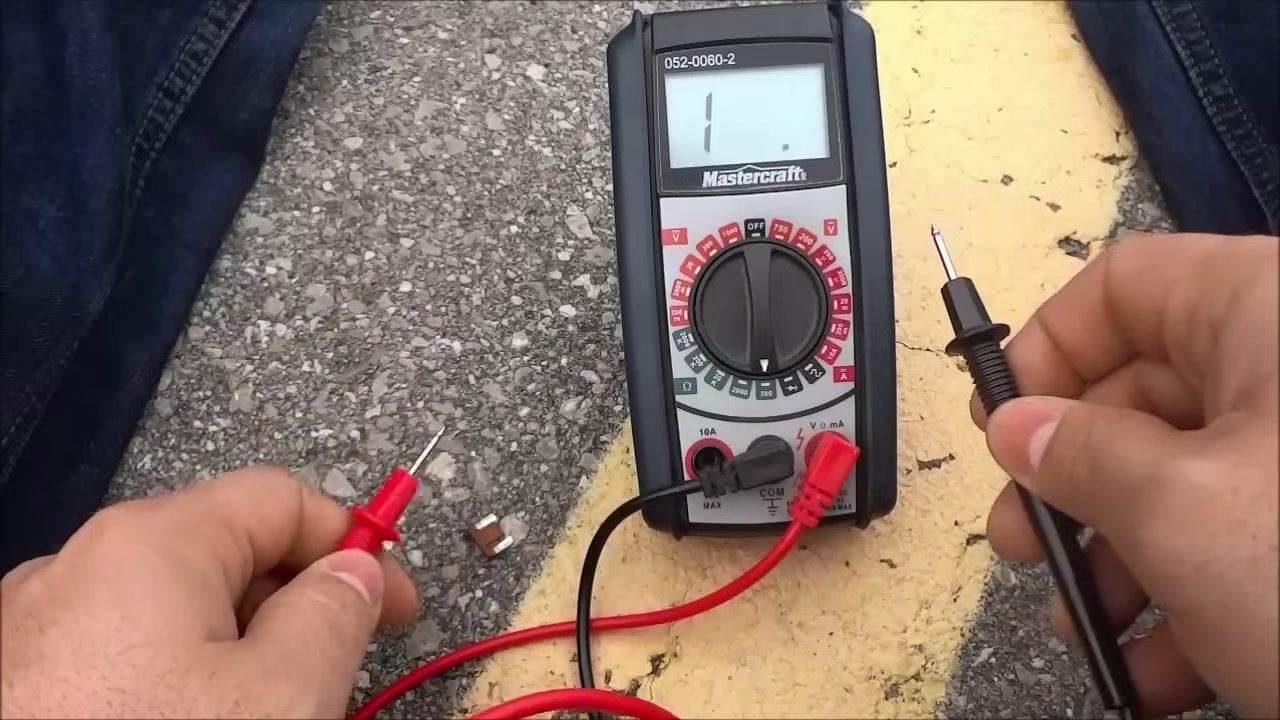
Hold the two test lead tips apart and check the display. It should show a high resistance reading or "1", confirming there is no continuity when the leads are not touching.
Touch the test leads together
Briefly touch the metal tips of the red and black test leads together and observe the display. A reading of "0", or a value very close to zero (such as 0.5 or 0.6), confirms good contact and continuity. A slightly non-zero reading may indicate a low battery or dirty terminals, but it still confirms continuity.
Interpret the self-test results
If the display shows "0" or a value close to zero, the multimeter is working correctly for continuity testing. If the display stays at "1" or a high value, check the battery and clean the test lead tips before continuing.
Position the leads on your target component
Take the component or wire you want to test. Hold one test lead at one end of the component and the other test lead at the opposite end.
Test a car fuse for continuity
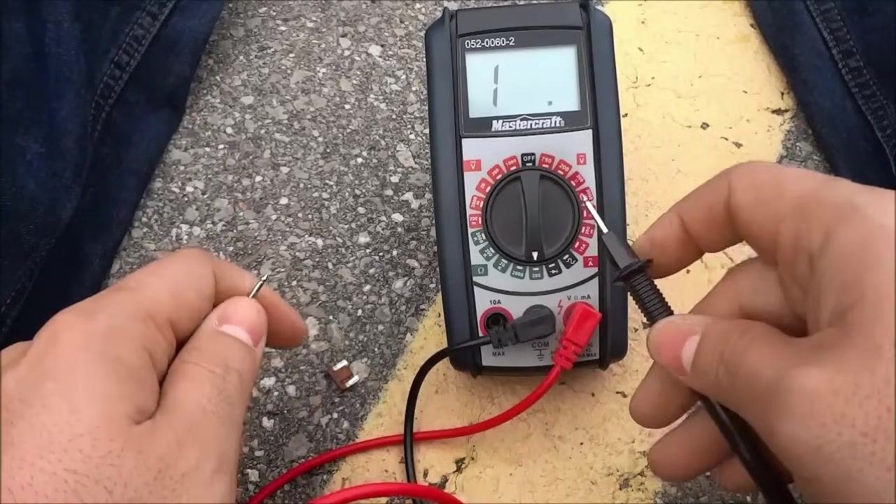
Hold the car fuse securely in one hand. Touch one test lead to one end of the fuse and the other test lead to the opposite end. A reading of "0" or close to it (such as 0.5 or 0.6) confirms the fuse has continuity. If the display stays at "1" or a high value, the fuse does not have continuity and may be faulty.
Interpret the continuity test results
A reading close to zero (e.g., 0.6 or 0.5) means the fuse is good and has continuity. A reading that stays at "1" means the fuse is blown or the circuit is open.
Apply the same method to other components
Use this method to check continuity on a wide range of wires, fuses, and other objects. Always confirm both test leads are making solid contact with the component being tested.
Follow safety precautions
Only test components that are safe and disconnected from any live circuit. Avoid testing high-voltage or powered circuits, as this can damage the multimeter or cause personal injury.
Conclude the test
Once testing is complete, turn off the multimeter, disconnect the test leads, and store the multimeter and its accessories safely.
Verification and summary
By following this procedure, you can reliably check continuity with a multimeter on fuses, wires, and other components. Confirm the self-test in Steps 4–6 before testing any component, and always ensure the test leads are clean and the multimeter is set to the correct mode for accurate results.
What's next
Apply this same continuity-checking procedure whenever you need to verify whether a fuse, wire, or component is intact. Always prioritize safety by testing only components that are disconnected from live circuits.
Generation details: cost, quality tiers
Docsie billed 1,500 credits ($1.05) to analyze this 3-minute video at standard quality. The rewrite, template fill and Word/PDF exports were included. The same video at each quality tier:
| Quality | Frames sampled | Credits | Approx. cost |
|---|---|---|---|
| Draft | every 16-30 s | 750 | $0.52 |
| Standard (this guide) | every 8-15 s | 1,500 | $1.05 |
| Detailed | every 4-7 s | 3,000 | $2.10 |
| Ultra | every 1-3 s | 6,000 | $4.20 |
Credits priced at $0.70 per 1,000; plans include a monthly allowance. Enterprise customers on on-premise or bring-your-own-model deployments run this on their own inference and pay no per-video credits.
Generated by Docsie Video-to-Docs on 2026-09-08 from a 2-minute video. Screenshots are frames from the source video and belong to their creator, Helpful DIY, whose original is embedded above. If you own this video and want the guide removed or credited differently, contact us and we will act within one business day.