
How to Use Power Copy in CATIA
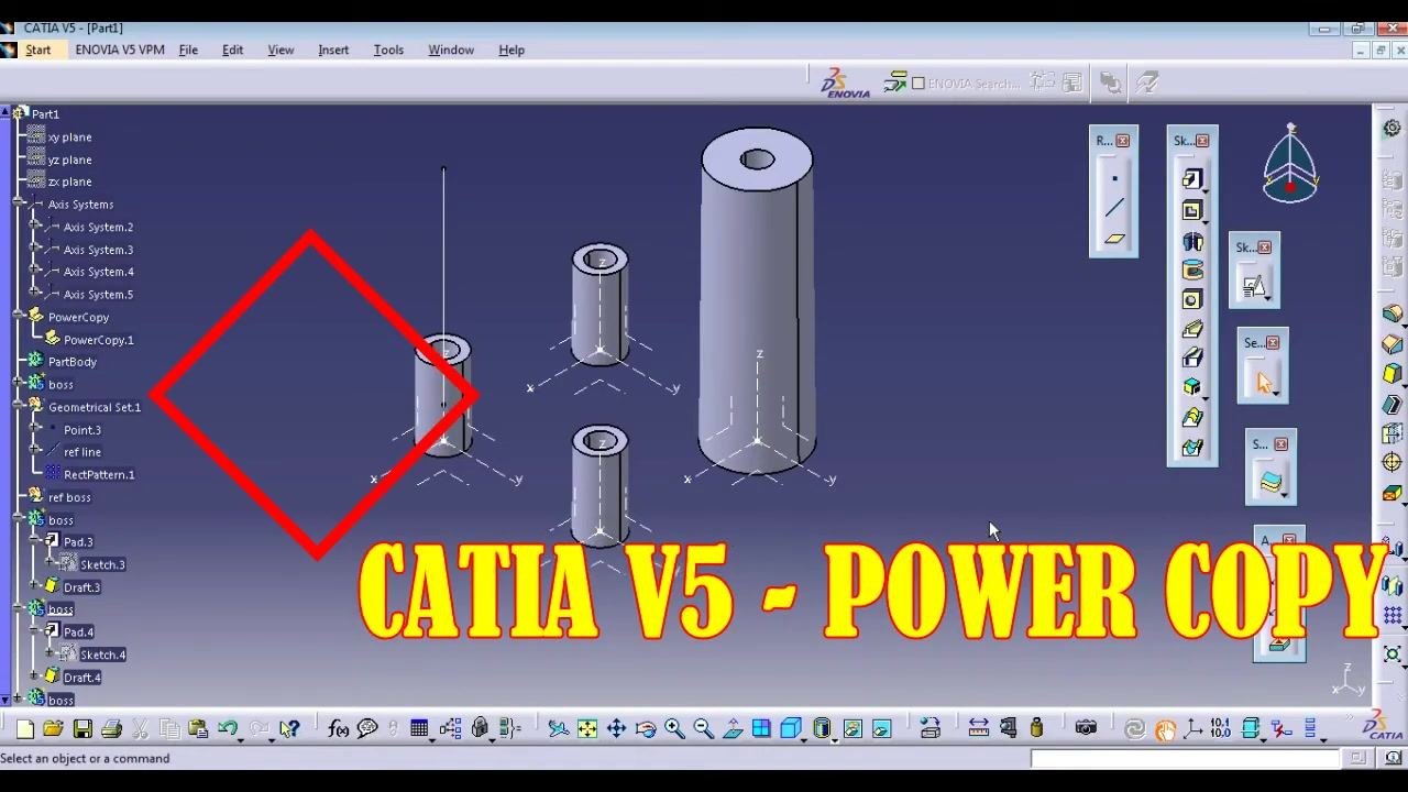
Power Copy is a reusable feature in CATIA V5 that lets you capture a piece of geometry, such as a boss with draft, and instantiate it elsewhere in your model using reference points and lines as inputs. This guide walks through how to use Power Copy in CATIA V5, from setting up reference geometry to creating, instantiating, and editing the Power Copy feature.
Video: CATIA V5-POWER COPY by CAD DESIGN (2018). All credit for the demonstration goes to the creator; watch the original on YouTube. The written guide below was generated from this video by Docsie. Creator? Request a change or removal.
Power Copy is a reusable feature in CATIA V5 that lets you capture a piece of geometry, such as a boss with draft, and instantiate it elsewhere in your model using reference points and lines as inputs. This guide walks through how to use Power Copy in CATIA V5, from setting up reference geometry to creating, instantiating, and editing the Power Copy feature.
Prerequisites
- CATIA V5 installed and ready to launch.
- A basic understanding of sketching, pads, and drafts in CATIA V5.
Start CATIA V5 and open a new part file
Launch CATIA V5 and open a new part file to begin modeling. The workspace displays the default planes (xy, yz, zx) and an empty tree structure.
Create a reference point
In the tree, go to Geometrical Set and insert a new point (for example, Point.3) into the workspace.
Create a reference line
With the point selected, open the Line Definition dialog box. Set Line type to Point-Direction, choose the point you created (for example, Point.3) as the Point, and select a Direction (for example, the Z Component).
Set Start to 4mm and End to 30mm, then click OK to create the reference line.
Insert an axis system
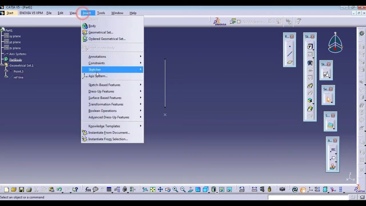
Go to Insert in the top menu, then select Axis System.... Insert a new axis system at the origin or as required by your design.
Insert a new body
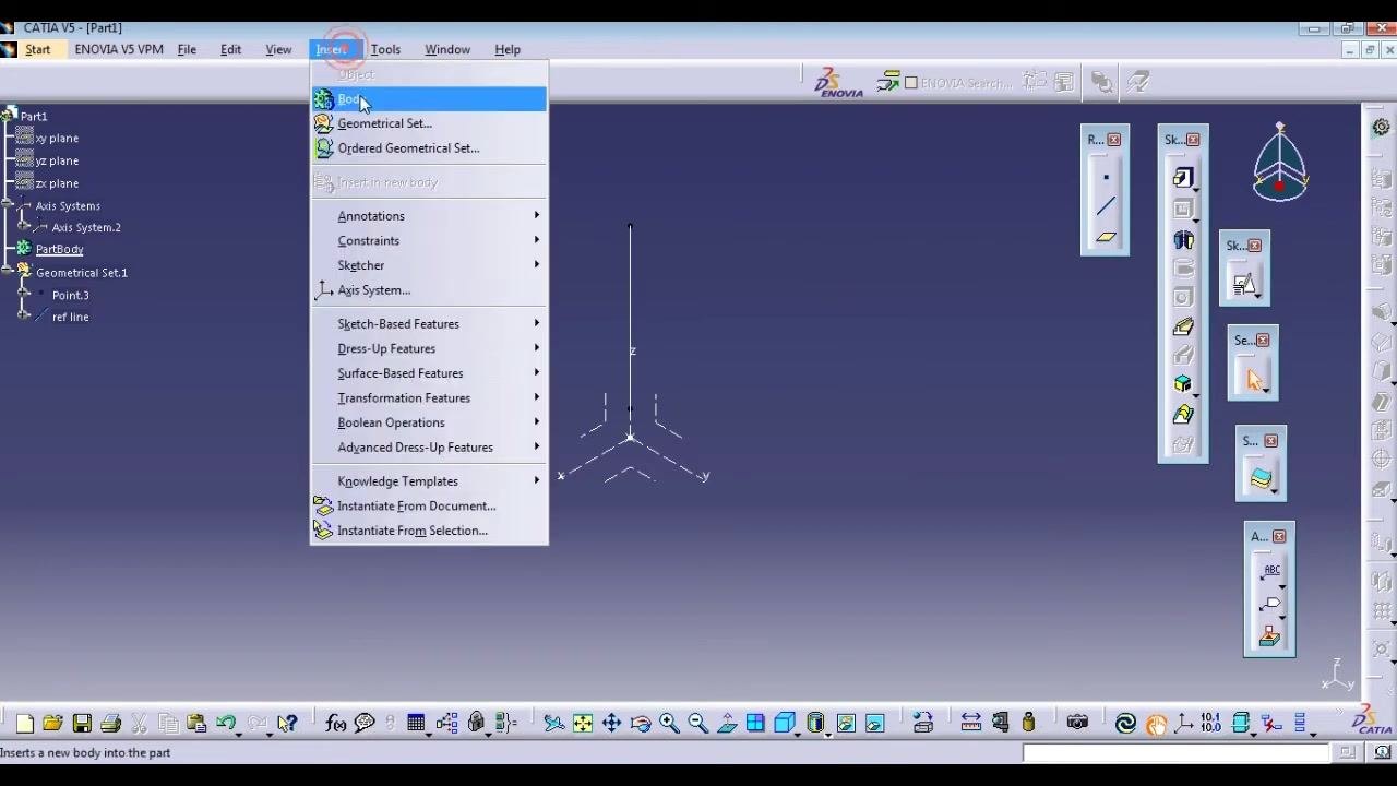
Go to Insert again and select Body to add a new body to the part. Give it a descriptive name (for example, "creative pose").
Open the subtree of the new body
Right-click the new body in the tree and select Open Sub-Tree to expand it and work within this body.
Create a sketch on the reference line
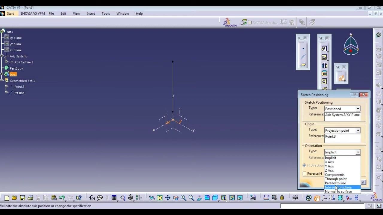
With the new body active, create a new sketch. In the Sketch Positioning dialog box, set Type to Positioned, Reference to the appropriate plane (for example, Axis System.2/XY Plane), Origin to Projection point referencing your point (for example, Point.3), and Orientation to Parallel to line referencing the line you created.
Draw and dimension a circle
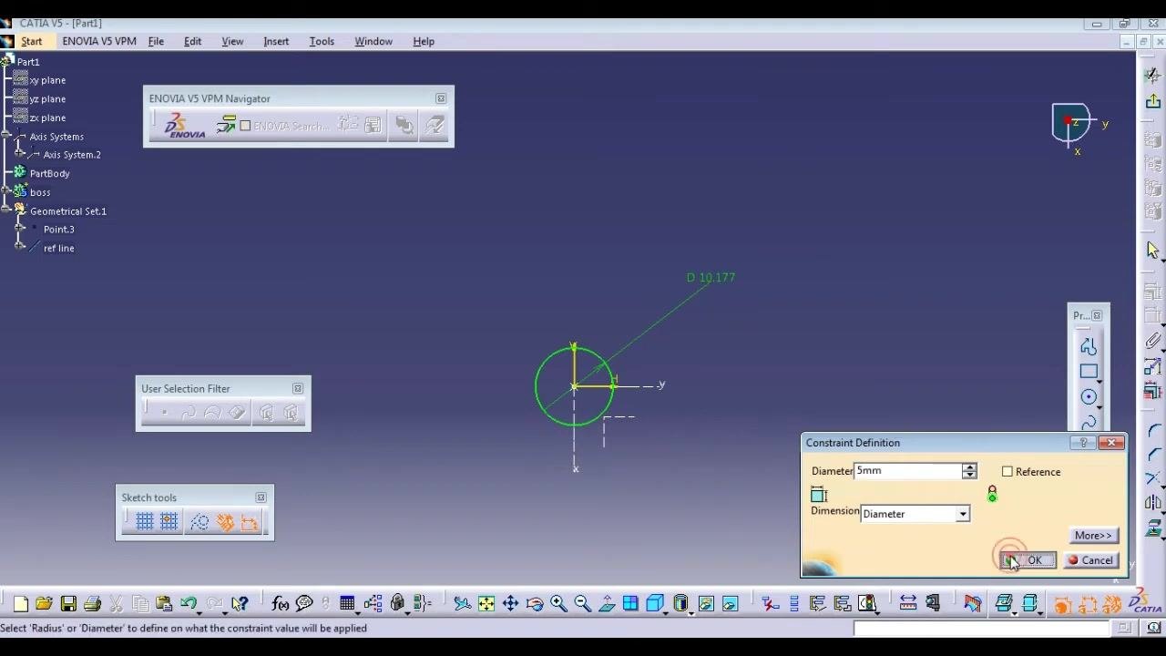
In the sketch, draw a circle centered at the projection point. Open the Constraint Definition dialog box, set the diameter to 5mm, and click OK to apply the dimension.
Cut the sketch if required
Use the appropriate tool to cut or trim the sketch as needed for your design.
Create the next circle
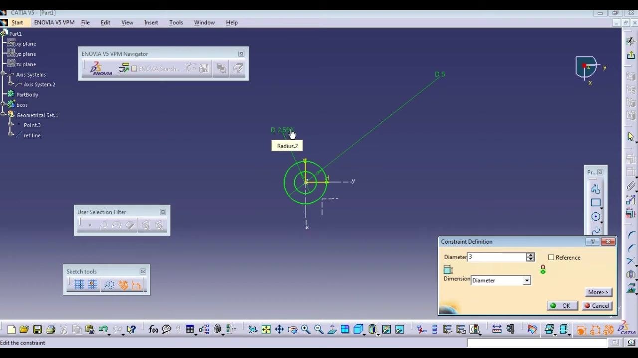
Enter the sketching environment on the appropriate plane and use the circle tool to draw a new circle centered at the origin or projection point. The circle should be concentric with the previous geometry.
Add a diameter constraint
Open the Constraint Definition dialog box, set the diameter of the new circle to 3mm, and click OK to confirm.
Create a boss using the reference line and point
Use the boss feature to create a solid based on the reference line and the point, ensuring it is properly aligned with the reference geometry.
Apply draft to the boss faces
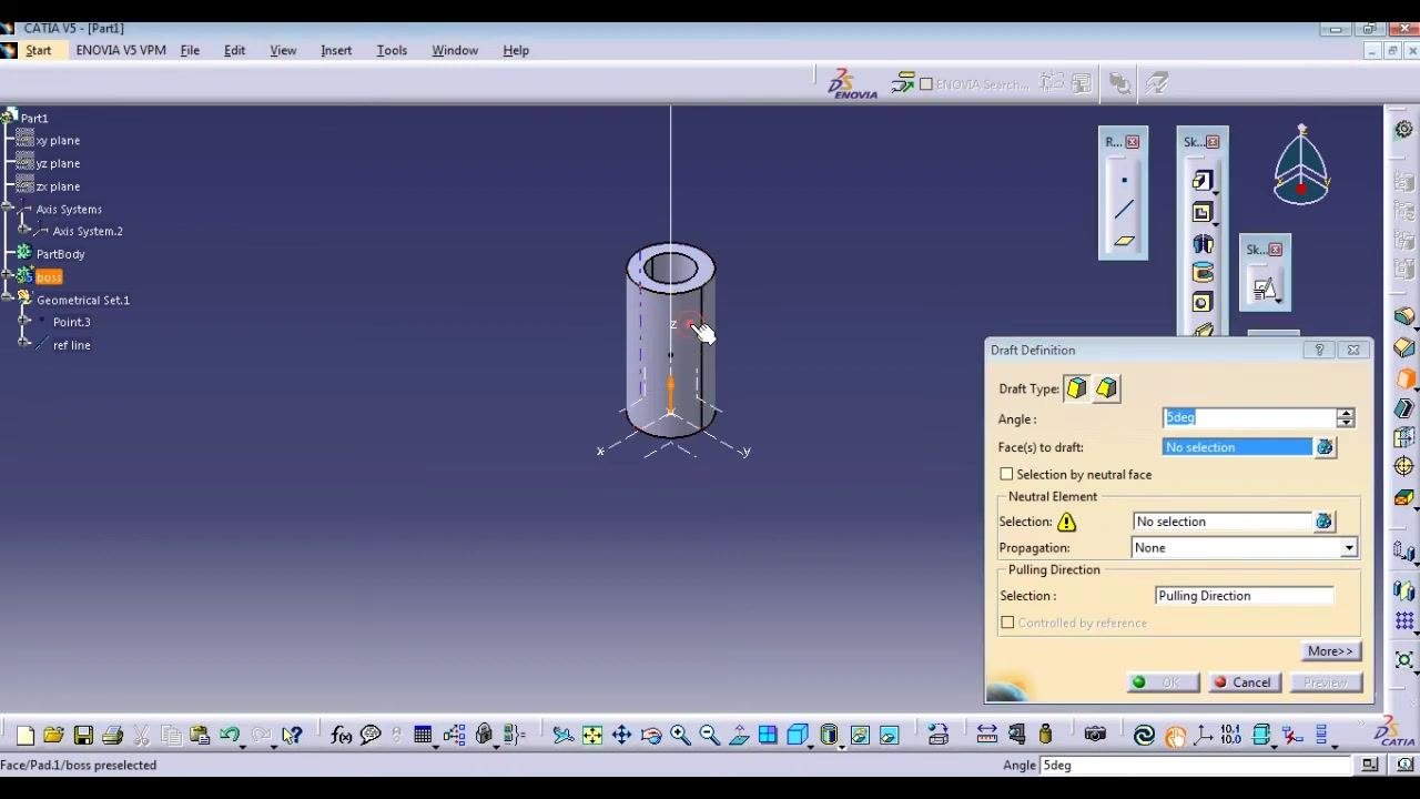
Exit the sketch, return to the 3D workspace, and select the cylindrical boss feature. Open the Draft Definition dialog box and select the two faces of the boss that require drafting.
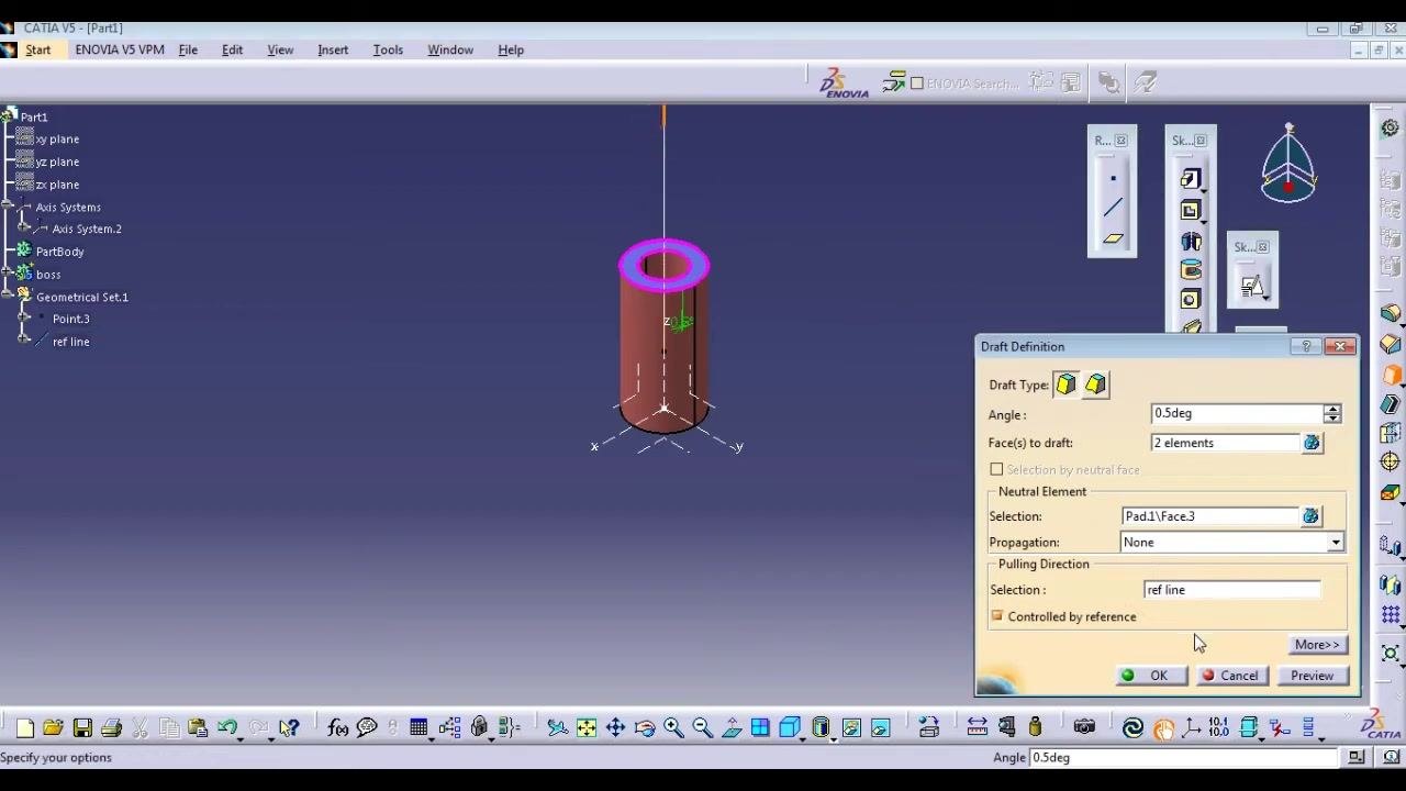
In the Draft Definition dialog box, set the draft angle to 0.5 degrees and confirm that both required faces are selected.
In the same dialog box, set Pulling Direction to the reference line you created earlier (for example, ref line), then click OK to apply the draft.
Initiate Power Copy creation
Go to Insert, navigate to Knowledge Templates, and select Power Copy....
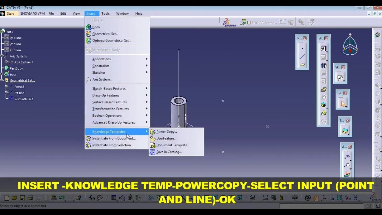
Define Power Copy inputs
In the Powercopy Definition dialog box, select the boss as the main feature. Under Inputs of components, select only the point (for example, Point.3) and the reference line (for example, ref line) as the Power Copy inputs, then name the Power Copy appropriately (for example, "PowerCopy").
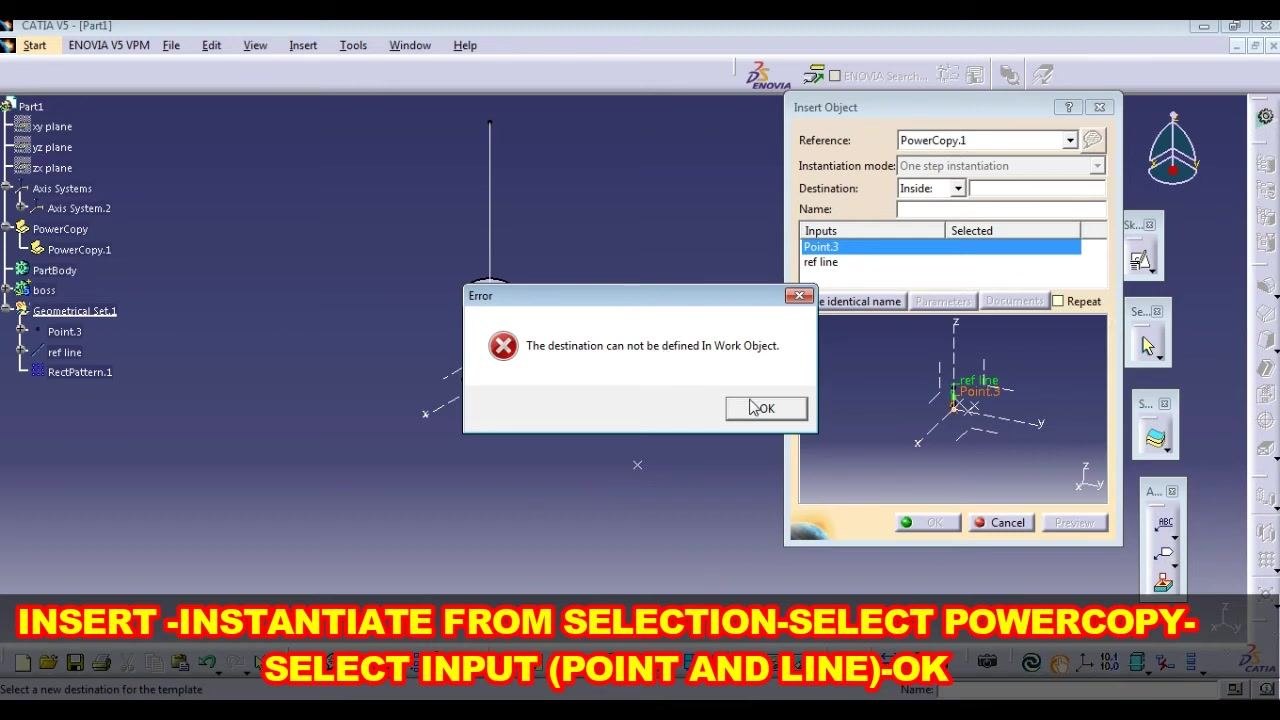
Attempt to instantiate the Power Copy
Open the Insert Object dialog box and select PowerCopy.1 as the reference. Set the instantiation mode to One step instantiation and attempt to set the destination as Geometrical Set.1, selecting Point.3 and ref line as the required inputs.
If you see an error stating "The destination cannot be defined in Work Object," click OK to close the error dialog box.
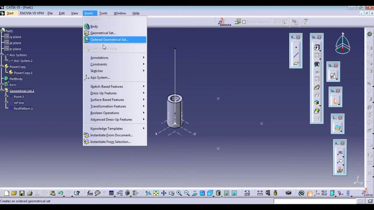
Create a new geometrical set for reference
Cancel the current instantiation. Go to Insert and select Geometrical Set... to create a new geometrical set. Name it ref boss (or another appropriate name) and confirm creation.
Instantiate the Power Copy into the new geometrical set
Go to Insert, navigate to Knowledge Templates, and select Instantiate From Selection.... In the Insert Object dialog box, set the destination to the newly created ref boss and select Point.3 and ref line as the required inputs.
In the workspace, select the reference line (for example, ref line) to define the direction, and confirm it is correct and supported for the instantiation. Click OK to instantiate the Power Copy.
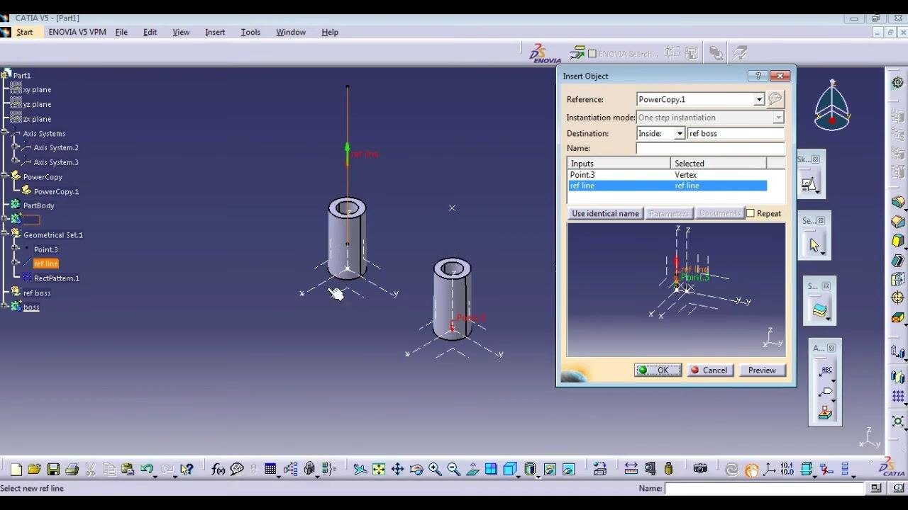
Repeat Power Copy instantiation for additional geometry
If you need to instantiate the Power Copy on another part, go to Insert and select Instantiate From Selection... again. Choose PowerCopy.1 as the reference and set the destination to the appropriate geometrical set or position (for example, After boss). Select the next point and reference line as inputs.
Use the Preview button to check the instantiation, enable the Repeat option if you want to instantiate multiple times, and click OK to confirm or Cancel to abort.
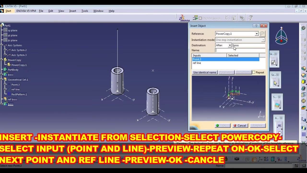
Verify and adjust instantiated features
After instantiating, check the direction and alignment of the new features. Select the correct point and reference line for each instantiation if necessary, and use the Preview function to verify placement before finalizing. Repeat the process for additional points and lines as needed.
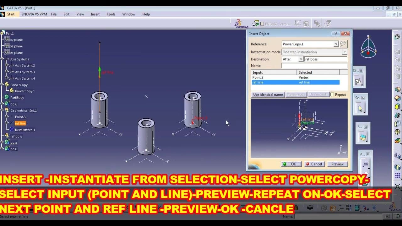
Modify feature parameters, such as height
To change the height or other parameters of a created boss, select the boss feature in the tree (for example, boss under ref boss) and double-click it to open its definition dialog box (for example, Pad Definition). Change the Length value to the desired height (for example, Length = 31mm) and click OK to apply the change.
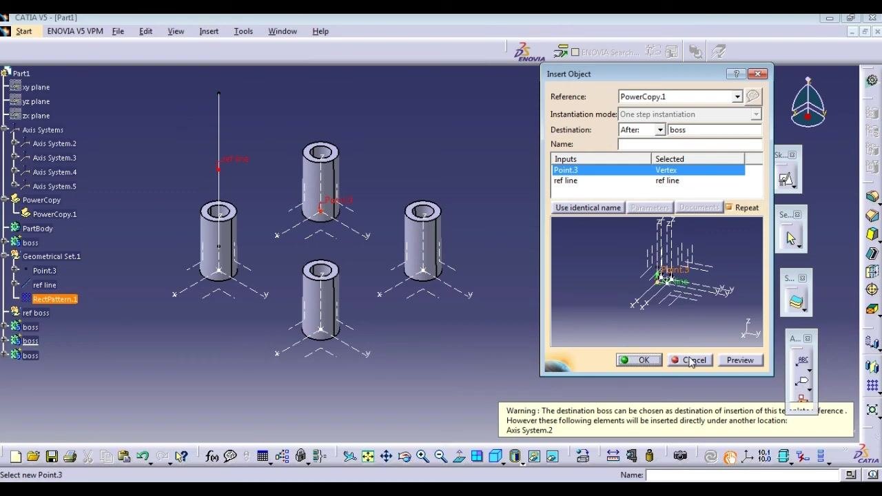
Edit the sketch of a feature
To modify the underlying sketch of a boss, expand the boss feature in the tree to locate its sketch (for example, Sketch.3) and double-click it to open the sketcher workbench. Make the necessary changes to the sketch geometry or constraints, such as changing the diameter by editing the constraint value.
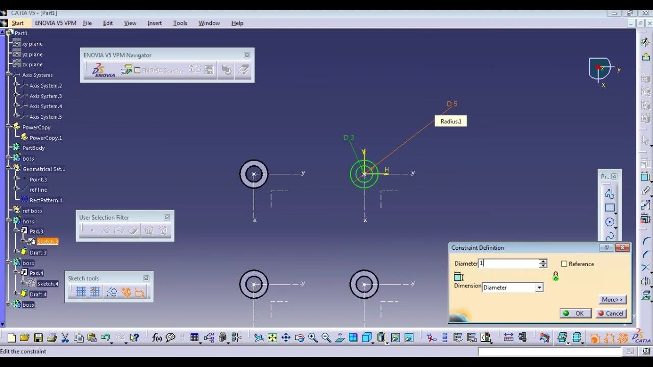
Update feature constraints
In the sketch, select the dimension or constraint you want to modify (for example, Diameter) and enter the new value (for example, changing diameter from 1 to 10). Click OK in the Constraint Definition dialog box to confirm the change.
Perform a local update of the model
After editing the sketch or feature parameters, perform a local update to apply the changes. Right-click the feature or geometrical set and select Local Update, or use the update button in the toolbar. Verify that the changes are reflected in the 3D model and that all dependent features are updated accordingly.
Summary
By following these steps, you have learned how to use Power Copy in CATIA V5 to create foundational reference geometry, define a Power Copy, instantiate it across your model, and edit instantiated features. This workflow keeps your model flexible and fully parametric for future modifications.
Generation details: cost, quality tiers
Docsie billed 3,000 credits ($2.10) to analyze this 6-minute video at standard quality. The rewrite, template fill and Word/PDF exports were included. The same video at each quality tier:
| Quality | Frames sampled | Credits | Approx. cost |
|---|---|---|---|
| Draft | every 16-30 s | 1,500 | $1.05 |
| Standard (this guide) | every 8-15 s | 3,000 | $2.10 |
| Detailed | every 4-7 s | 6,000 | $4.20 |
| Ultra | every 1-3 s | 12,000 | $8.40 |
Credits priced at $0.70 per 1,000; plans include a monthly allowance. Enterprise customers on on-premise or bring-your-own-model deployments run this on their own inference and pay no per-video credits.
Generated by Docsie Video-to-Docs on 2026-10-14 from a 5-minute video. Screenshots are frames from the source video and belong to their creator, CAD DESIGN, whose original is embedded above. If you own this video and want the guide removed or credited differently, contact us and we will act within one business day.